 Ted Yapo
Just a quick update to get me familiar with project logs on hackaday.io, and into the habit of sharing.
Documentation
I added a bunch of PDF documentation to the project today. I had it lying around, and figured between the various documents, you could get a good idea of how this project works:
- DDL Backgrounder : a dryly-worded introduction to early single-stage DDL gates. If you've never seen a provisional patent application before, they might look a little like this years after they've expired. Single-stage DDL gates suffer from poor fan-out, and are difficult to make work in large designs. I don't hold any patents in any country I that know about, for anyone wondering.
- DDL01 Datasheet : When I first thought about building a computer with diodes, I imagined what parameters I'd want to see on a datasheet for the gates. Then I figured I might as well write one. This is DDL 2.0, which works well enough to build large-scale systems. 46 of these boards are used in the Diode Clock.
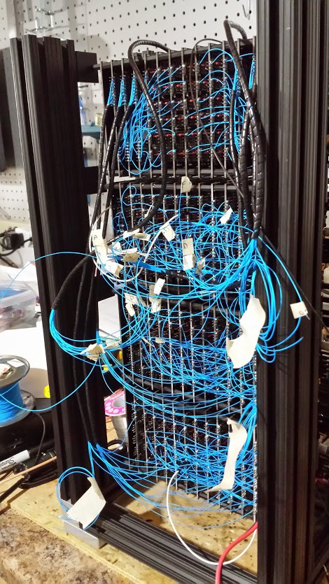
- Minutes / Seconds Counter Wiring : A schematic and wiring diagram for the seconds and minutes counter stacks. Each stack consists of (11) DDL01 boards wired as two decoded Johnson counters, a mod-10 counter for the ones digit and a mod-6 counter for the tens. These probably could have been optimized, but I wanted the logic-level design to be "easy" having spent so much time getting the gates to work. The counters are wired "by hand" with 30ga wire-wrap wire, then soldered for good measure. It was no picnic - see below.
- Hours Counter Wiring : Schematic and wiring diagram for the hours counter stack. Again two decoded Johnson counters (mod-10 and mod-3), but with 24H detection and reset circuitry, which uses a belt-and-suspenders reset latch to ensure both digits are reset to "00" before releasing the reset signal. I was afraid of violating minimum reset pulse times here.
- DDL Demo Board Datasheet : I've tried to come up with the simplest DDL logic circuit that you can't build with "traditional" diode AND or OR gates. This might be it - an RS latch using two 1N4148s, two 1N4007s, and two LEDs. The LEDs are used as part of the RF voltage doubler. The datasheet explains it all.
Wiring the Clock
It wasn't as fun as it looks...well, OK, it was :)
Two Problems
Open Documentation Source
I have two problems at the moment. First, in the spirit of open-source, I am willing to release the source code for the above linked PDF documentation under an open-source license if anyone is interested. It's nightmarish latex and xfig and gnuplot, but hey, some people actually like that kind of drudgery. Let's leave it at that - if anyone wants to create a derived work from that documentation, let me know, and I'll release it. I am going to release the board design files, though, even if nobody asks ;) This brings me to the second problem.
Inductor Sourcing
After I made my first prototype DDL gate, I looked around for suitable inductors, which were shaping up to be the most expensive part of the design. I found a great deal on super-miniature 47uH formed-lead chokes (Taiyo Yuden LAL02VD470K) on ebay, and bought all the seller had, because they were very cheap, and I had dreams of building a full computer with DDL. They were so cheap because they were discontinued: I believe I have world's remaining supply - five boxes of 2,000, minus the 500 or so I've used.
So, here's the problem. Nobody seems to make through-hole inductors in this size any more, so if you use the PCB designs as-is, you can't buy inductors that fit easily. If anyone wants to build DDL boards, I think there are three options:
- Re-design the boards to accept larger through-hole (or SMD) inductors which are readily available. The boards are tight, but it might be possible.
- Use the existing PCB design with larger inductors mounted vertically on the boards. Clearance to next boards in a "stack" might be an issue.
- Ask me for some of my inductor stash, and we'll work something out
In any case, I'll be working on releasing the design files in the next week or so.
Next Steps
I'll be releasing the design files for the various boards, including:
- Eagle PCB Design Files: I already have gerbers up on OSH Park for most of them (not currently shared), but I'll be putting Eagle files up there and here on hackaday.io, too. I used OSH Park for the many generations of prototypes, but for the Diode Clock, the boards absolutely. had. to. be. black.
- LTC Spice simulation files: Yes, you can simulate DDL gates with Spice. The trick is having a good model for the 1N4007.
The plan is to document and release things in roughly this order:
- DDL Demo Board
- DDL01 Hex NOR
- DDL03 Hexadecimal to 7-Segment ROM
- Simple DDL circuits to experiment with
- DDL02 "Chainsaw" Power Supply
- DDL04 "Whisper" Spread Spectrum Exciter
- TCXO Timebase and diode-only oscillator timebase experiments
Zed Naught Laboratories
If you look closely at some of the design files, you'll see my company, Zed Naught Laboratories, LLC, and the alternate domain z0labs.com. Don't worry, I'm not trying to sell you anything. It's not that kind of company.
Discussions
Become a Hackaday.io Member
Create an account to leave a comment. Already have an account? Log In.