0%
0%
Call Button
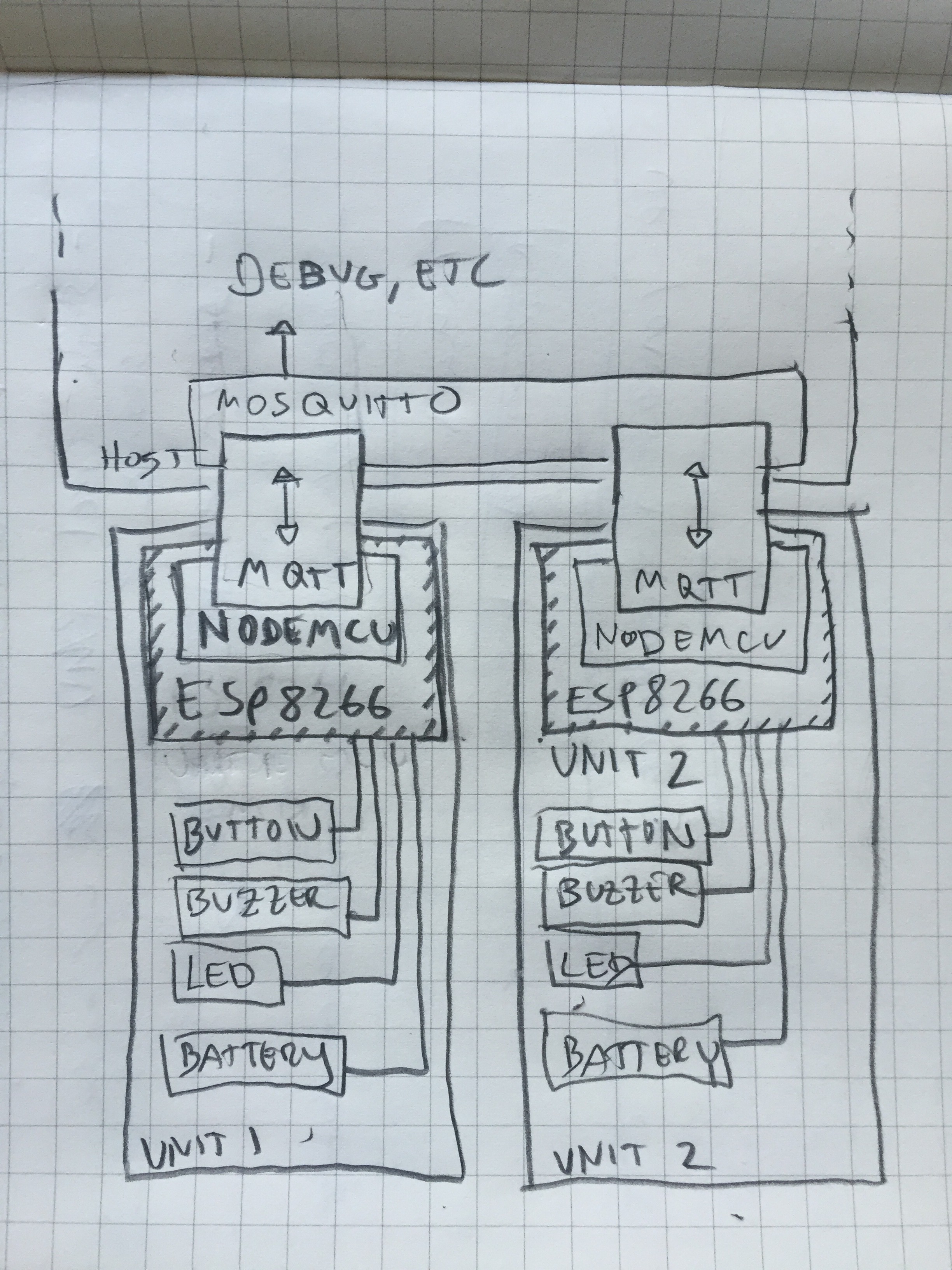
Minimal two-way wireless communication
Become a Hackaday.io member
Already have an account? Log in.
Just one more thing
To make the experience fit your profile, pick a username and tell us what interests you.
Pick an awesome username
hackaday.io/
Your profile's URL: hackaday.io/username. Max 25 alphanumeric characters.
Pick a few interests
Projects that share your interests
People that share your interests


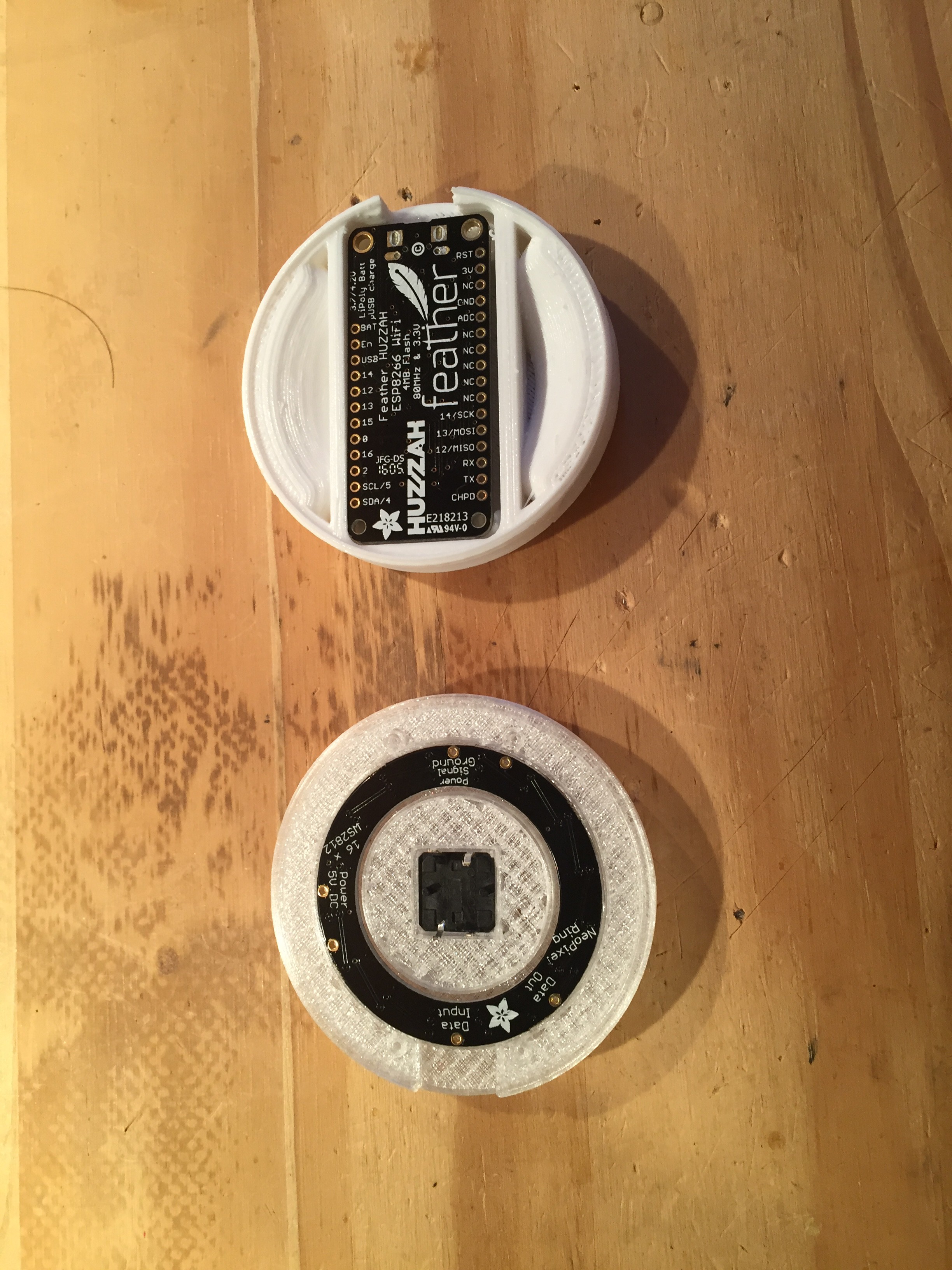
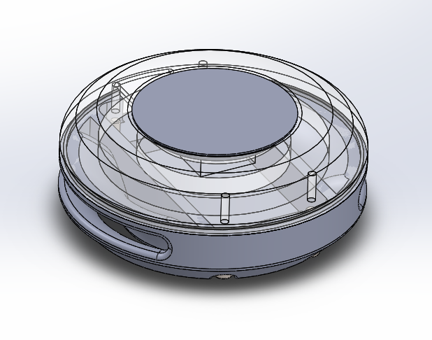
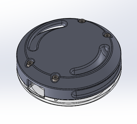 After a test fitting an initial print, these CAD files will be going into the repository. Between this and the Adafruit BOM anyone should be able to reproduce the setup.
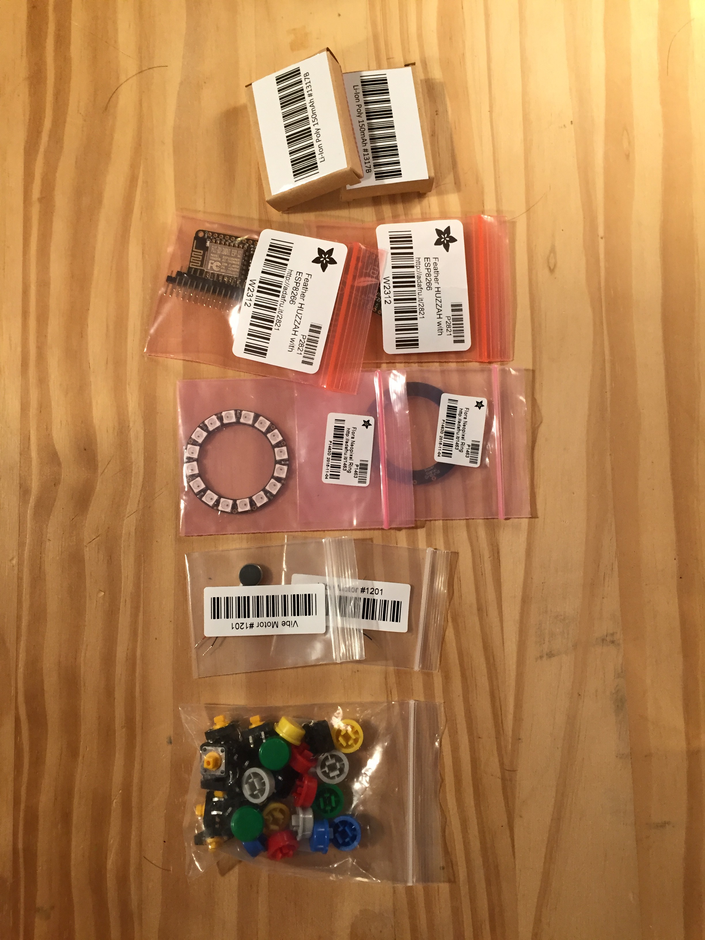
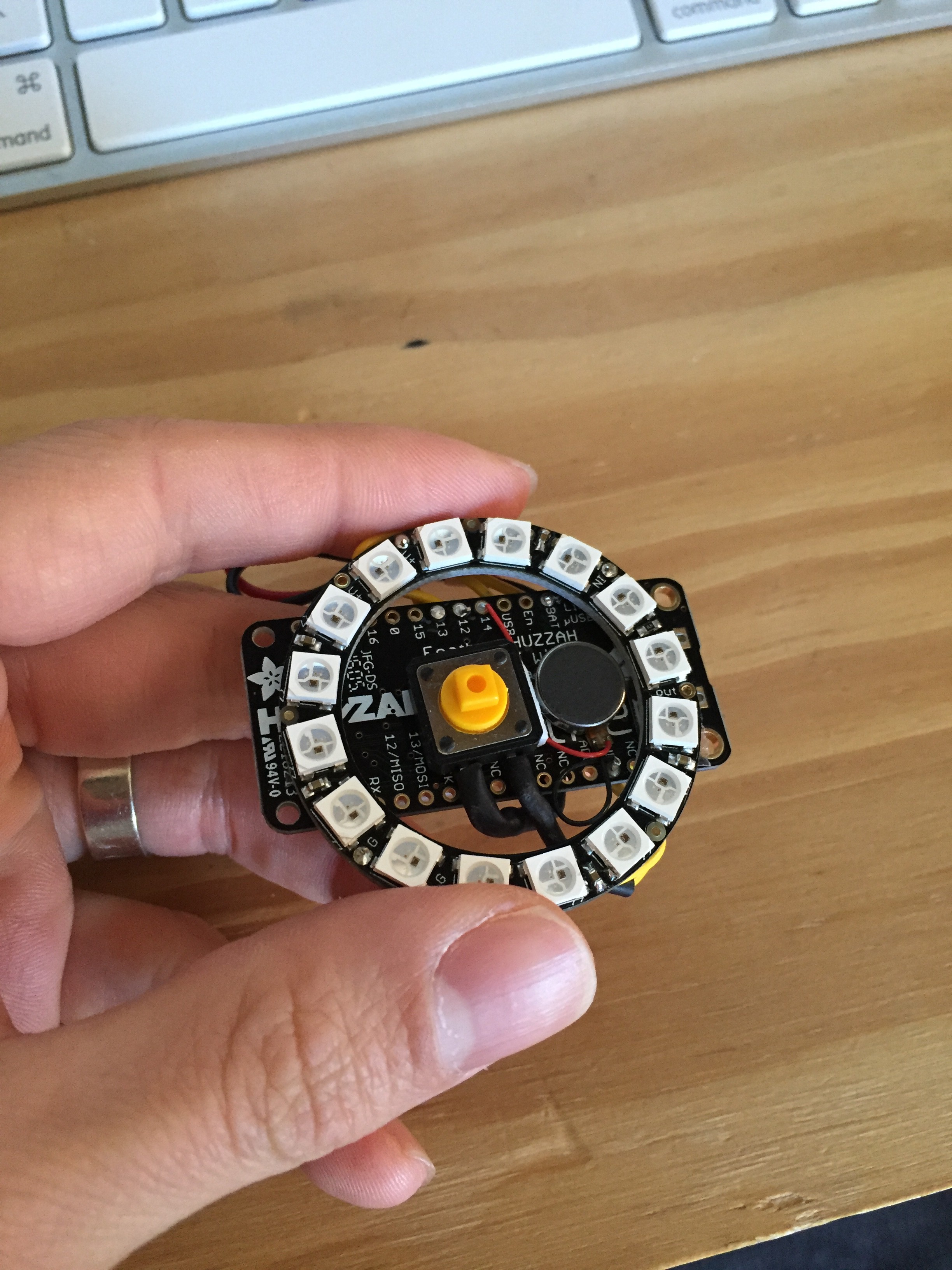
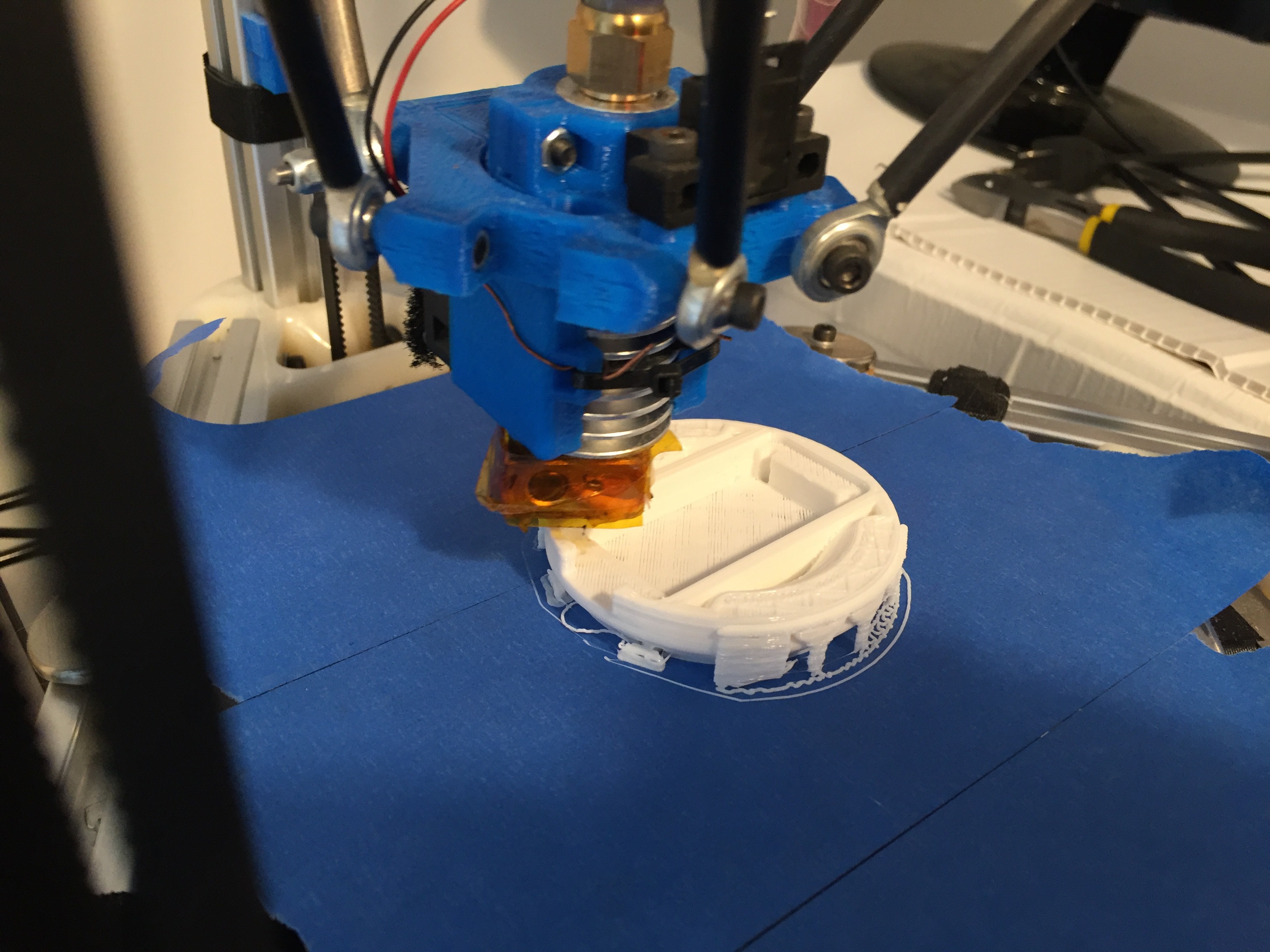
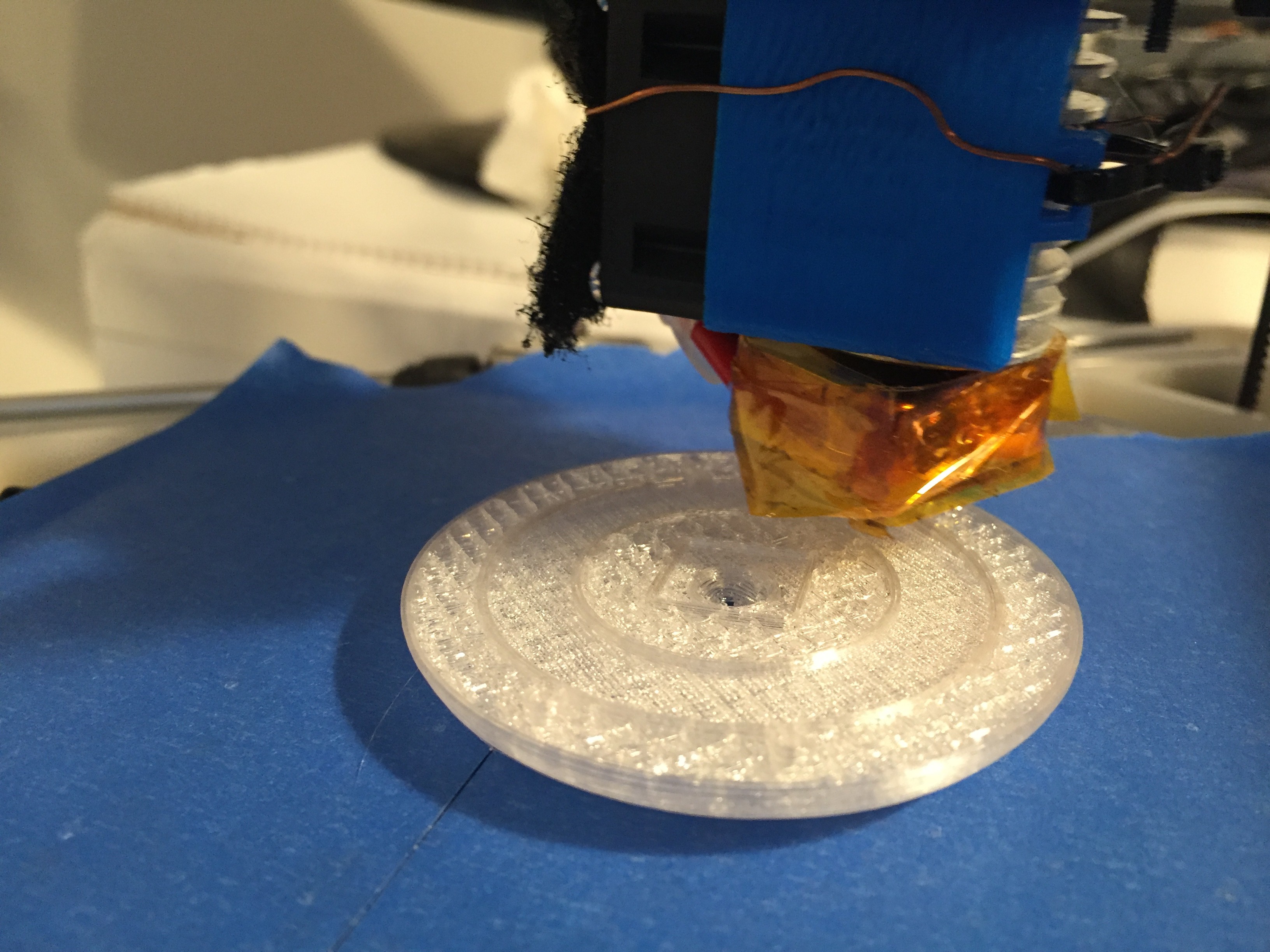
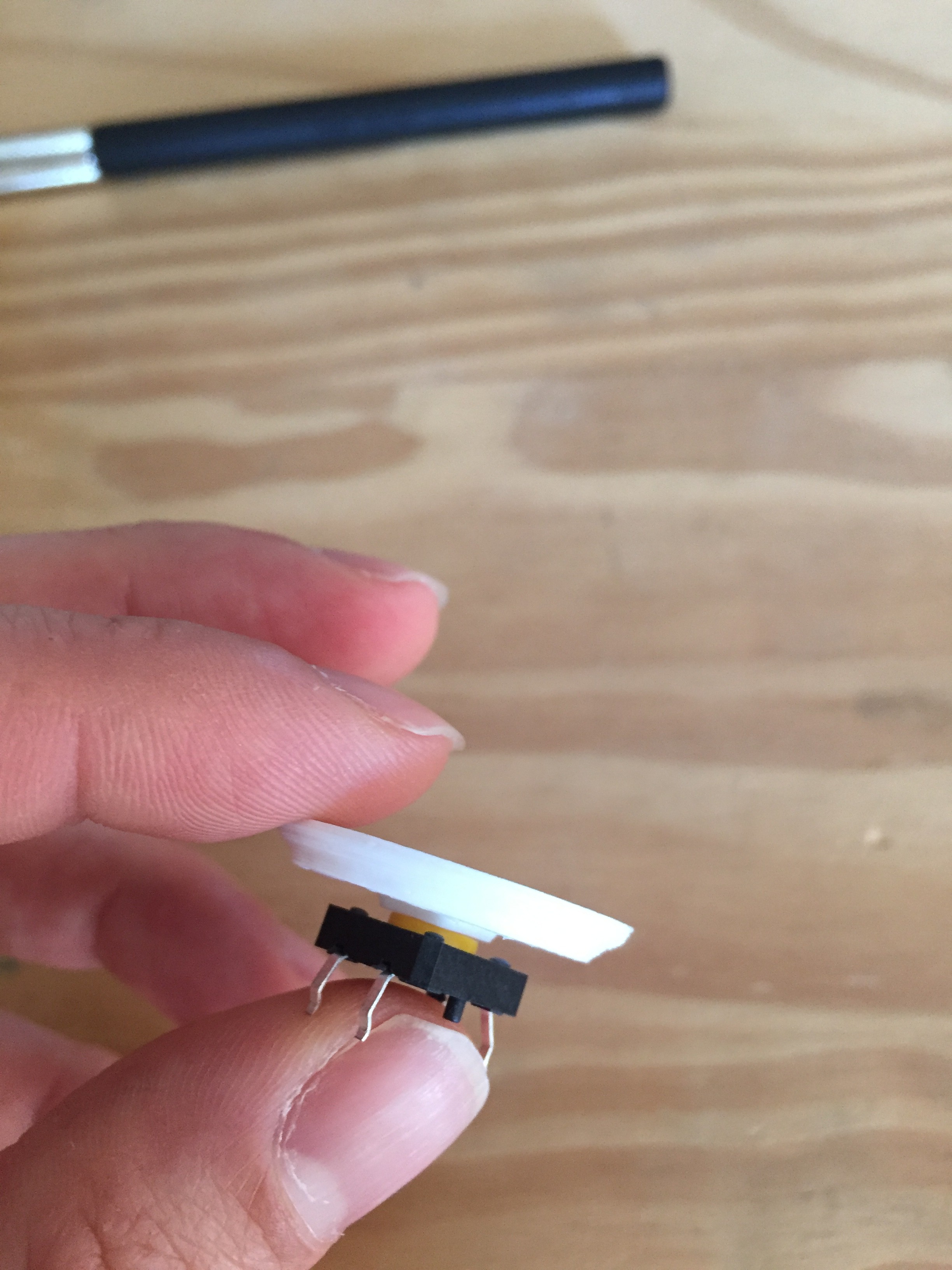
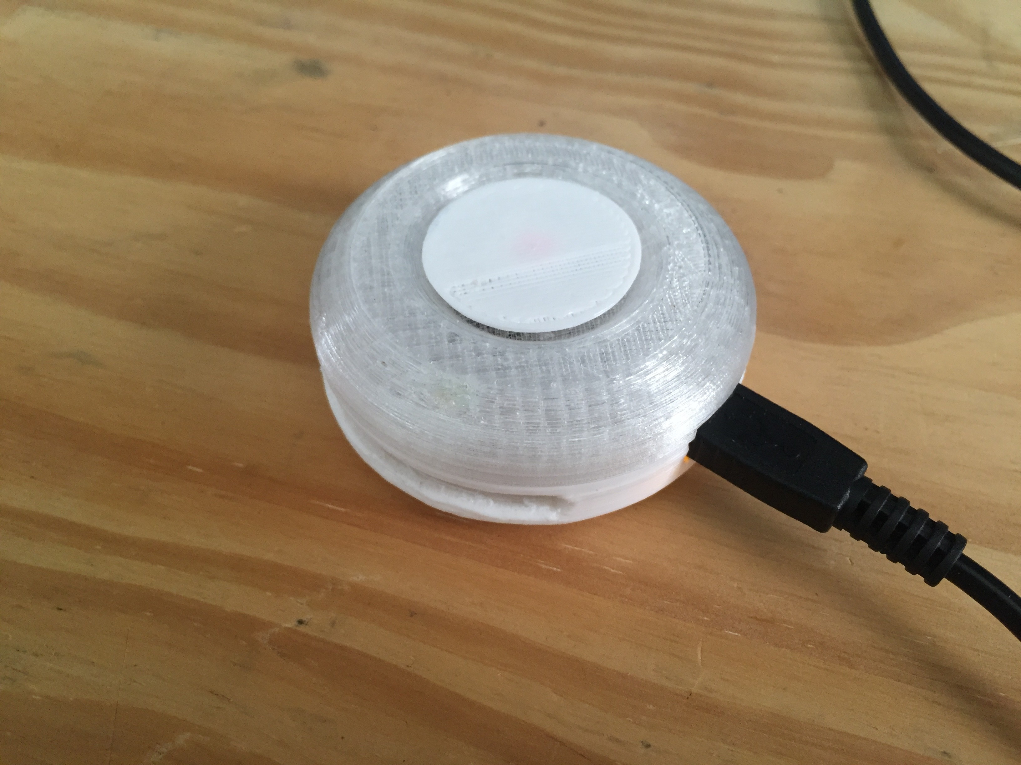
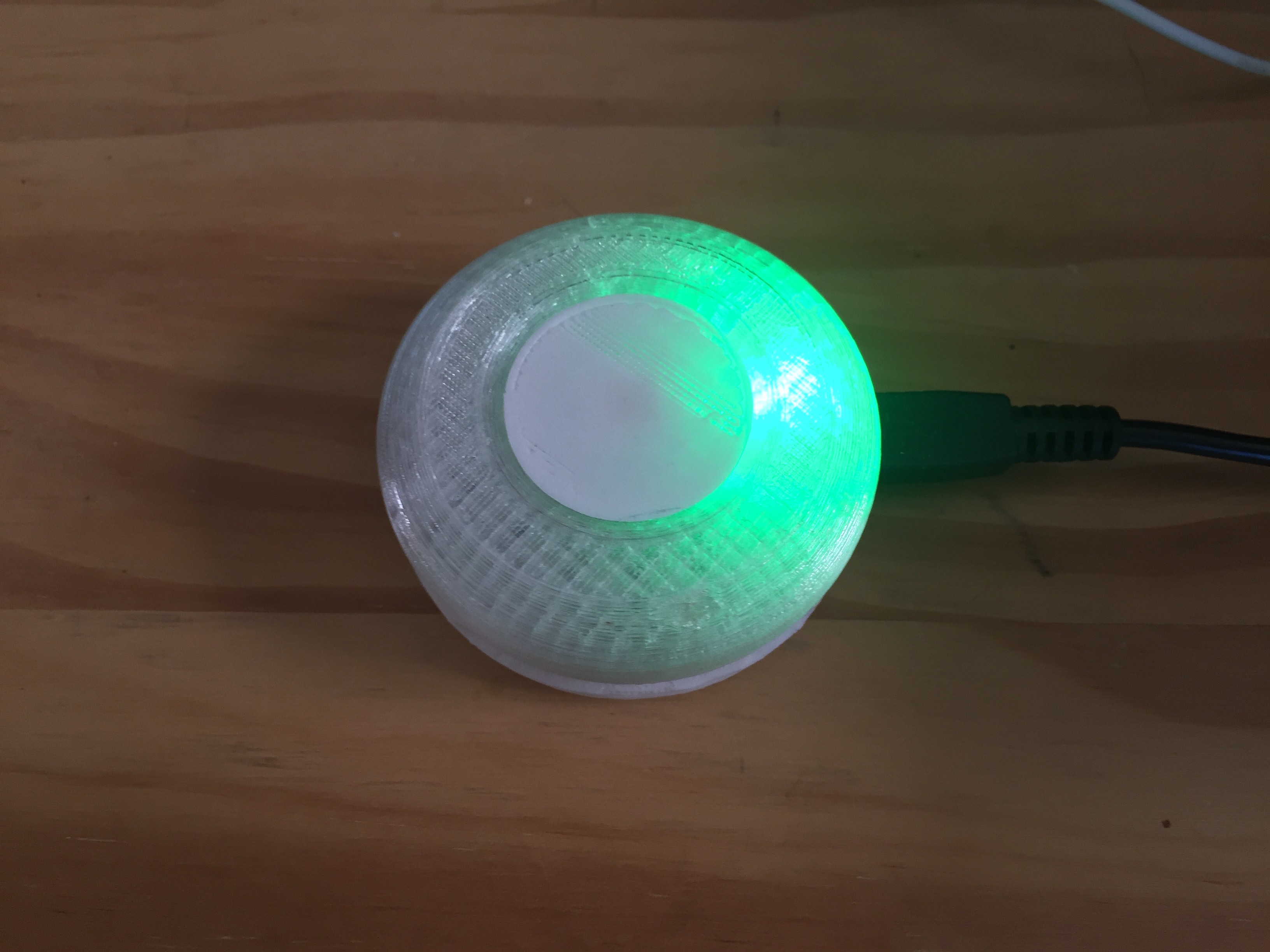
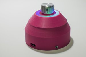
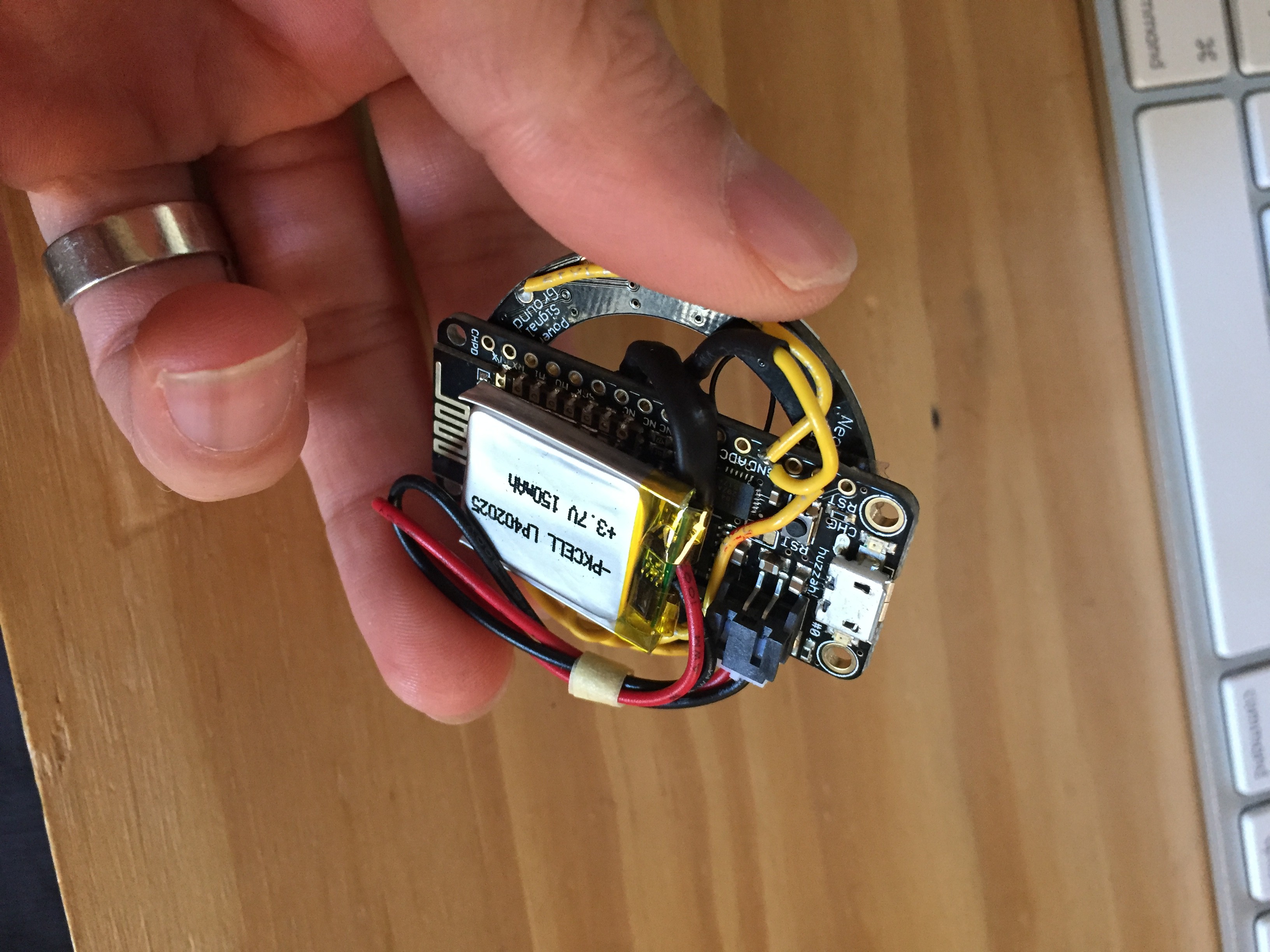 I'll be cramming this into a 3D printed shell for now; later versions will consist of a compact single custom PCB.
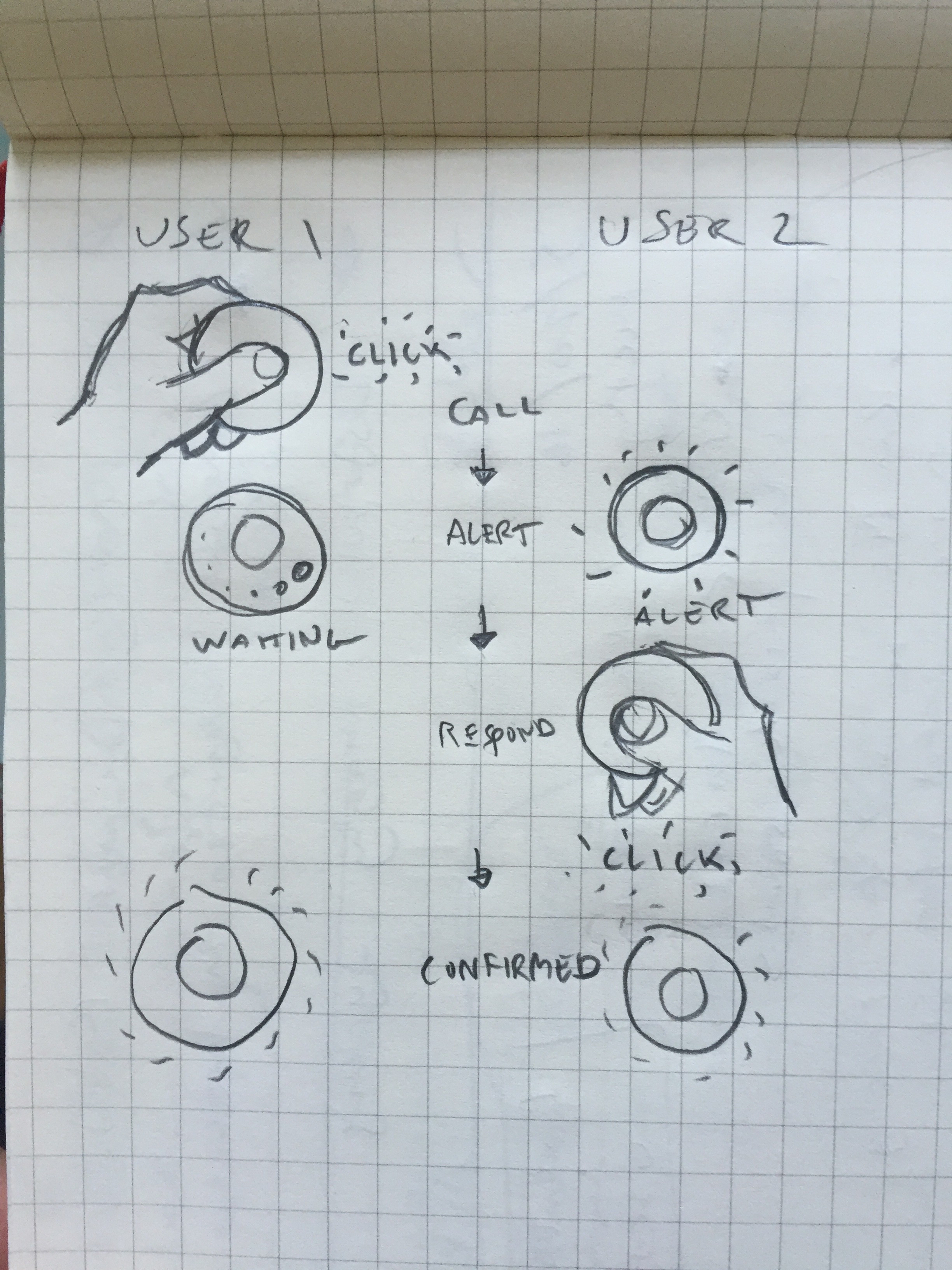


 Ákos Melczer
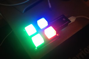
 Justin Maynard
 dariocose
 Minimum Effective Dose
Thank you man
https://packagejano.com/jazz-balance-save-code/