0%
0%
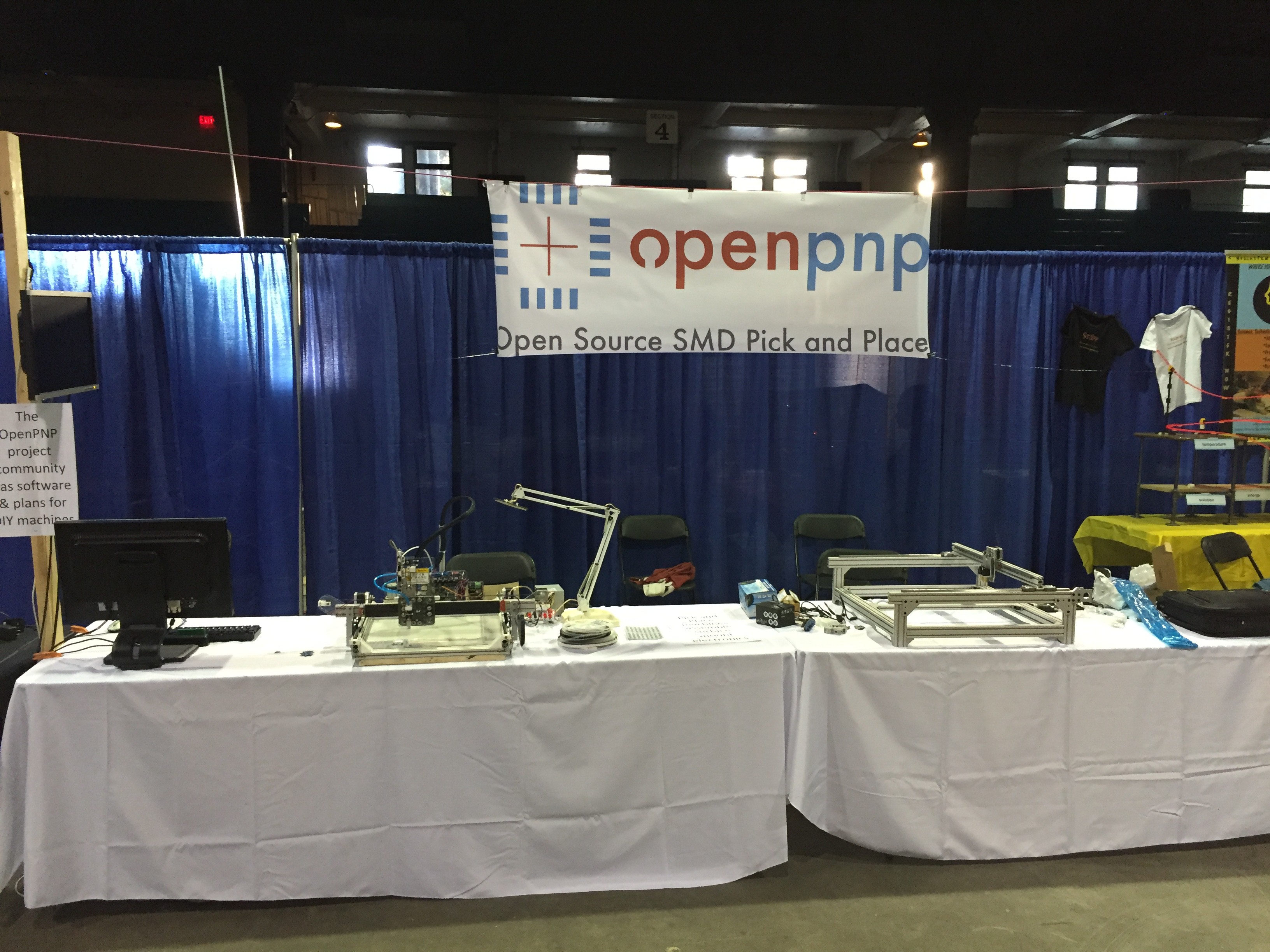
OpenPnP - Linear Rails
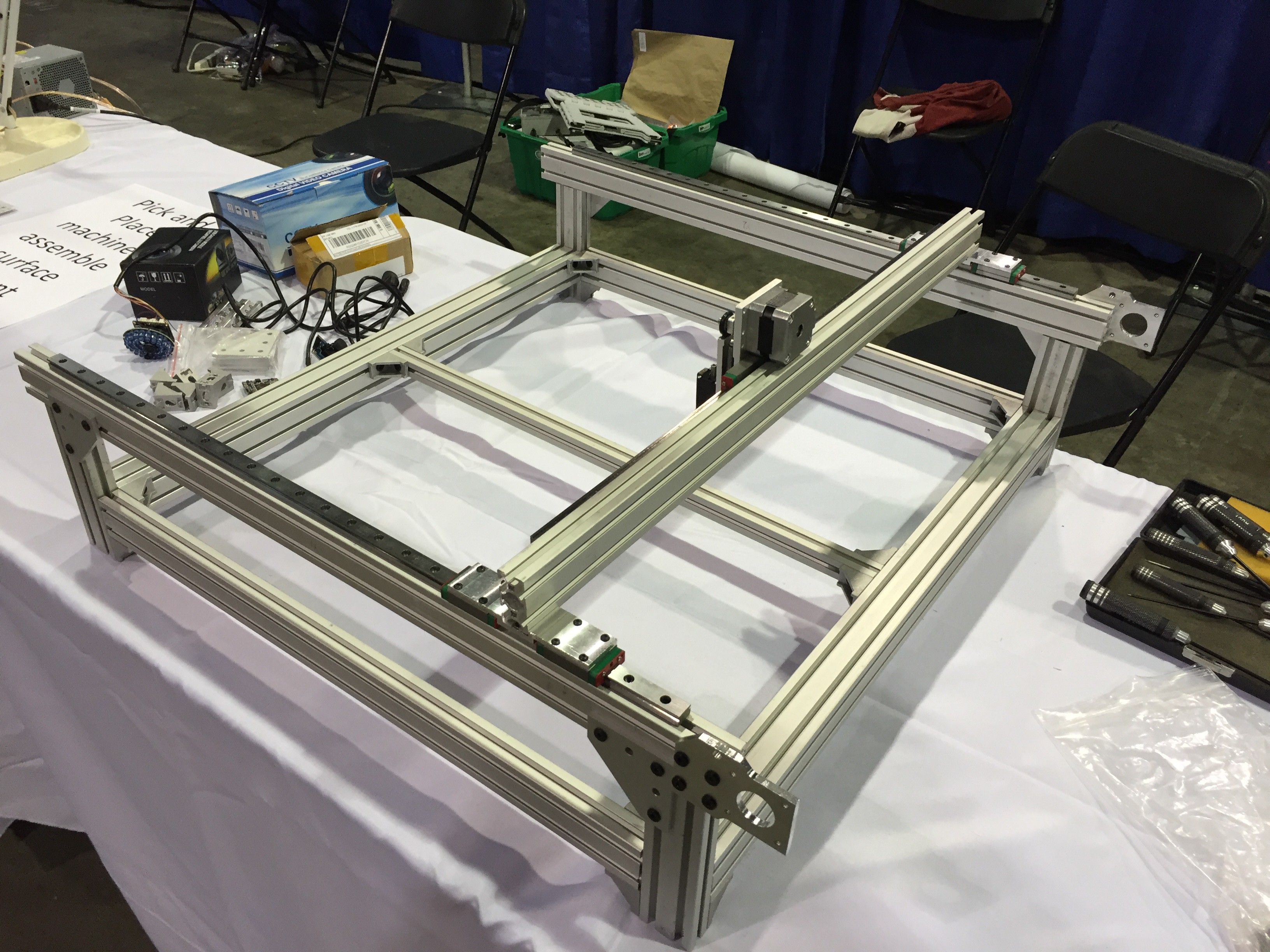
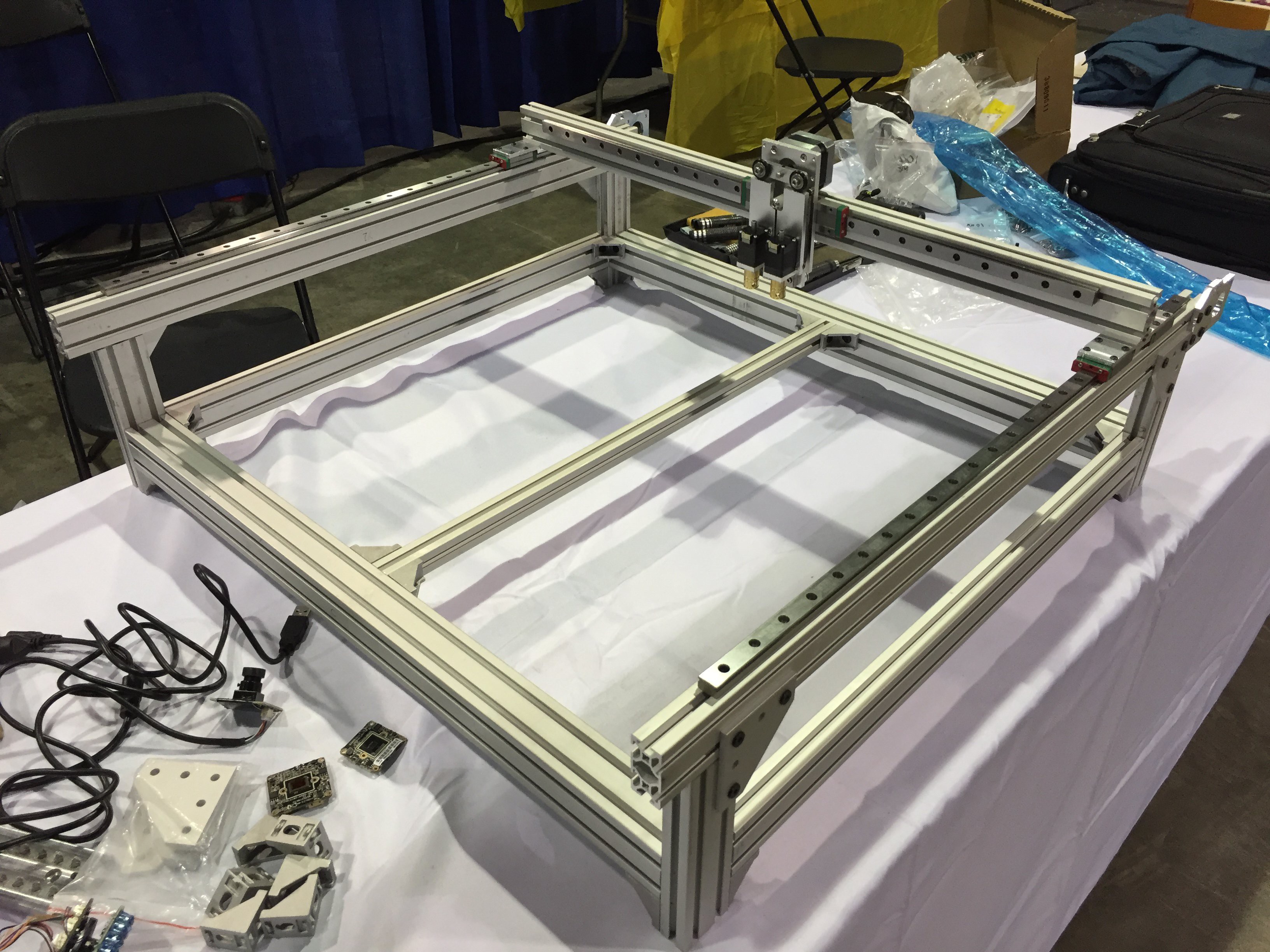
Open source pick-and-place machine utilizing linear rails with a cartesian X/Y gantry, built around the OpenPnP ecosystem
 Richard Sim
Become a Hackaday.io member
Already have an account? Log in.
Just one more thing
To make the experience fit your profile, pick a username and tell us what interests you.
Pick an awesome username
hackaday.io/
Your profile's URL: hackaday.io/username. Max 25 alphanumeric characters.
Pick a few interests
Projects that share your interests
People that share your interests


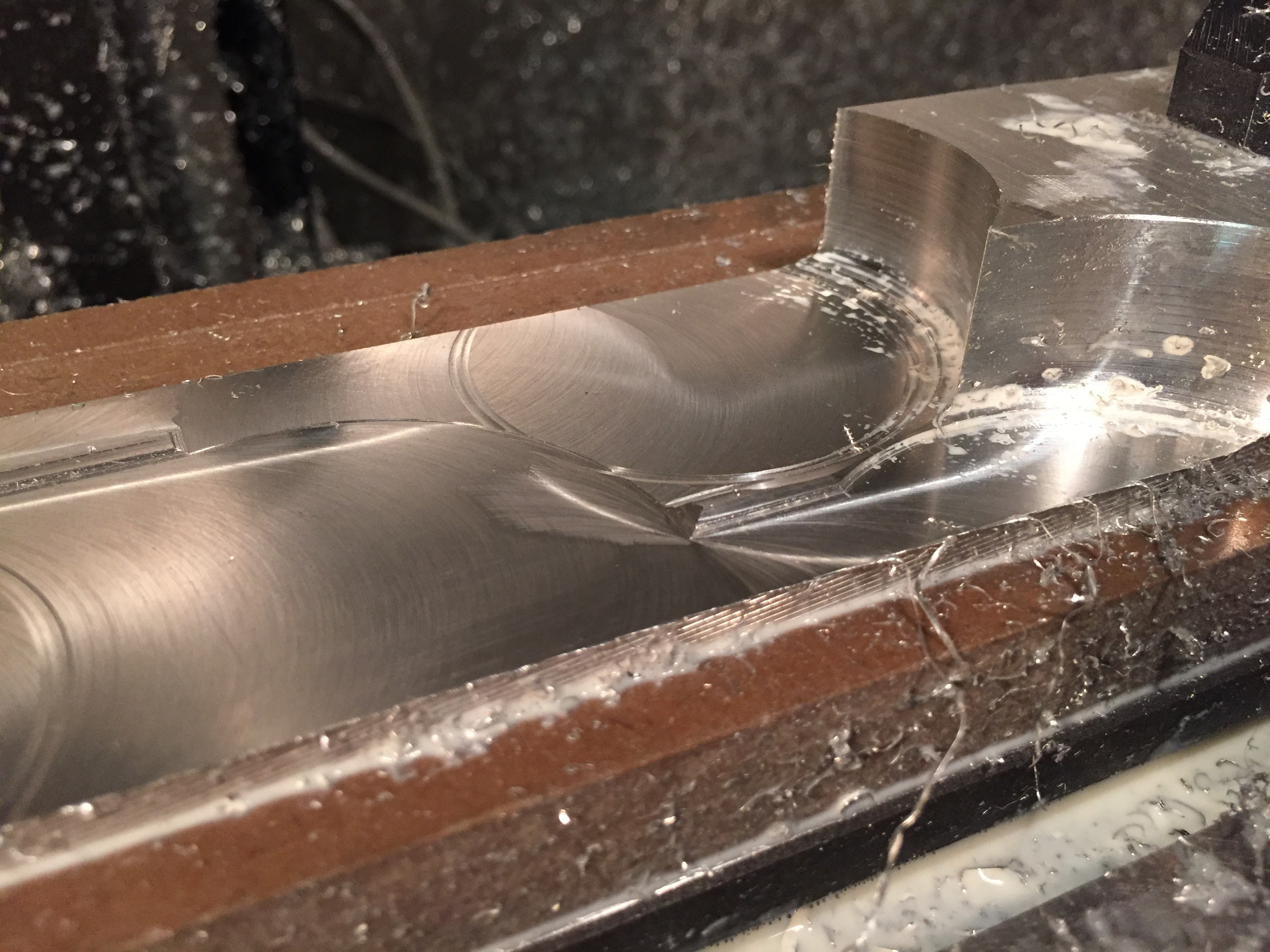
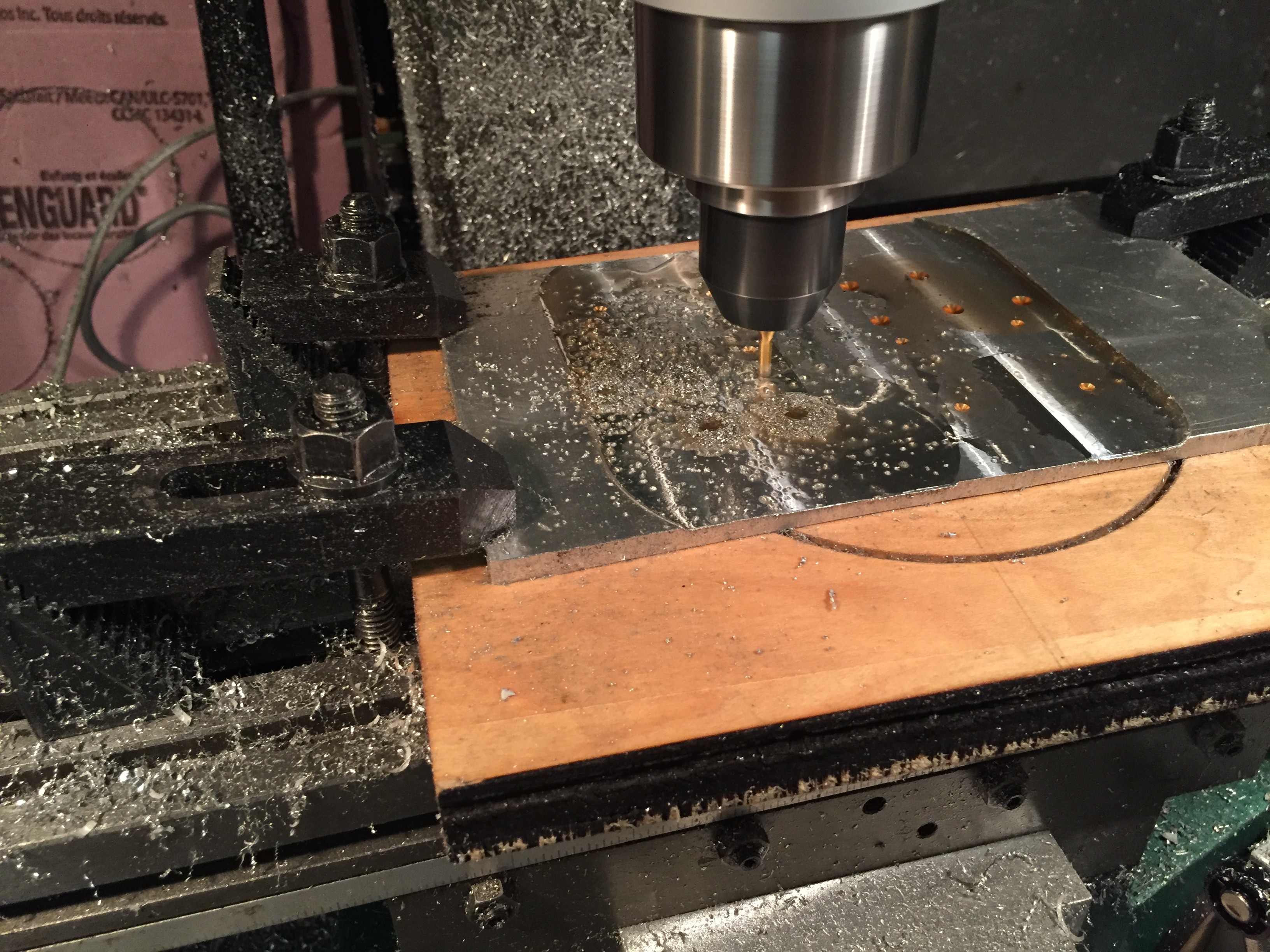
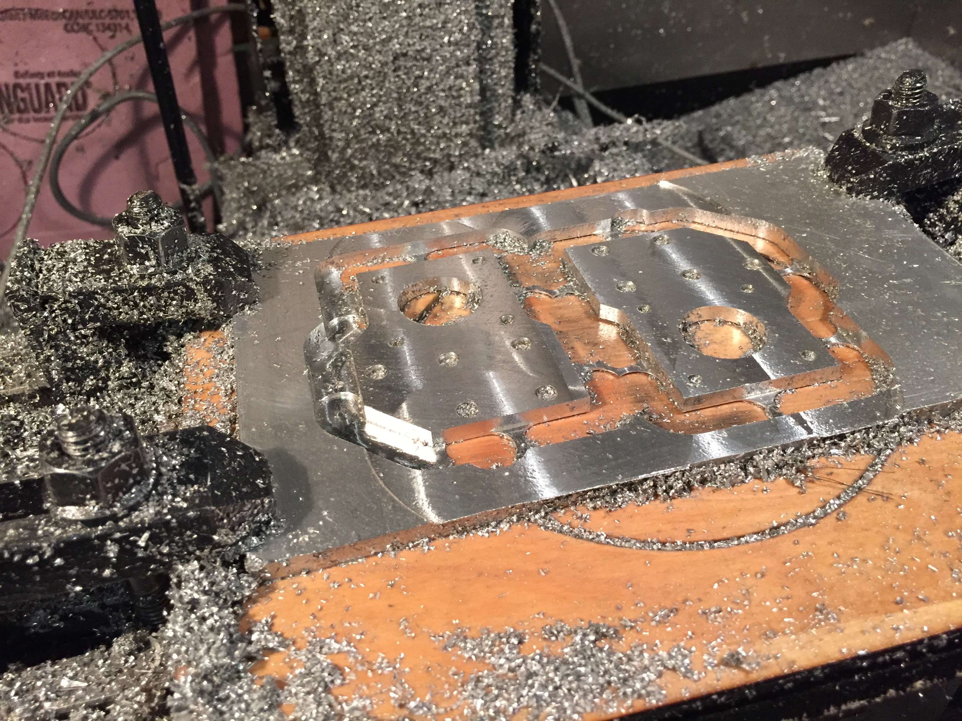
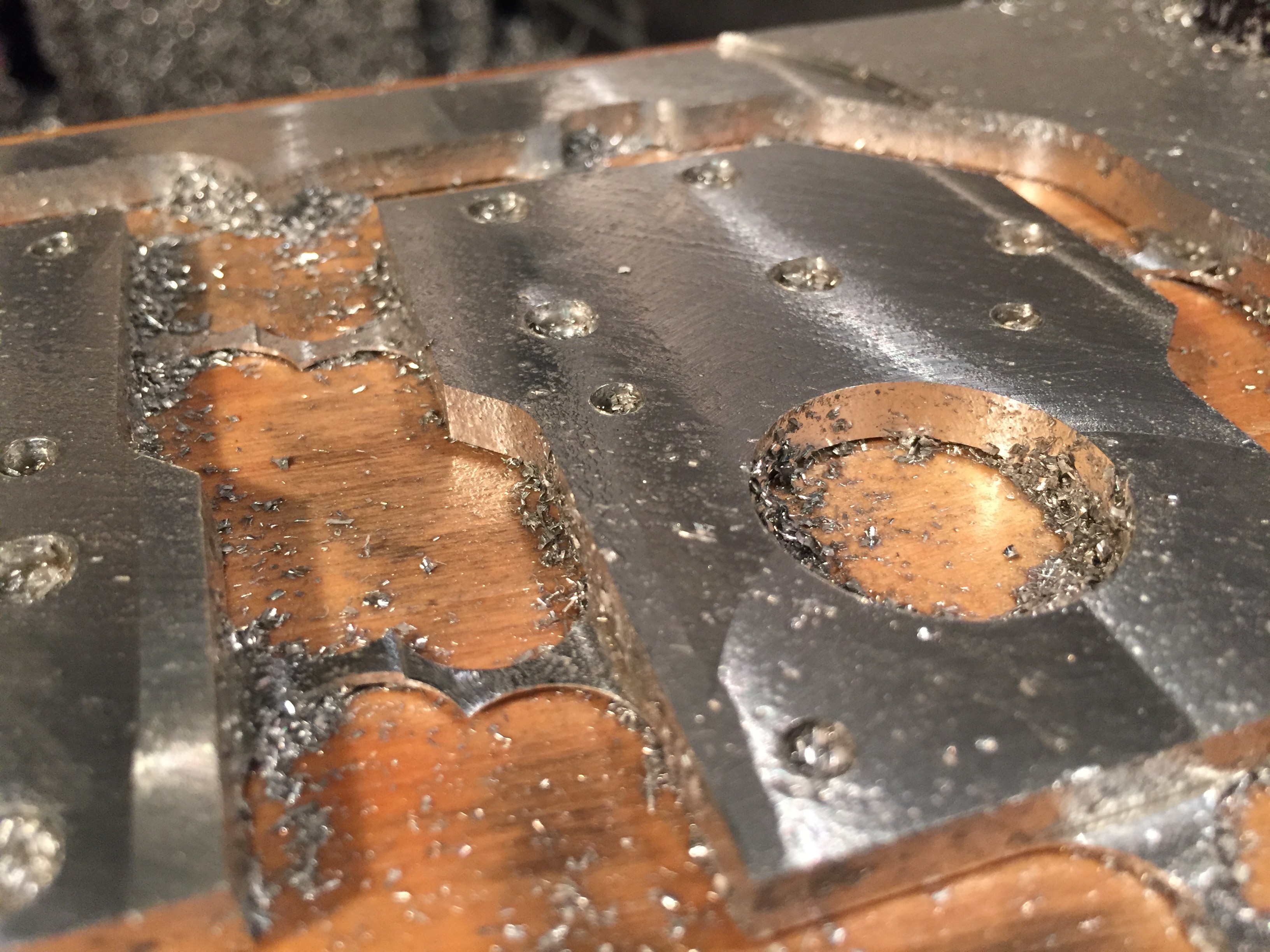
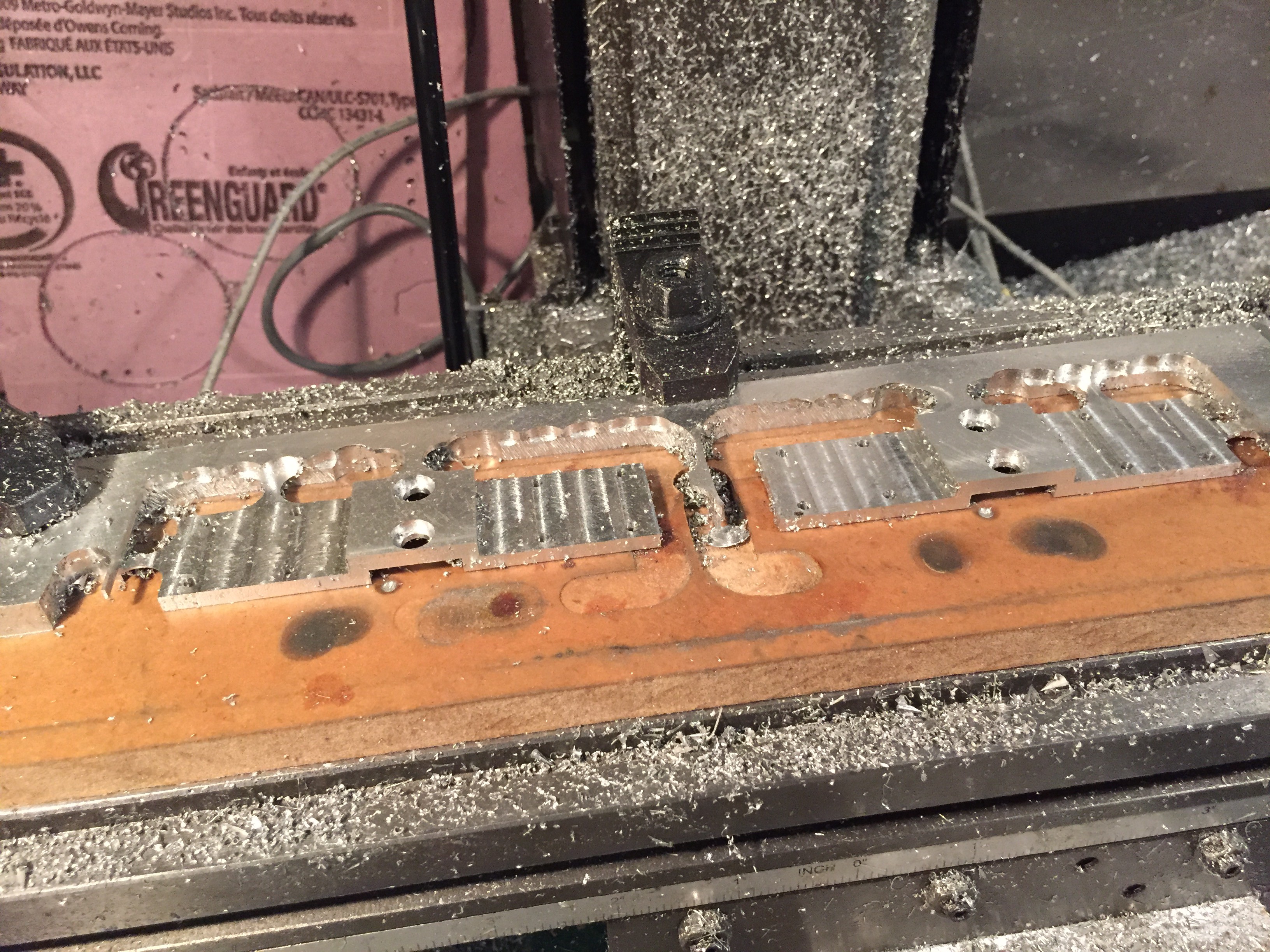
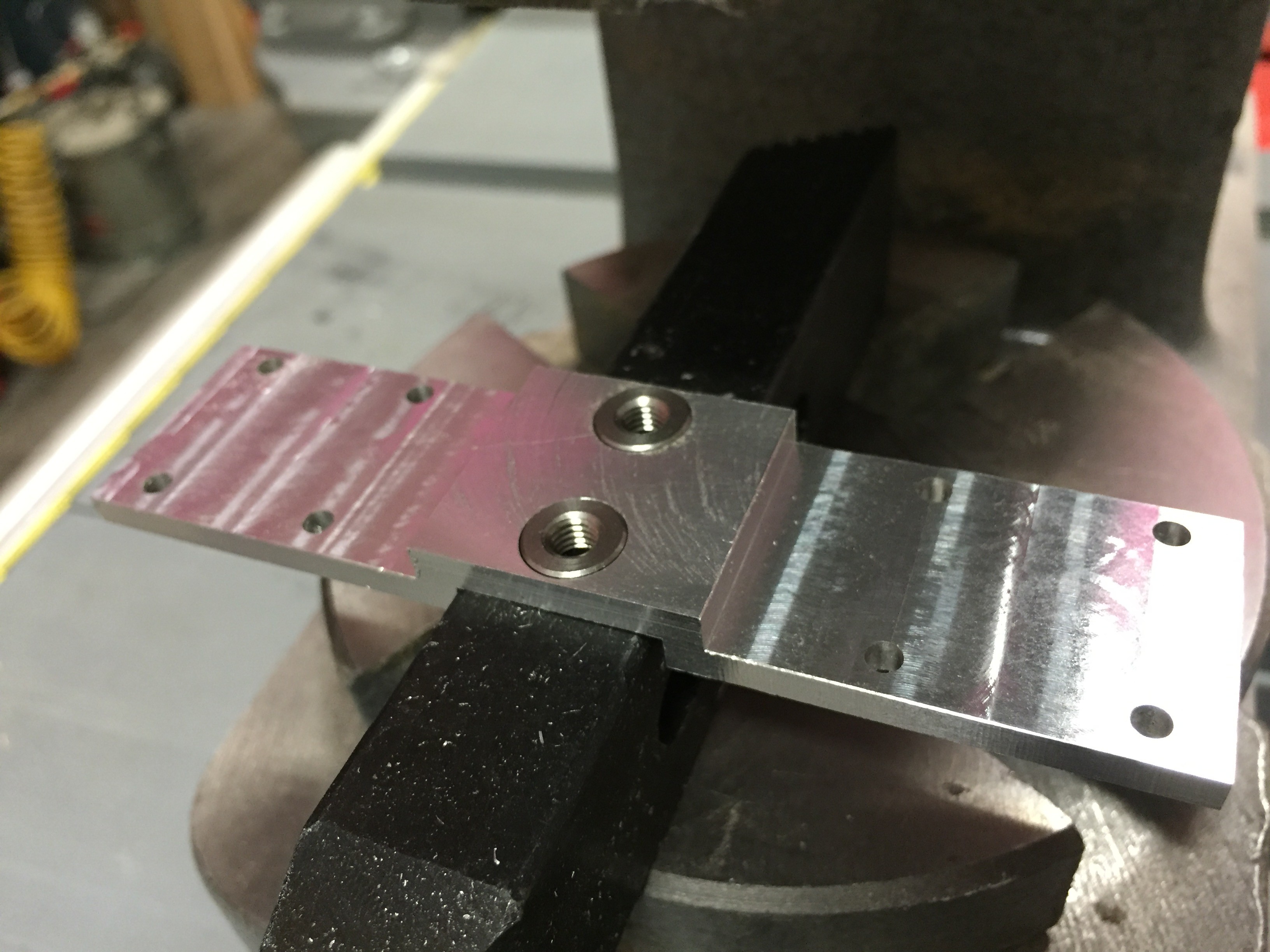
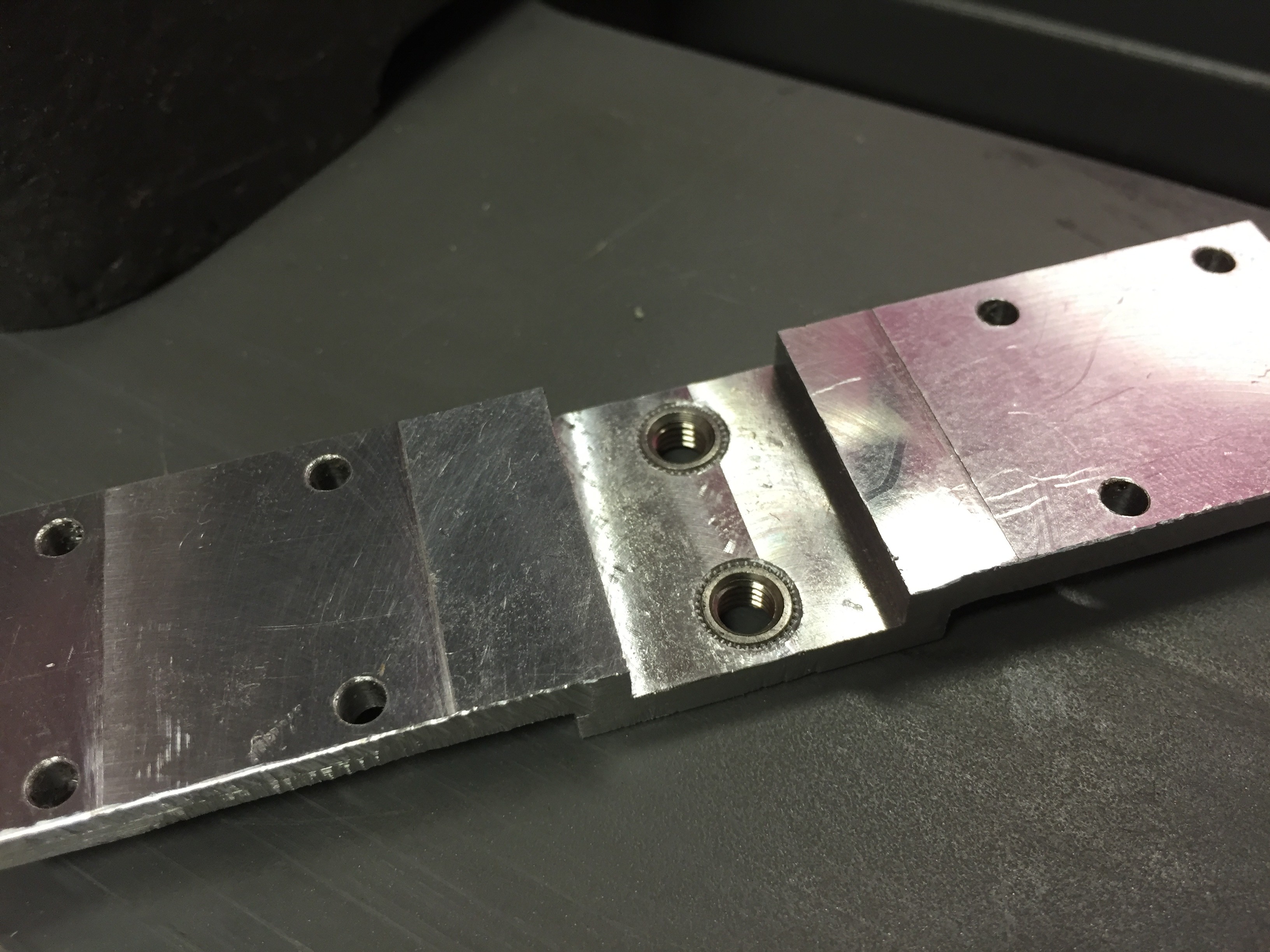
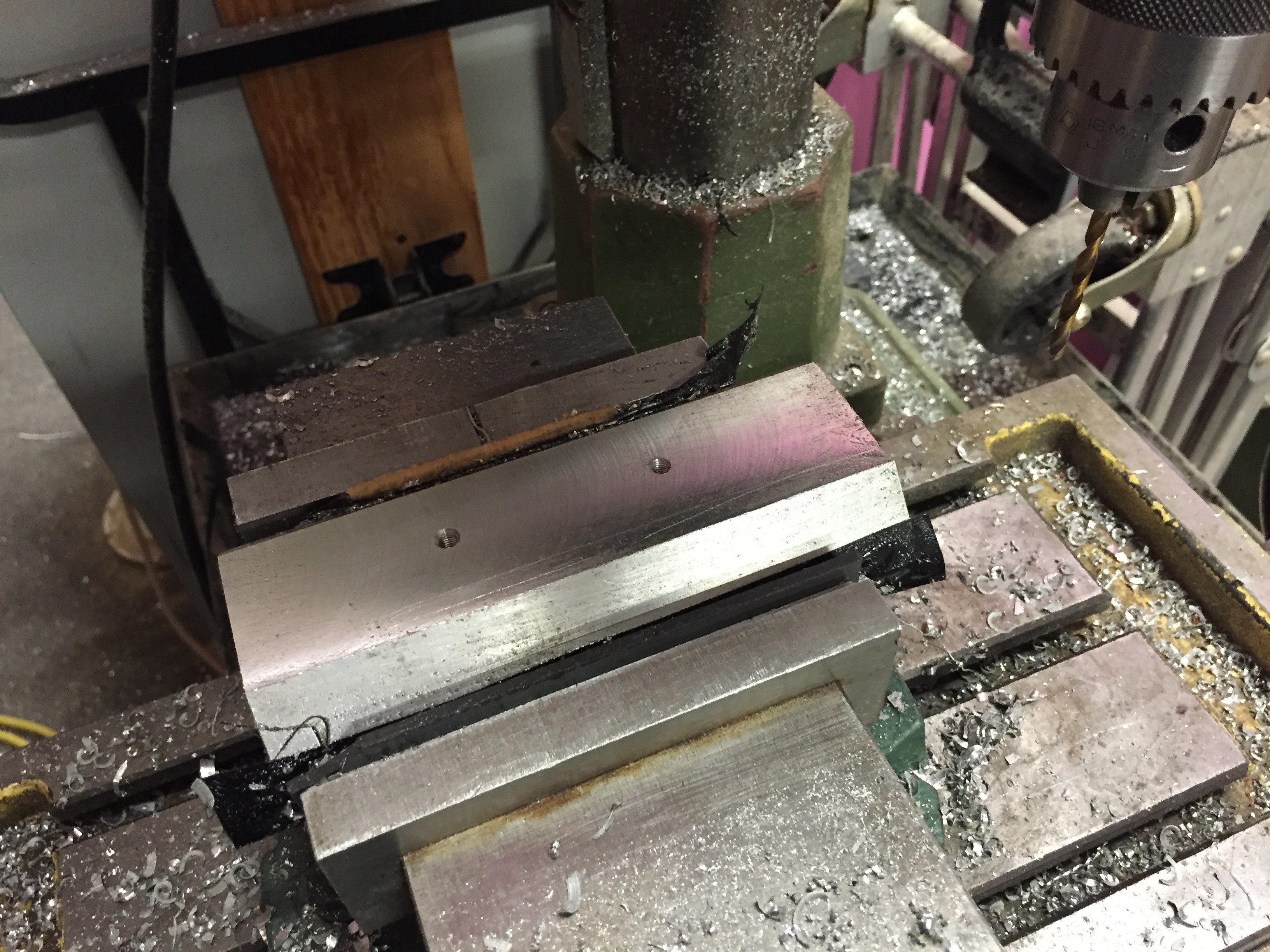
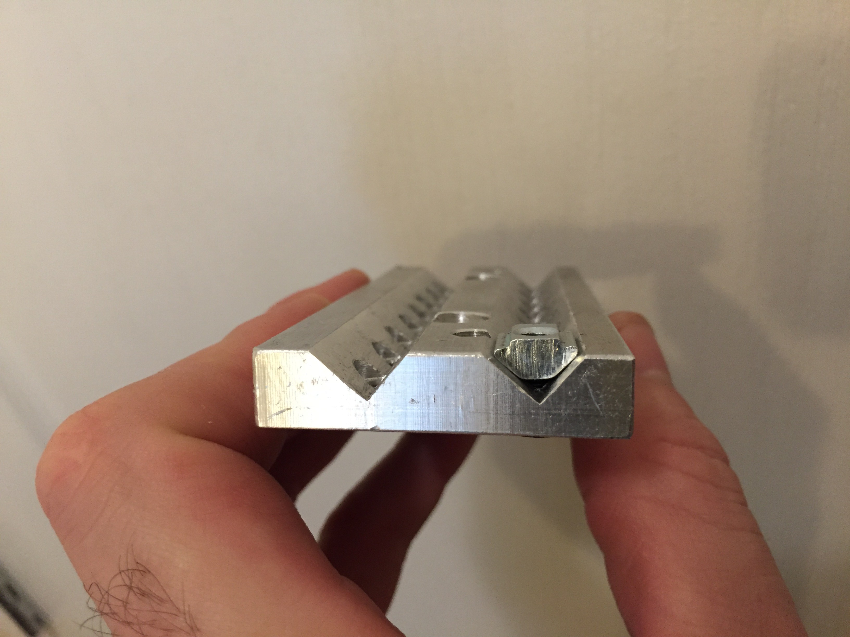
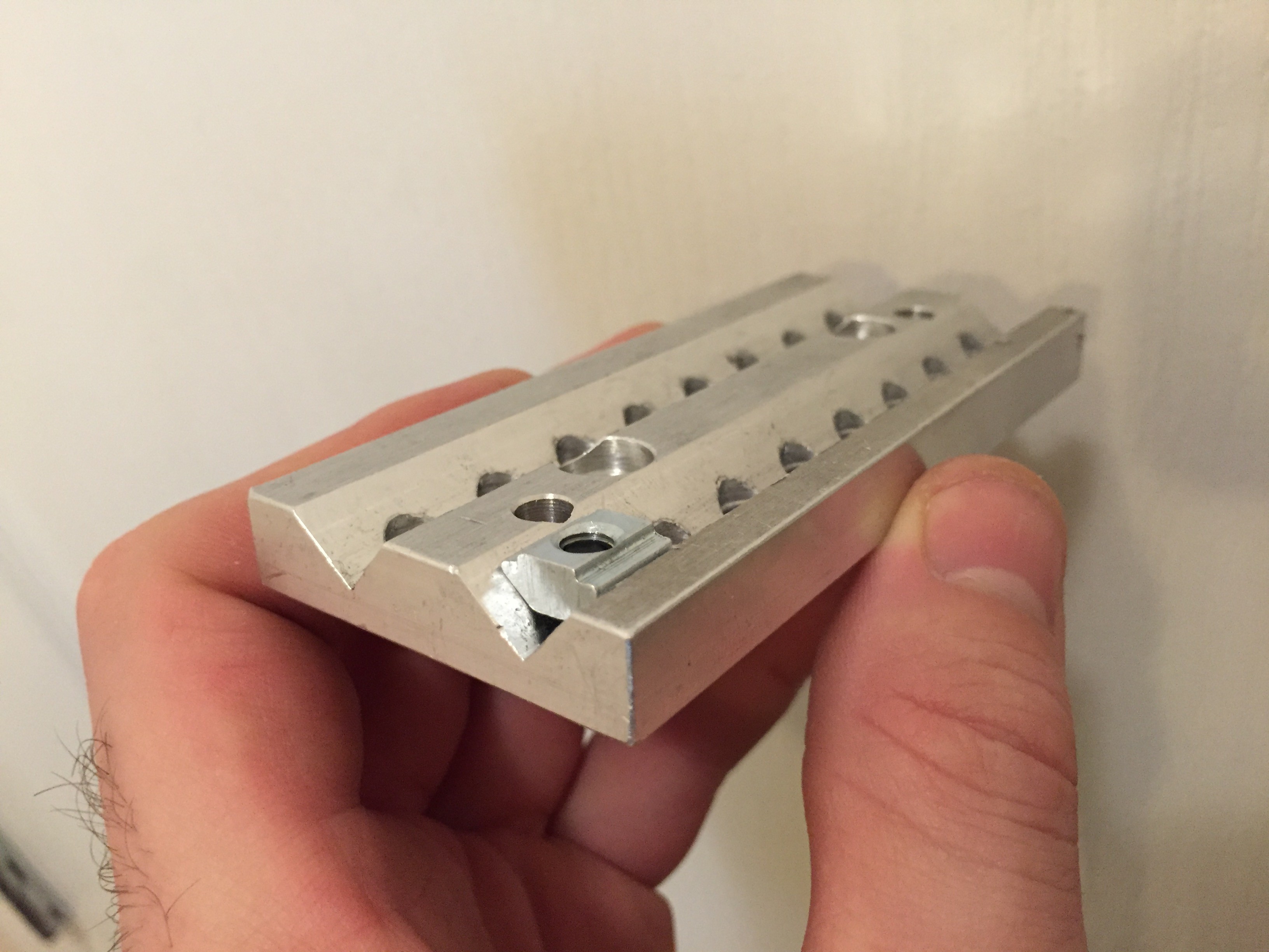
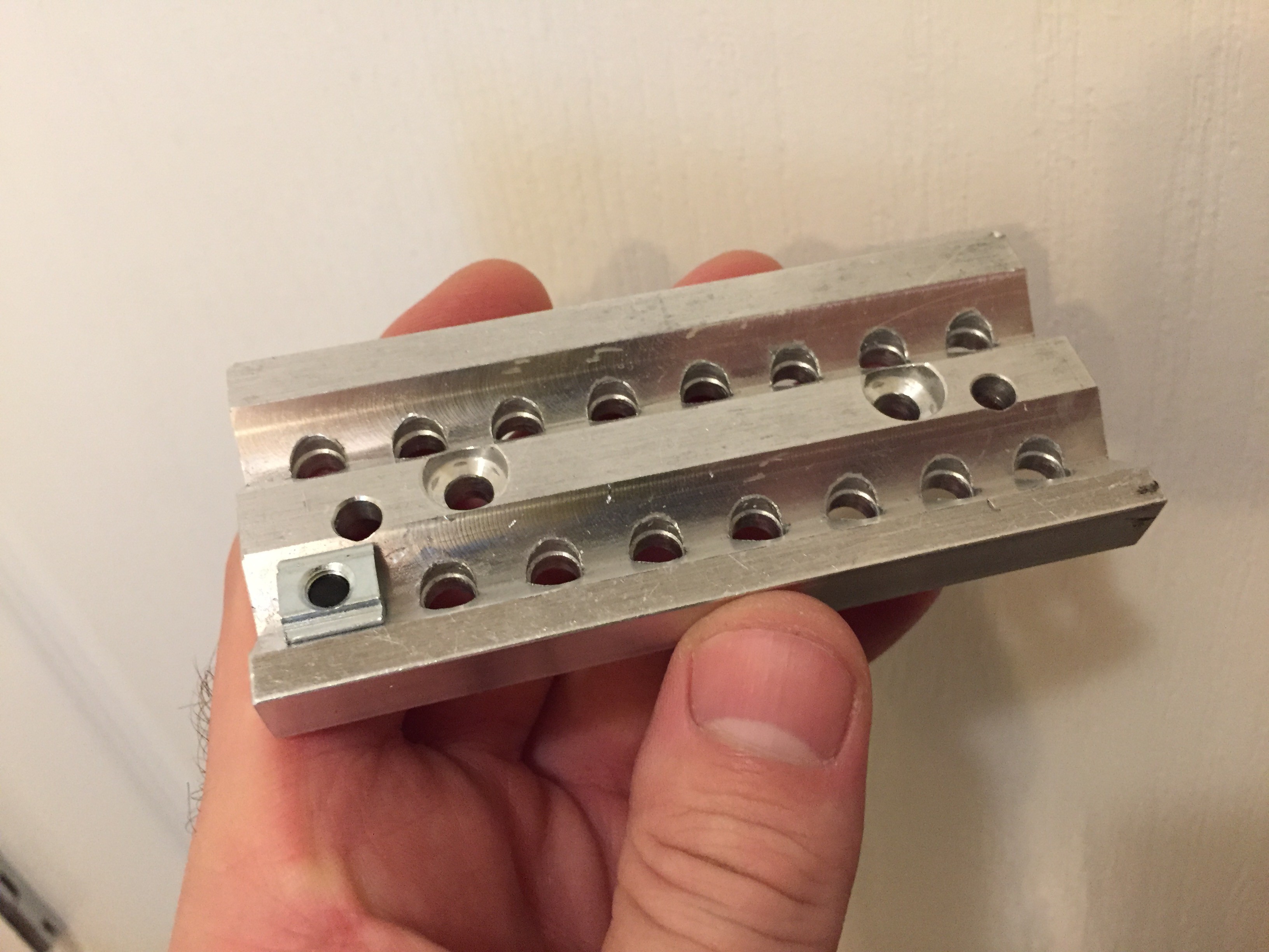
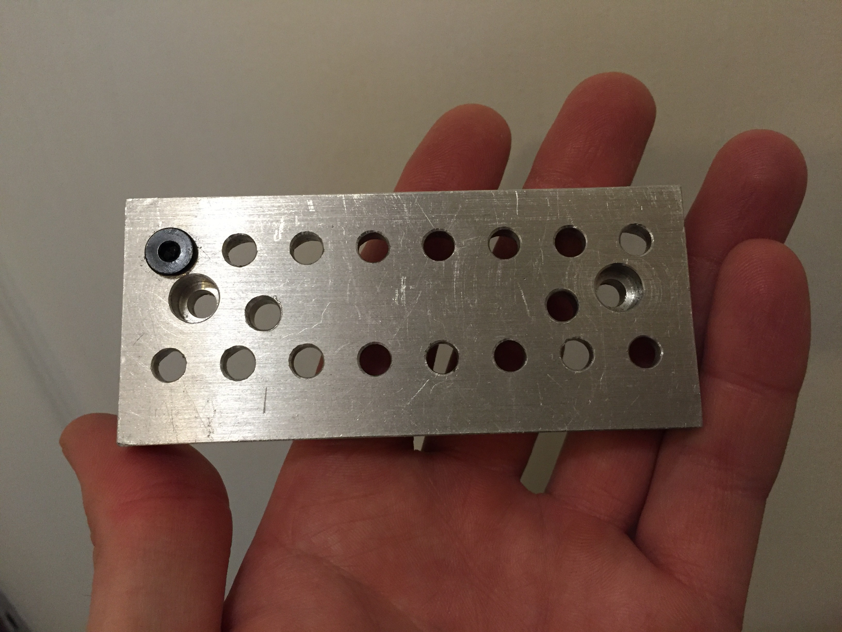
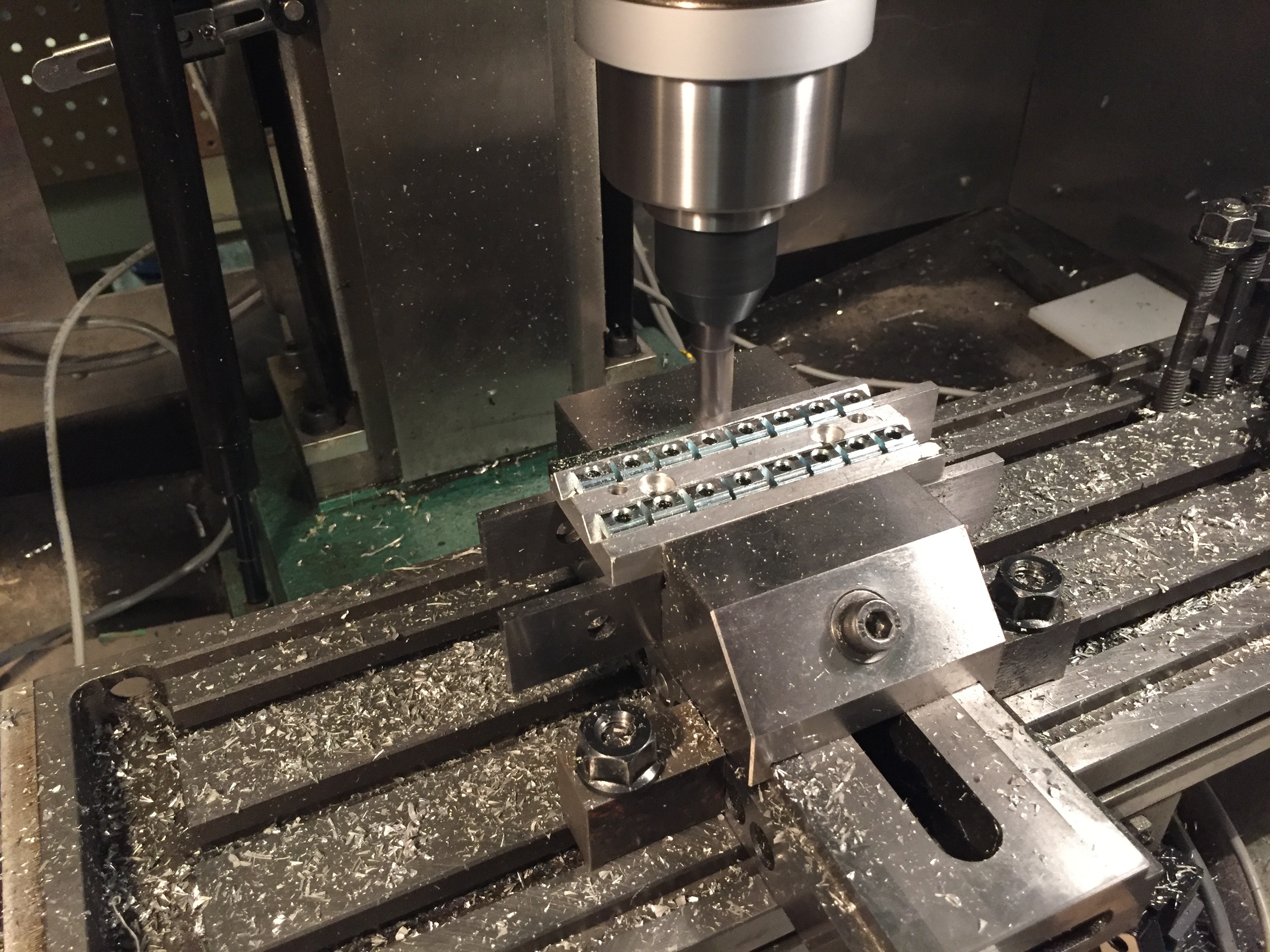
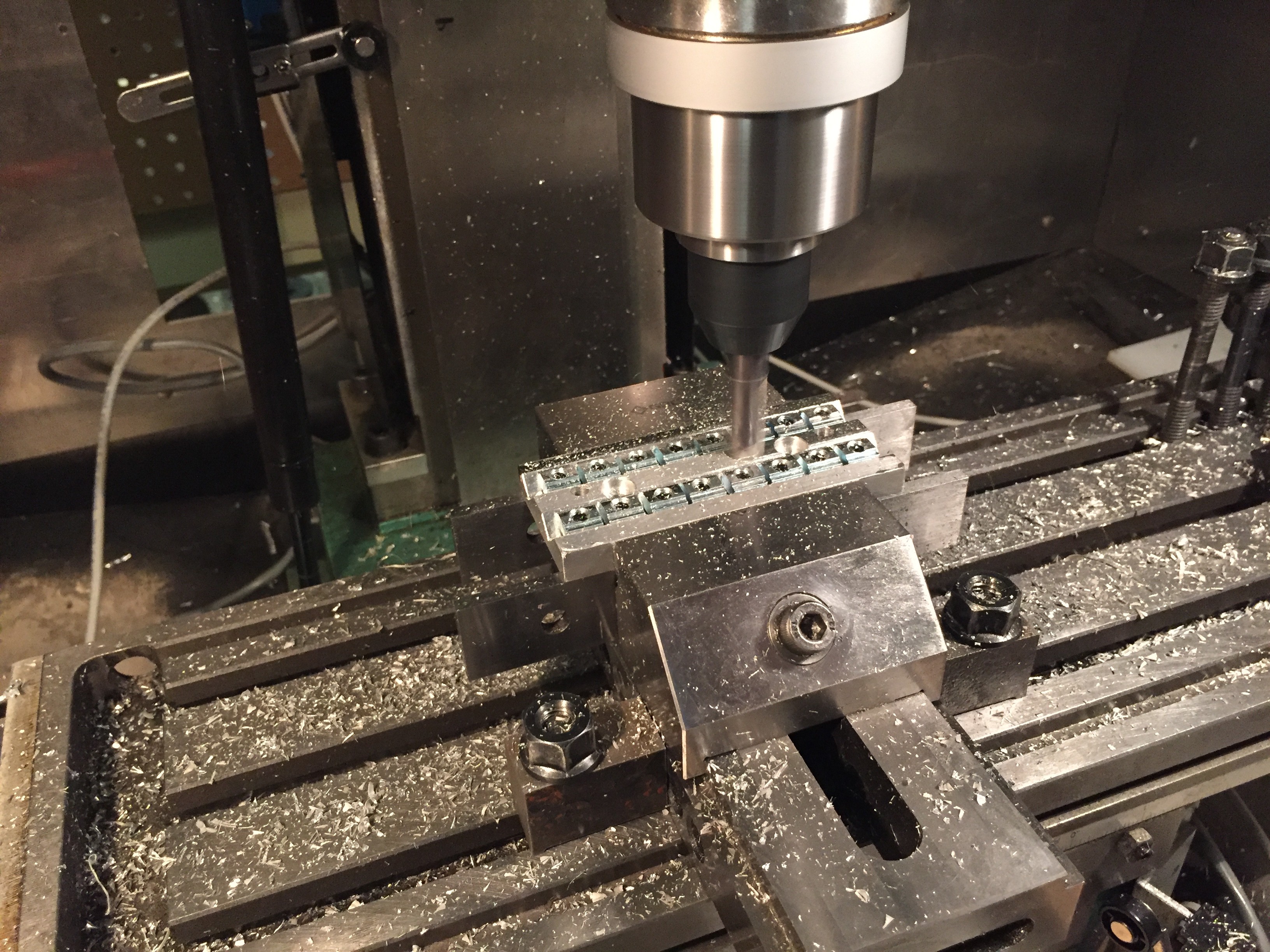
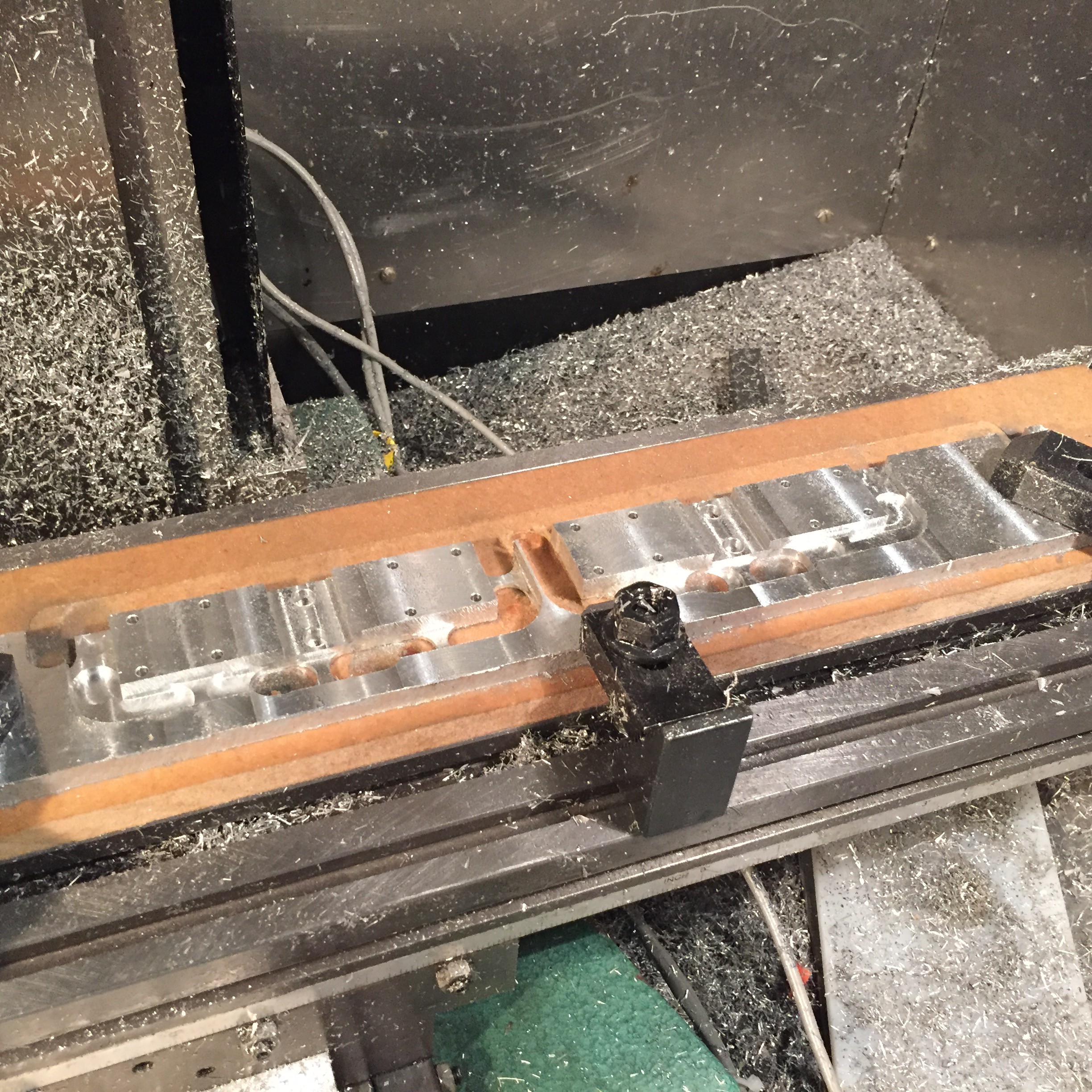 The part was then flipped so that the bottom side could be machined.
 Adrian Prinz
 Rui Caldas
 Federico Virdia
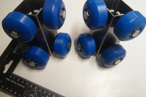
 morph
morph