 Ted Yapo
I read about this project on Hackaday this weekend. It's funny - I've read hundreds of Hackaday write-ups, and never really thought about the hours that went into each project until I saw my own up there. Impressive community of hackers. Thanks of course to @Benchoff and the staff there for the visibility and kind words!
Avast, Ye Hackers!
I stayed up late last night and wrote a python driver for the MLX90393 using the SPI binary scripting mode of the Bus Pirate board (from Sparkfun, and of course, [Ian]). One of the difficulties is that the MLX90393 requires a hardware line to signal the master when conversions are done; there's no way for software to poll. This probably makes sense during sensitive magnetic field measurements, since polling by the master could only serve to distort the field. For now, I'm using generous delays set according the the expected conversion times listed in the datasheet. Using the Bus Pirate will probably be good enough until I get the final sensor head designed and built. At least I'm getting data. You can check out the code over at GitHub.
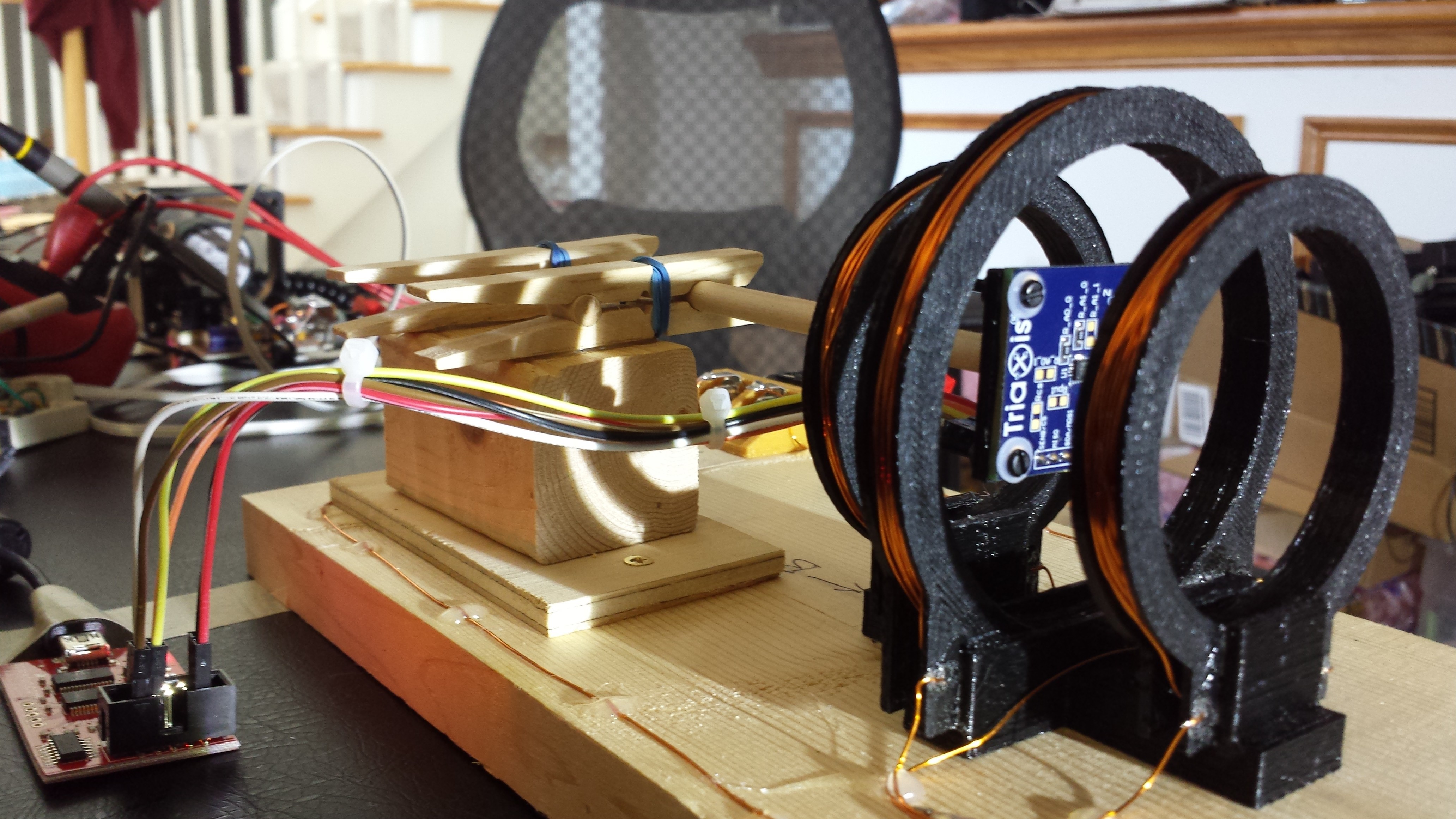
I printed a simple mount to attach the MLX90393 evaluation board to a 1/4" wooden dowel, and found some non-magnetic header pins to solder on the board. The mount holds the EVB with nylon screws and nuts. Here it is in the coil, connected to the Bus Pirate with short jumpers - I'll need to make some longer ones to scan some test fields with this part. As you can see, the EVB is huge (30x30mm), even though the MLX90393 itself is only 3x3mm, and doesn't require any external parts. I'm going to throw in a bypass cap on the final sensor head, even though the datasheet would have you believe it's optional.
The first data I collected was a repeat of the HMC5883L tests run earlier. Here's the first graph, comparing the reported z-axis component of the field with the field calculated from the current and Maxwell coil dimensions:

This is more like what we want to see! The scaling is based on calibration values provided in the datasheet: the only correction applied to the data was to subtract off the zero-current reported field (25.87 μt) from all data points. The linearity is clearly there, but the scaling is definitely off. At this point I don't know if:
- the scale factors in the datasheet are incorrect
- my Maxwell coil or calculations are off
- this part just needs to be calibrated before use
To get a better feeling for the issue, I did a regression fit to find the scale factor, and then replotted the data (this assumes the coil is correct):
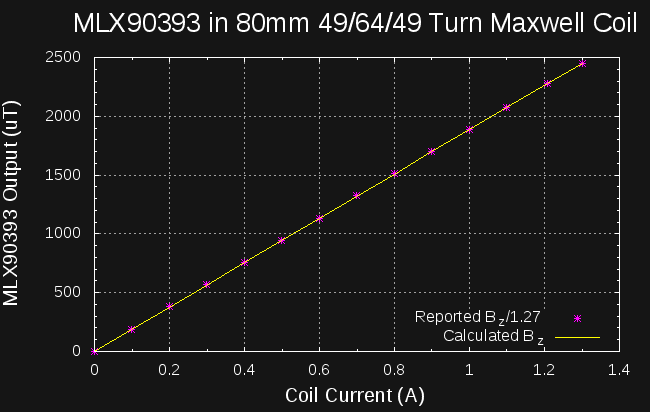
Much better. The best-fit scale factor is 1.27, which, maybe out of pure coincidence, is almost exactly one "GAIN_SEL" step in the MLX90393. I've poured over the code and poked around registers for a while now, and can't find where I'm screwing this up. I did find an error in Table 4 of the datasheet (on the same page as the scale factor table), so it's possible the scale factors in the datasheet are also incorrect. Specifically, the offset for the {RES = 3, TCMP_EN = 0} case is 2^14, not 2^15 as shown in the datasheet. I noticed the error after testing with these settings produced clearly wrong values, and I was able to confirm the error in Table 4 by comparing it to the "MLX90393 Getting Started" application note. I haven't found a similar error for the GAIN_SEL parameter, though. Unfortunately, Melexis' web site appears to be in a state of flux: the links to their datasheets and appnotes were broken for the past few days, and today their entire site is 503. When they come back on-line, I'll see what other clues I can dig up.
The driver doesn't implement temperature compensation yet, since I couldn't download the relevant application note, and that information is missing from the datasheet.
In any case, it looks like we have a winner with this sensor - it's nicely linear to the limit of my first calibration set-up.
50mT in a Maxwell Coil?
If I had been paying attention to my own logs, I would have seen this earlier. The maximum full-scale range of the MLX90393 sensor is around 50mT. The field in the Maxwell coil is:
Plugging in 50mT for the field and 40mm for the radius, we find that we need a current of about 26 amps. In the 3-ohm coil, this would dissipate over 2000W, melting the PLA coil form a few seconds before melting the windings themselves. It actually sounds fun, and I do have a pair of 40V Li-ion packs for my electric string trimmer that might be able to produce that much current, but it's not a practical way to test the sensor range...maybe once I have a better coil this one can be sacrificed in the name of science.
What I really want to see is what happens when the MLX90393 is exposed to fields greater than its full-scale range. Does the output saturate at full-scale, or does it fold over and produce bad data like the HMC5883L? I think I'd be OK with calibrating the sensor in the low-end of the range and extrapolating to full-scale calibration as long as the part saturated properly.
To test for full-scale saturation, I'm working on a little rig to accurately position a rare-earth magnet near the sensor. A little more time in the shop and I should be ready to collect some data.
Auto Ranging
The MLX90393 allows for a total of 32 different scale factors. The trade-off being full-scale range vs. precision. Of course, many of the ranges overlap significantly, so you can probably cover the full range with good resolution using just a handful of settings. Unfortunately, the part doesn't do auto-ranging, so that would need to be added to the driver. With the wide range of fields likely to be encountered during "interesting" scans, I think it's probably a requirement.
Next Up
Testing the MLX90393 with a strong magnet, and further sleuthing about the 1.27 scale factor.
Discussions
Become a Hackaday.io Member
Create an account to leave a comment. Already have an account? Log In.