0%
0%
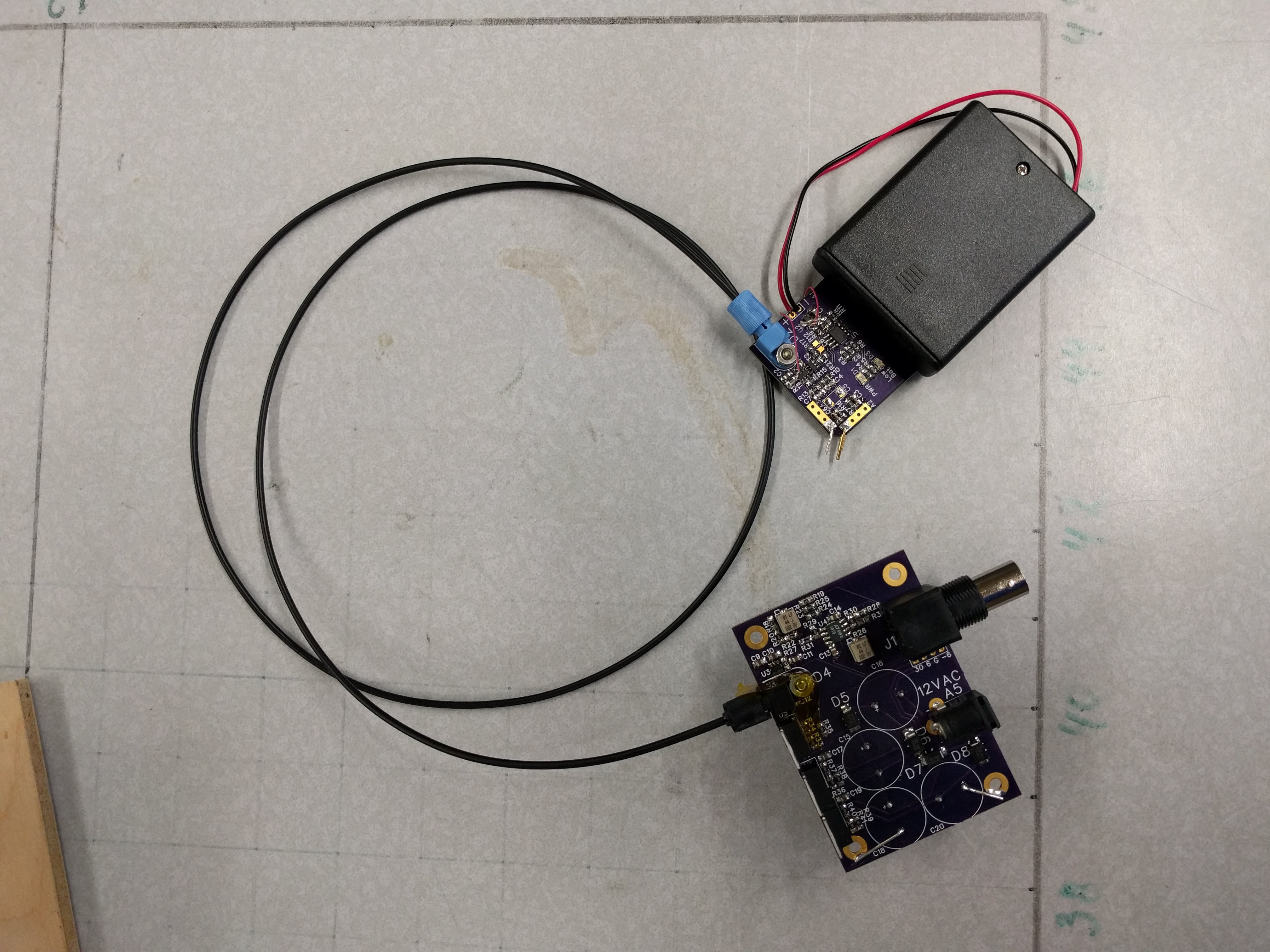
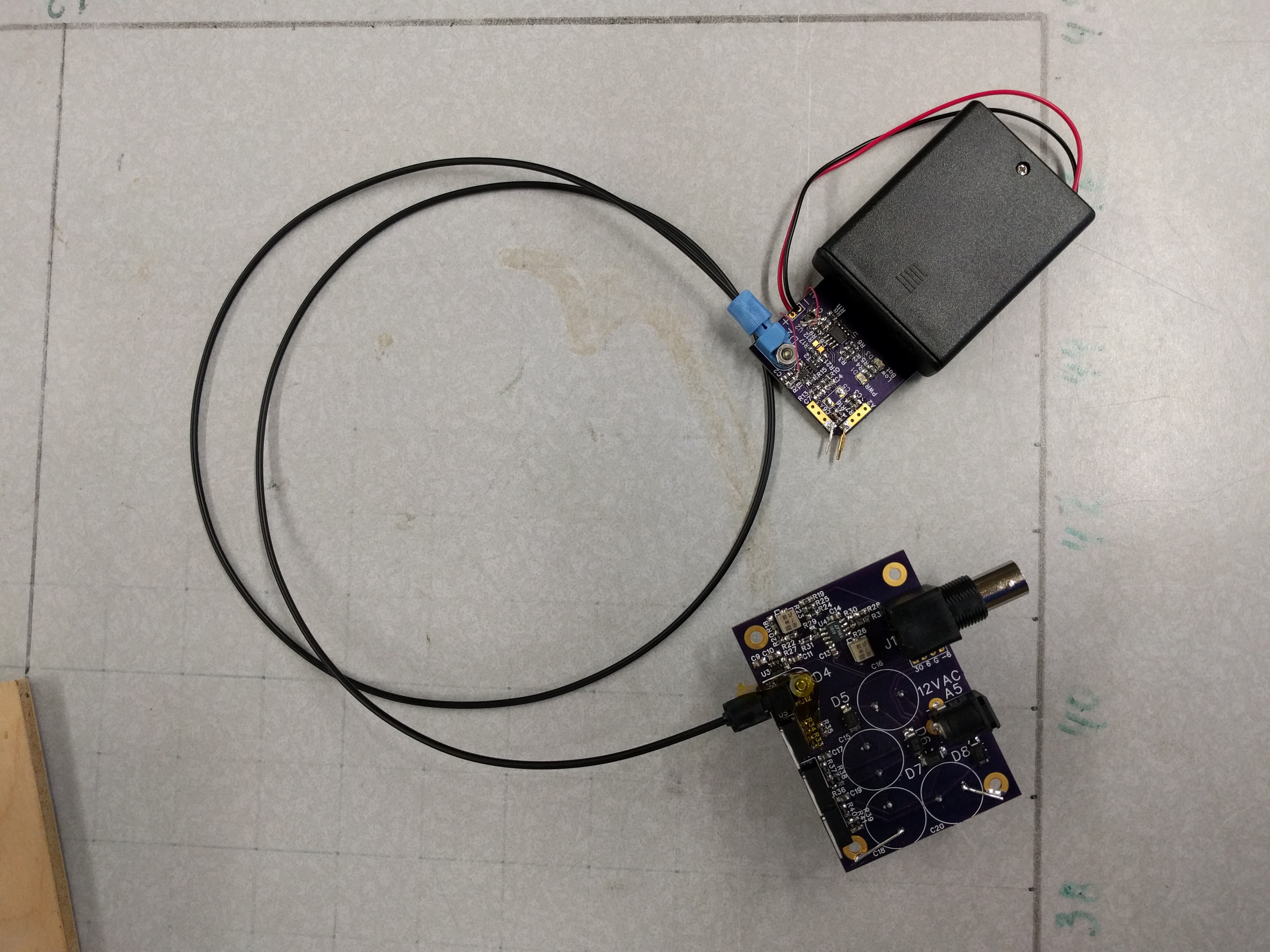
Fiber Optic Isolated Voltage Probe
Use cheap plastic fiber optics to make a useful Isolated Voltage probe for an oscilloscope or other instrument.
Become a Hackaday.io member
Already have an account? Log in.
Just one more thing
To make the experience fit your profile, pick a username and tell us what interests you.
Pick an awesome username
hackaday.io/
Your profile's URL: hackaday.io/username. Max 25 alphanumeric characters.
Pick a few interests
Projects that share your interests
People that share your interests
 Ghani Lawal
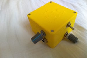
 Pepijn de Vos
 Petteri Aimonen
 Bud Bennett