Close
0%
0%

Monoprice Select Mini Electro-Mechanical Upgrades

Endeavoring to build upon the existing fanbase work of this $200-ish printer.

Similar projects worth following
There is a great following for this printer over social media. I've wanted to get into 3D printing and this is a good start though I wish to address some of this printers deficiencies first.

My approach is from a background of DIY automotive software & hardware tuning, multi-stage electromechanical control system modification, PID control system adjustments, and "hardening" existing hardware for heavier duty work that originally designed for.

If there are adjustments that can and have be made to keep the system functioning under a wider range of conditions, I'm pursuing that. Things like as active cooling, hotend replacement, PID tuning for hotend and bed temperature control, firmware configuration, and frame strengthening/rigidity adjustments are all of interest.

'Knowledge Base'-style document by Ethan Anderson

https://docs.google.com/document/d/1HJaLIcUD4oiIUYu6In7Bxf7WxAOiT3n48RvOe5pvSHk/

Available firmware versions, hosted by Matthew Upp:

https://drive.google.com/open?id=0BxyFI3iDaicLODVZOHI4SzZBNlE

Articles:

Google+ Community:

https://plus.google.com/communities/116802523766279866092/

Facebook Group:

https://www.facebook.com/groups/1717306548519045/

Website Community:

http://mpselectminiusers.com/wp/

MP Select Mini Wiki:

http://mpselectmini.com/doku.php

  • 2 × AOD510 30V N-Channel MOSFET
  • 2 × 1N4448TAP Discrete Semiconductors / Diodes and Rectifiers
  • 1 × EGPD500ELL821MK25H 820 uF, 50V, 135 ˚C, 3.35 A ripple rated. Use this cap to replace teh main power cap on the PCB
  • 3 × EEU-FM1V680H 68 uF 35 V, power rail caps
  • 2 × GRM188R61C475MAAJD 4.7 uF filter capacitor for thermistors

View all 7 components

  • Quick Notes: Extruder resolution vs Z-Axis Resolution

    Michael O'Brien11/03/2016 at 08:42 1 comment

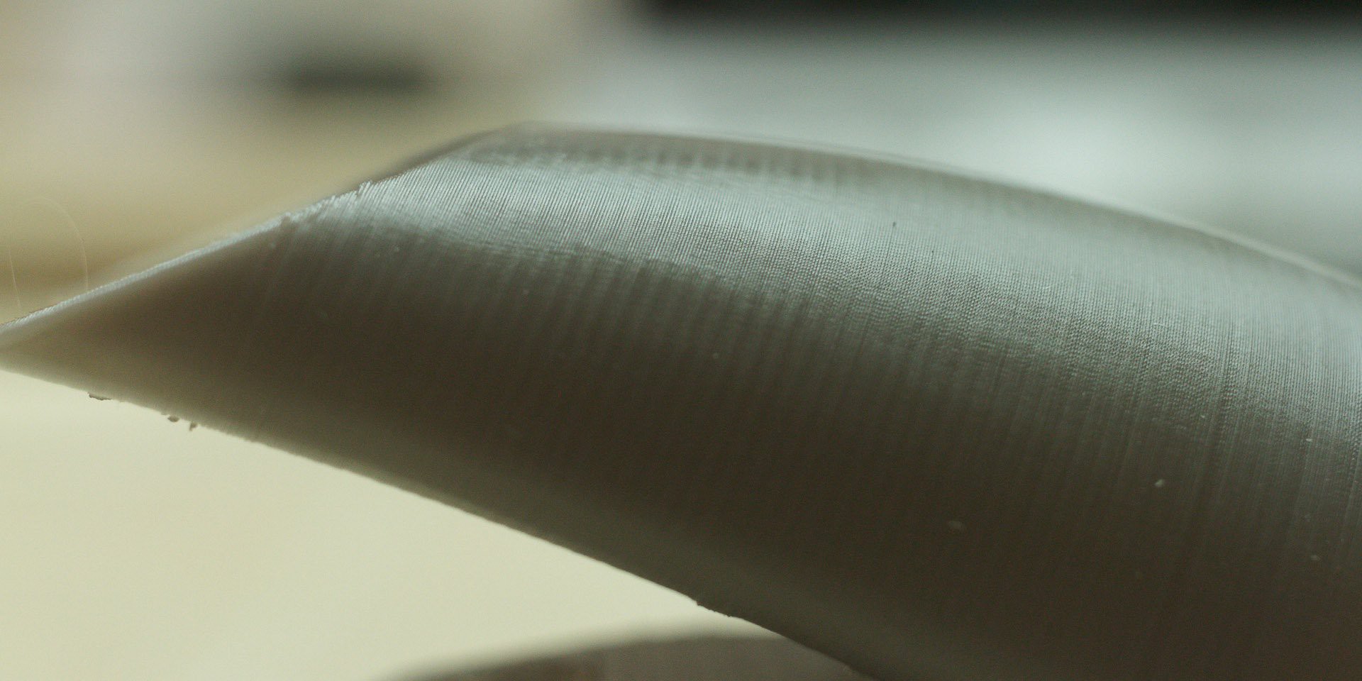
    In one of the photos I posted, I have a ducted fan holder for the E3D V6 hotend. This was printed with a 0.6 mm nozzle and 0.1 mm layer height. If you've seen me on the Facebook group, you know I preach about using 0.04375 mm layer heights and this was before I figured that out. What happens if you increase layer resolution but you do not increase extruder resolution? An explanation after the break.


    If you view the image full res, there is another detail aside from the aliasing banding. If you recall toys of old, and some new, you'll see a pattern on the layers that resembles what fake stitching looks like. Much like fabric threads on those old toys. This is caused by the momentary increase in flow & pressure as the extruder microsteps one tiny bit at a time. Let's quantify that.

    The hobbled bolt has a minimum diameter of ~10.15 mm. This give us a circumference of about 31.8872 mm, aka that amount of travel in 1 revolution. This equates to just over 100 steps/ mm, to which I have my Mini calibrated to 101.6 steps/mm, so all is good. So, in 1 microstep @ 1/16th microstepping of a 200 step motor, how much filament gets pushed out of the nozzle? Almost 85 microns:

    From the resolution shown in the photo, I can say that doubling the frequency of the "stitching" would nearly hide it, but quadrupling it will eliminate it. Thankfully, this driver can easily do 1/64th microstepping if you cut the correct trace. This gives you a length of ~21 microns:

    If we're lowering our layer height to 43.75% of that print, we'll need to double our microstepping to keep a similarly smooth finish. Egads, we're at 1/128th microstepping!

    Now, there is increasing interest over on the FB group for 20 micro layer height. In order to achieve this we need to swap out the drive gear to M5 or M6 rods and due to the slow travel, I'd advise the M6 x 1 mm rod. You should be able to push it at ~4-5 mm/s with 1/2 stepping. Anyhow I digress. If we go from a 43.75 micron height to 20 micron height, we have the same type decrease again. If we're going this small, then it's likely that we'll be using fine nozzles too, such as 0.25 mm. We'll probably want a 0.9˚ stepper too.


    Granted, all of this is theoretical and doesn't account for post-processing such as flame brushing, acetone, or the like to clean up the surface. However, the finer you start with, the finer you finish with. If you do not tend to the extruder when you thin the layers, you're not gaining as much as you could.

  • Axis Resolution & Speed

    Michael O'Brien10/09/2016 at 14:24 0 comments

    I've mentioned before that the fastest I've measured from this board's microcontroller is ~38 kHz. With some math which I'll show later, this gives a theoretical speed of ~395 mm/s for the X, Y, and Z-axis steppers. However, stepper driver speed and torque is a much more complex issue than I even expected. Here is what I've learned so far and I want your help to point me which direction I should go.

    PS: This is a *long* post

    Read more »

  • Supporting X-Axis Expansion

    Michael O'Brien09/22/2016 at 11:41 0 comments

    Balance. Why is it needed? One end of the X-axis is unsupported. If you extend this out, there should be enough force to have thins begin to bend. I'm not an mechanical engineer so I cannot calculate how much the 3 Z-Axis rods will bend when you're mid way up the Z-height, and you're X is at 120-125 mm, but I cal calculate the torque with reasonable precision. If you're going to extend this axis, you need to worry about it a bit.

    Read more »

  • X, Y, Z, A Motors & Stepper Driver Investigation

    Michael O'Brien08/29/2016 at 00:56 0 comments

    This is really a "Part 3" to the other two, but it doesn't have much to do with the modifications of the axis. This here is just a place to details the motors list, technically 3 types, and their specs in case someone wants to upgrade them. I'm also fairly confident that I've identified the Z-axis motor.

    Read more »

  • X, Y, Z Axis details - Part 2

    Michael O'Brien08/27/2016 at 00:59 4 comments

    Note 1: I capitalize "X-axis", "Z-height" and the like for legibility when scanning/skimming; pedants can hate me later.

    Note 2: This is where idealistic, that is mimal change for best outcome, modifications are. For measurements and construction details of the mechanical structure see Part 1.

    Disclaimer: Due mostly to human error but some manufacturing tolerances, the following apply.

    • Diameters/measurements under 50 mm have a +/-0.05 mm tolerance
    • Lengths over 100 mm have a +/- 0.5 mm tolerance

    Let's get crackin'! the simplest two axis to modify are the X-axis and then the Z-axis. Before we start, keep in mind that increasing the travel distance of any axis creates the ability to have the current wiring suddenly become too short. Effectively, you're going to have to re-work a good portion of the machine in order to have these modification 100% usable.

    Either way, it is possible to stiffen the Z-axis a bit by boring out the carrier's rear bearing mount, the two mounts for the shaft, and dropping in an 8 mm shaft. Though the most flexion will take place on the front two shafts, the rear shaft can be upgraded to an 8 mm shaft and linear bearing to aid in rigidity.

    Z-Axis

    The graphite injection molded Z-axis-bearing-and-A-axis-NEMA-17-holder is 45 mm tall. It has the sheet steel cover that is a hair over 58 mm tall that bolts to it. If you remove this, you technically gain 17 mm of z-height travel. At this point, there is 25 mm of threaded rod left before you hit the coupler. Cut, file, or grind off another 8-9 mm of the back chassis's frame, re-position the z-height limit switch by 1" or ~25 mm, put a 1" spacer under the tower, and you just increased vertical build height by ~20%. In you want more and have a greater mechanical inclination, you can buy replacement Z linear rods and a threaded rod for the Z-axis drive for less than $25.

    X-Axis

    The X-axis is a different story. Both X-axis rods are friction fit into the graphite composite pieces and have a little bit of glue/sleeve lock/retention on two ends. With the help of some elbow grease and vice grips, I can matter-of-factly tell you you that the rods are 209 mm and 287 mm long. The top rod slides through 2 holes thus provides alignment for the bottom one to a degree. Their total is just under a 500 mm stock length.

    McMaster's next size is 2x the length, 1.2 meters and though it's expensive compared to the printer at ~$32, it's not that bad. Now and 8 mm rod will be stiffer, but also heavier and the Z-axis carrier doesn't have enough meat to bore out the holes. Given the machine we have, I'd say that if you want to expand the X-axis too much beyond 200 mm, you'll need the rigidity of 8 mm rods for this gantry. The added weight will then necessitate at least 1 of the 3 Z-axis rods being switched out to 8 mm as well to counter the flexion.

    Z-axis Carrier

    There is one problem though. The X-axis carrier is only 17 mm OD for the bearing retention portions of the composite. On the Z-axis composite, the front two are ~17-17.75 mm OD, but the rear is 20 mm OD. You'd get a 1-1.375 mm wall on the front two if you wanted to put an LM8UU/LM8LUU in there but the rear bearing retention portion would give you about a 2.5 mm wall. BUT, the rear Z-axis linear bearing mounts are 11 mm thick, not 9 mm and the rear A-axis bearing retention portion of the composite is 20 mm. In other words, swapping out and drilling out the single Z-axis linear rod from 6 mm to 8 mm is feasible without facing integrity.

    Belts

    As soon as you start talking the extension of the X-axis or Y-axis though, you have to address the drive problem; the timing belts. I'm going to default to McMaster again on this. It appears that "MXL" is a designation for miniature extra light which is a designation for tooth pitch and that the number is supposed to reflect the number of teeth thus 236MXL means 236 teeth at 0.08" tooth spacing. McMaster's neoprene belts have more teeth that this, but their urethane belts are just fine. So as such the 235MXL...

    Read more »

  • X, Y, Z Axis details - Part 1

    Michael O'Brien08/26/2016 at 02:51 0 comments

    Note 1: I capitalize "X-axis", "Z-height" and the like for legibility when scanning/skimming; pedants can hate me later.

    Note 2: This is part one where measurements and construction details of the mechanical structure are listed. Idealistic modifications are in Part 2.

    Disclaimer: Due to human error but mostly manufacturing tolerances, the following apply.

    • Diameters/measurements under 50 mm have a +/-0.05 mm tolerance
    • Lengths over 100 mm have a +/- 1 mm tolerance


    Hey, the title for the project is 'Electro-mechnical' so it's about time I make good on the latter half, no? Before anything can be modded, we need to have a close look at what the mechanical structure is and then adjustments can be made from there.

    Read more »

  • Control Board MOSFETs

    Michael O'Brien08/16/2016 at 22:17 0 comments

    I've had a chance to go over datasheets with Engauge Digitizer for over a dozen MOSFETs. Here is a quick top 5 list of best picks if you wish to switch yours out. Keep in mind, @ 147.5 Hz, switching losses aren't that high so Rds(os) dominates. This means that the stock MOSFETs dissipate ~0.75 W on full duty cycle.

    Stock - AOD484

    • Vds: 30V
    • Rds(on) @ 3.2V: 74 mOhm
    • Gate Charge @ 4.5V: 8.4 nC
    • Ciss: 938 pF
    • Coss: 142 pF

    Read more »

  • Quick-n-Dirty Stock PSU Notes

    Michael O'Brien08/15/2016 at 11:51 3 comments

    The Big Ass Cap for input filtering is a Nippon Chemi-Con 400V 220 uF snap in cap. I wouldn't bother with pricing out a replacement...

    Read more »

  • Final PID Notes on Stock Setup

    Michael O'Brien08/11/2016 at 10:13 0 comments

    So, this is PID but not PID. It's the Shakespeare of PID. I don't really care if I'm being dramatic because the stock setup is weird. Yes, I'm new to 3D printing and though this hotend may be the 8th incarnation, but man, it really could be better.

    Read more »

  • 24V will work, technically

    Michael O'Brien08/05/2016 at 03:17 2 comments

    I've mentioned this before and before I get into other stuff right now, I'll say it again: you can drive this board from a 24 VDC power source. Just because you can though, doesn't mean you should.

    Read more »

View all 22 project logs

  • 1
    Step 1

    Adjust hotend with preliminary PID to the following for greater stability:

    Record down the stock PID values, or whichever custom ones you have used previously. To display them enter in

    M501
    

    Enter in new PID values. Both 'C' & 'L' are reset and rate variables. (I advised the 1st set)

    M301 P36 I0.01 D72 C0.12 L2
    
    or
    M301 P80 I0.01 D80 C0.25 L2
    

    And update the heated bed's PID values:

    M304 P106.56 I0.024 D96.81

    Save and display currently saved config

    M500
    M501
    

View all instructions

Enjoy this project?

Share

Discussions

Ray Hayes wrote 03/07/2017 at 22:57 point

your equations need some work. The 1st term should be Pi*10.15 (circumference) rather than Pi*(10.15/2)^2 (cross sec area). The left side um values are correct but might be good to convert to volume )(cu mm) then to the width of the trace for a given layer thickness considering print speed.  

  Are you sure? yes | no

Michael O'Brien wrote 06/21/2017 at 05:00 point

Thank you for that catch.

I'm currently busy with home redecorating and consolidation with the arrival of new furniture. I'll fix it as soon as possible.

  Are you sure? yes | no

anthony.sleck wrote 12/23/2016 at 14:42 point

Michael O'Brien ... I have to comment. Good Work. I used your PID settings and have way better results in temperature stability...

  Are you sure? yes | no

Andrew Dupont wrote 12/05/2016 at 21:07 point

Thanks for doing this! I'll be following along. One question: I've seen it suggested a couple times that the noisy 30mm fan on the hotend is the result of a coarse PWM signal that could be smoothed out a bit with a 0.1µF capacitor between the fan's power and ground wires. Seems like a simple enough fix, but I don't know enough about EE to know the risks and drawbacks. Maybe it's worth visiting in a future entry?

  Are you sure? yes | no

Michael O'Brien wrote 12/23/2016 at 04:03 point

I have a replacement board with proper PWM working on it. I'll look into it when I get there.

  Are you sure? yes | no

mac_ha wrote 12/02/2016 at 11:04 point

A lot of useful information, still trying to digest!.. However, could you check the links for the photos on your second Logs page - none of them are visible! Thanks in advance!

  Are you sure? yes | no

Michael O'Brien wrote 12/02/2016 at 19:05 point

a lot of the photos I host locally on a file server of mine which is down due to home repairs. They'll be back up later

  Are you sure? yes | no

Alan Rager wrote 11/08/2016 at 21:00 point

I blew up the traces for the hotend mosfet and don't know where else to connect the gate. Do you have any advice on where I can try to fly some wire to connect it instead?

  Are you sure? yes | no

Michael O'Brien wrote 11/09/2016 at 01:19 point

Please see the PM I sent you

  Are you sure? yes | no

Similar Projects

Does this project spark your interest?

Become a member to follow this project and never miss any updates