Below are some images of the reflow process. White PCB scraps were used around the edges of the board. This keeps the stencil from bending over the edges of the board that will be reflowed. Blue painters tape was used to hold down the white PCB scraps and the left edge of the stencil.
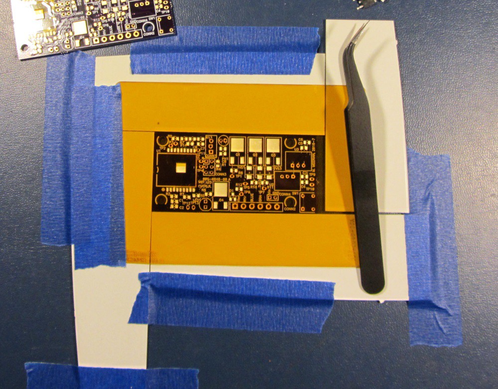
Figure 1: Board A ready to have solder paste spread
The paste was spread on all boards. It looks like the stencil was a little low on the board near the top. (the D-pak heatsink tab is missing some paste)
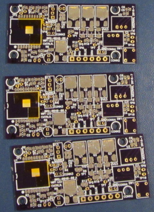
Figure 2: The paste is down on all 3 PCB's
I use a $20 walmart hot plate for reflowing the SMT parts. I've been using it for years without trouble. I turn it on and it takes about 3 and a half minutes to reflow the PCB's. (An old school stop watch was used, near the top of the image) The boards are lifted off of the hot plate by tweezers.
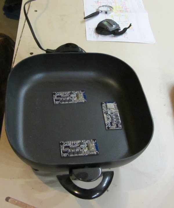
Figure 3: The PCB's ready for reflow on the hot plate
The board reflow process seemed to turn out good. I did not see any tombstoned parts or any solder bridges. I think the stencil really helped with this. Usually, if I put down paste by hand I get many solder bridges.
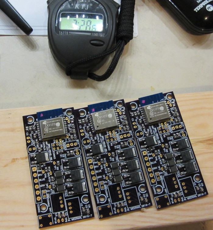
Figure 4: Reflowed boards!
The next step is to install the through hole parts and then start on the electrical testing. Hmm. I should also post some details about the software.
Discussions
Become a Hackaday.io Member
Create an account to leave a comment. Already have an account? Log In.