 Ted Yapo
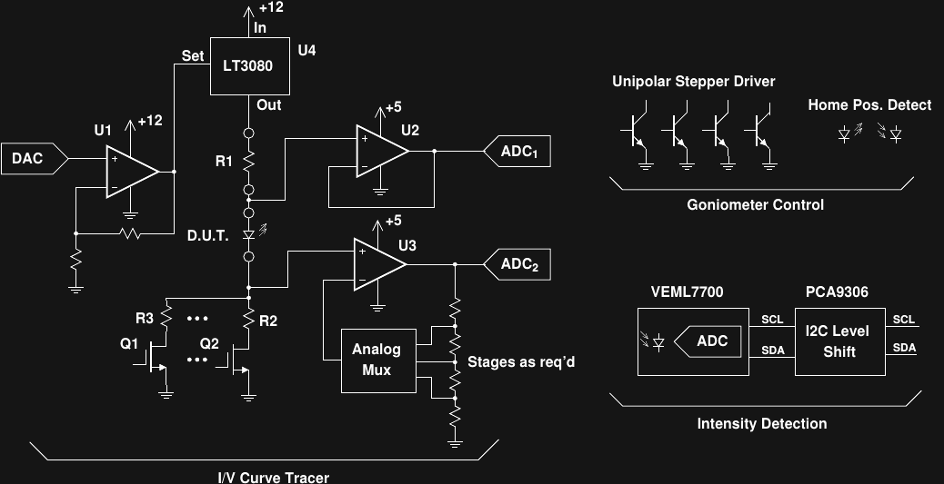
Here's a digram of the more detailed system-level design. This isn't intended to be a complete schematic; small details have been omitted.
Electrical Subsystem
I've chosen to use a PIC16F1778 microcontroller for this project (not shown). The '1778 has 10-bit ADC and DAC capabilities and on-chip voltage references. Communication with a controlling PC will be over a serial connection using a USB/UART bridge. Data analysis and plotting functions will be programmed in python on the PC side.
The electrical measurement system is driven with a pseudo current source consisting of U4 and R1. U4, an LT3080 variable regulator, serves as a current-limited and thermally-protected variable voltage source driven by the PICs DAC. U1 provides some gain to boost the range of the DAC output. R1 is selected by the user in accordance with the expected current range: since no measurements include R1, no special tolerance parts are required.
A set of switchable current-sense resistors (R2, R3, and possibly others) are selected with ultra-low-Rds MOSFETS driven from PIC output pins. The wide current range (100uA to 1A full scale) necessitates using a selectable set of sense resistors to maintain accuracy. The voltage drop across the resistor(s) is detected with U3, an inexpensive auto-zero op-amp. The gain of U3 is selected using an analog multiplexer and a resistive divider chain. A 10-bit ADC on the PIC captures the current measurement.
The voltage drop across the DUT is buffered by U2 and read by a second PIC ADC channel.
Optical Subsystem
In the past, I've designed optical sensors like the one required here with photodiodes and transimpedance amplifiers made with precision op-amps (including one design just a few months ago). This time, I'm going to try something different. Perusing the DigiKey catalog, I found the VEML7700 Ambient Light Sensor made by Vishay. This is a new part (2016) which doesn't seem to have gained much traction in the hacker/maker community yet, but I'm guessing it won't be too long before it does. The device is aimed at ambient light sensing for automatic brightness controls on televisions and similar appliances, but the specs are excellent for my application as well. The sensor measures light levels from 0 lx to 167 klx with 0.0036 lx resolution. For reference, Wikipedia lists the illuminance from the full moon as 0.27-1.0 lx and direct sunlight from 32-100 klx. The part contains an integrated 16-bit ADC, and reads data out over I2C. All this for $1.94 (single-quantity pricing). It actually contains two sensors - one closely matched to the human eye response (photopic vision), and one with a broader (white) spectral response. Ratios of the two responses may provide some small measure of emitted spectra.
Angular Subsystem
To measure the angular output distribution from the DUT, I intend to rotate it through a series of angles using an inexpensive 28BYJ-48 geared stepper motor. At each angular position the intensity will be recorded by the fixed position sensor. Since the gear train on these steppers is plagued with backlash, the motor will be driven in one direction only, and "home" position will be detected by a simple optical sensor. I envision a simple screw-terminal mount for through-hole LEDs and laser diodes, and a set of carrier boards for common SMD LED packages to attach the DUT to the motor shaft. Being a unipolar stepper motor, the 28BYJ-48 can be driven with four NPN transistors controlled by PIC output pins.
Next Up
I've ugly-prototyped a light sensor with the VEML7700, designed a PCB (now in fab), and written an arduino-compatible library for testing it.
Discussions
Become a Hackaday.io Member
Create an account to leave a comment. Already have an account? Log In.
I can't say I like the part with R2/Q2 and R3/Q1. Rdson will be added to resistance of sense resistors, creating additive voltage drop. What is worse, Rdson (and the voltage drop) depends more-less on the drain current, making the resistance somehow non-linear and dependant on temperature. Depending on ratio of value of R2 and R3 and Rdson of transistors, this non-linearity may induce measurement error.
Depending on needed accuracy, you may want to use differential amplifier just before U3 and switch its low input via multiplexer to the cold end of R3 or R2 (depending on which transistor is switched), sensing the "pure" voltage drop on sensing resistors, minus the voltage drop on transistors. Instead of diff amp, another amp and mux to switch amplification factor, you may take advantage of ready-to-go PGA, like MCP6S21, for example.
I employed similar trick (though using high-side switch instead of low-side on your project) in my project #Micro progmeter see here in schematics https://github.com/jaromir-sukuba/micro_progmeter/blob/master/hw/6e.sch.pdf components R6, R7 and NC7SB3157 MUX switching input into negative input of differential input ADS1120 to achieve resistance measurement among 4-5 orders of magnitude (even complicated by the fact I have non-switchable voltage divider at input).
Are you sure? yes | no
Yeah, I didn't like the MOSFET switches as part of the shunt resistor at first, either. Then I started working up an error budget and figured that with a 1.4 milliohm Rds (max) I could afford to switch a 1-ohm sense resistor on the 1A range - this only adds 0.14% error. That might double over temperature (Fig. 13 datasheet below), but I'm not going to use it at 180C. I ordered a few of these for the prototype (they're not here yet):
http://www.nxp.com/documents/data_sheet/PSMN1R0-30YLC.pdf
I know it sounds like a waste to switch the 1A current shunt with a 100A power MOSFET, but they only cost $1, which is less than a decent instrumentation amplifier. I haven't tested it yet, but I have tested a STP27N3LH5 (20 milliohm Rds) that I had on hand, and measured a consistent 30.3 milliohms (including some long leads and connectors before the Kelvin connection points) from single mA to A current levels.
For lower-current ranges (and larger sense resistors), I can use lower-spec (cheaper) MOSFETS and maintain the same accuracy.
The larger problem may turn out to be the Idss leakage current from the "off" MOSFETs. It's specified for 30V Vds (and too large at extreme temperature there), but not for lower voltages (like 1V max that I expect).
You're right, of course, in that I could use an instrumentation amp switched just across the selected shunt instead. It's a good idea, and I'll give it some thought. I'm also having a look at #Micro progmeter - nice!
Are you sure? yes | no
Yes, it all boils down to ratio of sense resistor to Rdson, considering the needed accuracy. For 1A I expected sense resistor somewhere in 100nOhm-1Ohm range, that's why I worried about it.
The Idss leakage is usually higher on power transistors, so you probably need to make compromise between leakage (high power transistors) and voltage drop (low power transistor).
By the way this is circuit where old fashioned relays could work just fine.
Are you sure? yes | no