 Pamungkas Sumasta


This Project...
is not just about making another DIY-keyboard, but it's all about creating a smart-connected device. A device which 'talks' to your surrounding, able to make its own decision and aim primarily to assist you in interacting with digital world by introducing some sort-of an automation and flexibility. Of course, while retaining its functionality as your casual keyboard in most cases.
is not just about helping or assisting, but shaping the way you interact with the digital domain in a long term. Self-deactivation after hours in front of computer or automatically kill your browser in case you've been in social media for too long are just an example of how it can help shaping the better you. Not to mention about several other neat feature such as securely embedding your passwords within the keyboard itself.
is not just about another keyboard that does Macro, but instead, it's all about a keyboard that generates its own macro depending on your surrounding and just the way you want it.
is not just about a bunch of switches where it does the exact same thing every single time, but it's all about dynamic community driven features.
is not just about a device that waits for your command, but it's all about having a two-way typing companion.
And lastly, it is not just about a keyboard.

"What I'm about to tell you is top secret. A conspiracy bigger than all of us. There's a powerful group of people out there that are secretly running the world. I'm talking about the guys no one knows about, the ones that are invisible. The top 1% of the top 1%, the guys that play God without permission." -Elliot, Mr.Robot.
Specs:
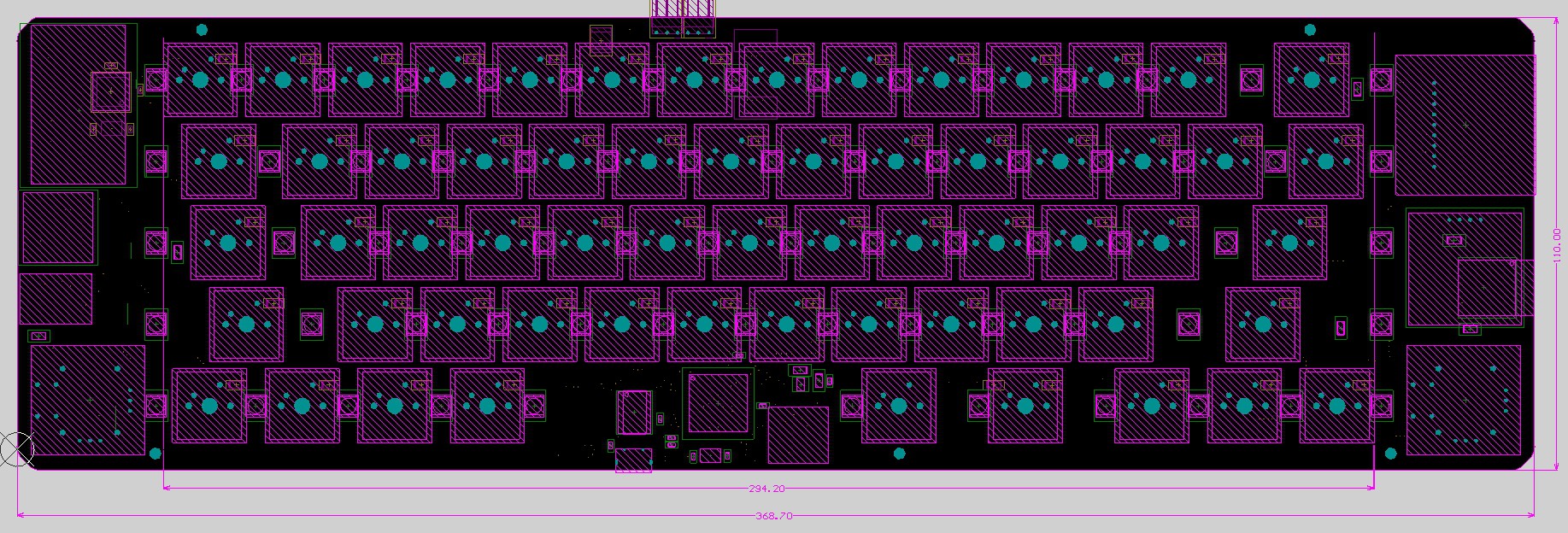
- True wireless keyboard
- No wires allowed. Communication and charging everything is done wirelessly.
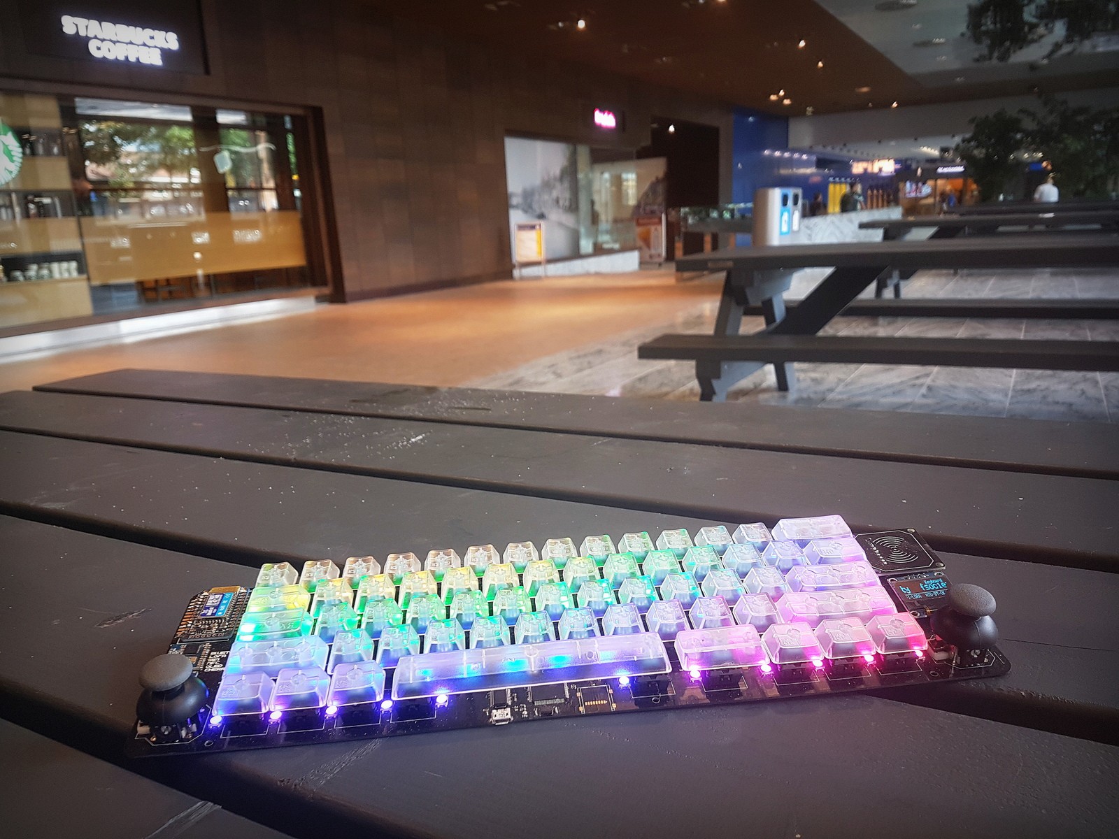
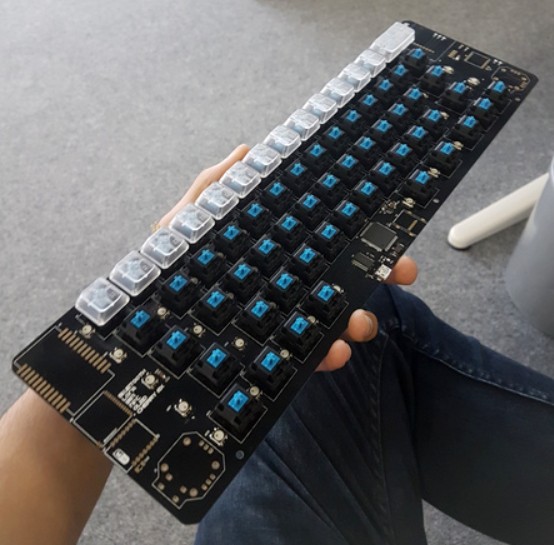
- Fully Portable
- Due to the wire-free policy, making it portable is as easy as it sounds.
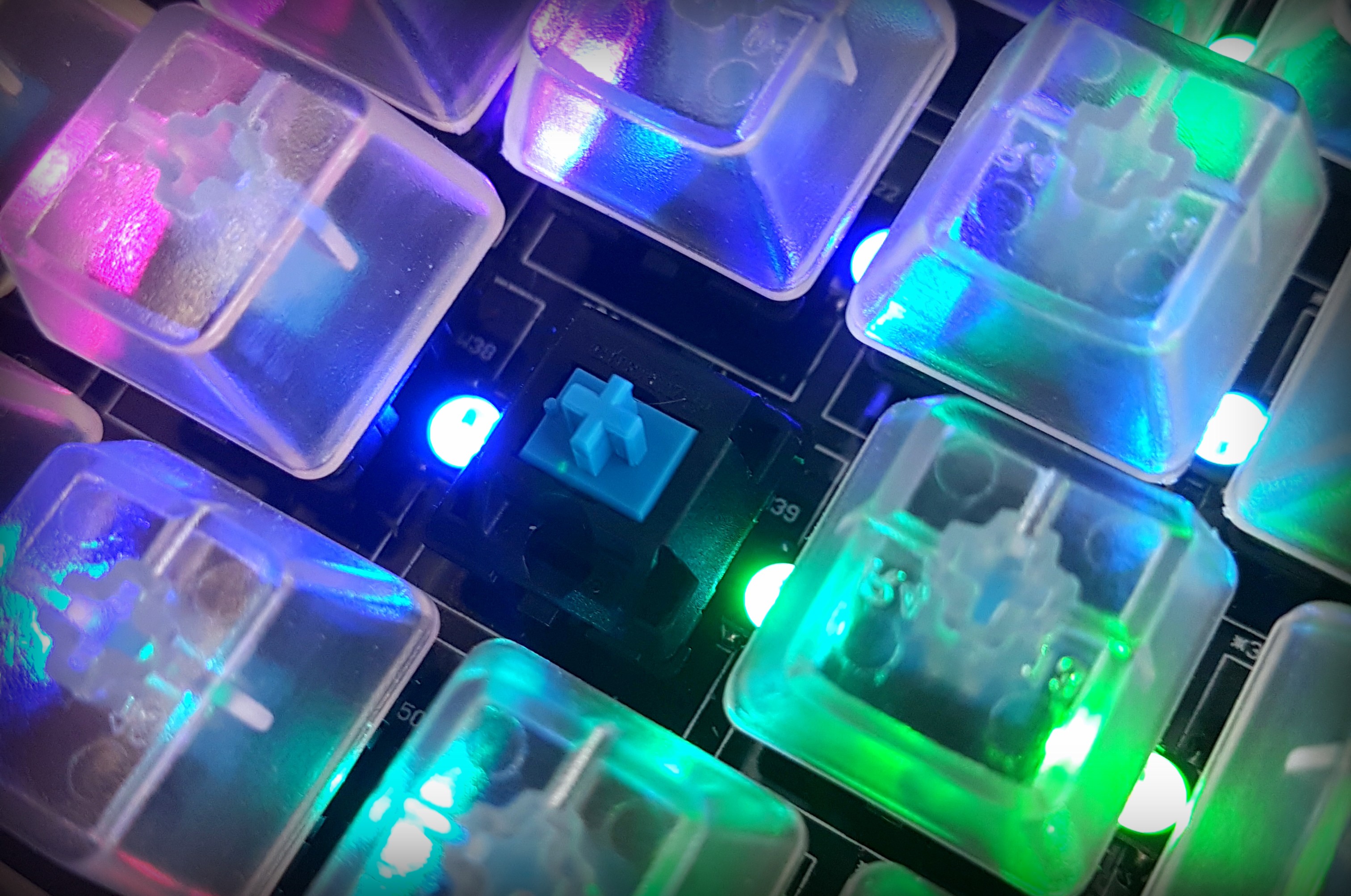
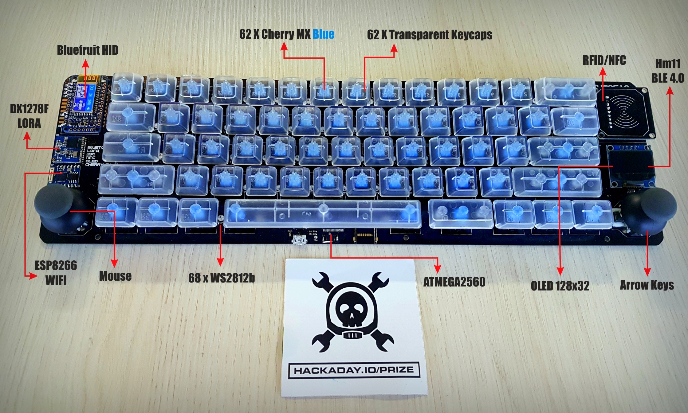
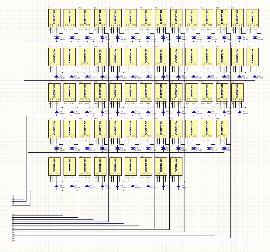
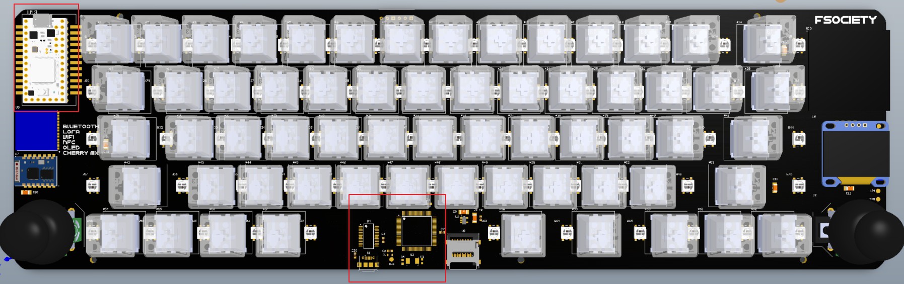
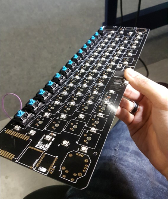
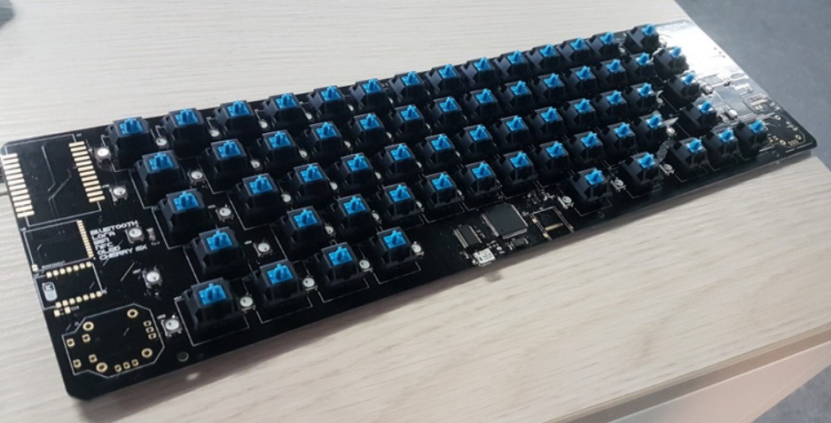
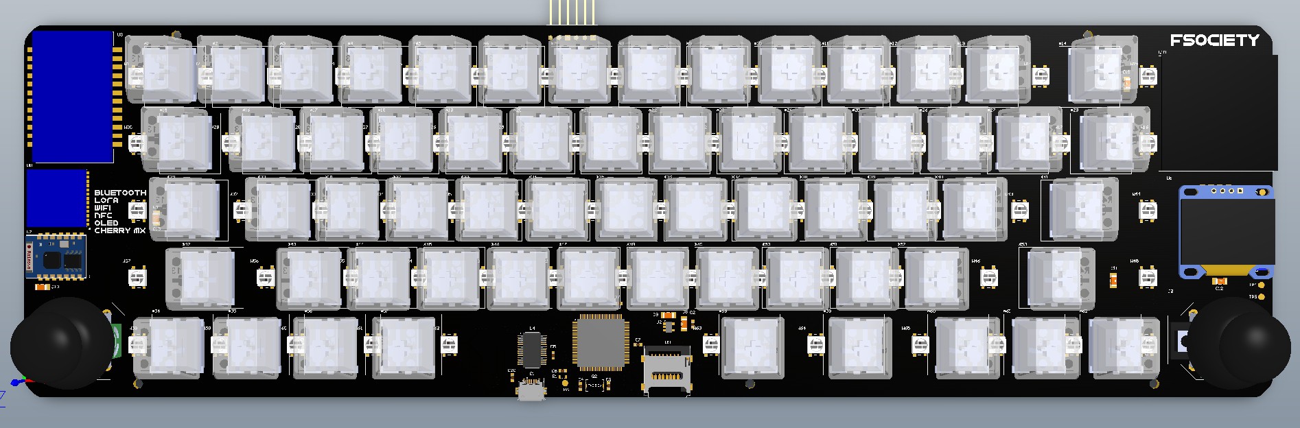
- 62 X Cherry MX mechanical switches
- Yes, no discussion about this. Cherry MX or no keyboard at all. Did I say it has to be Cherry MX Blue as well?
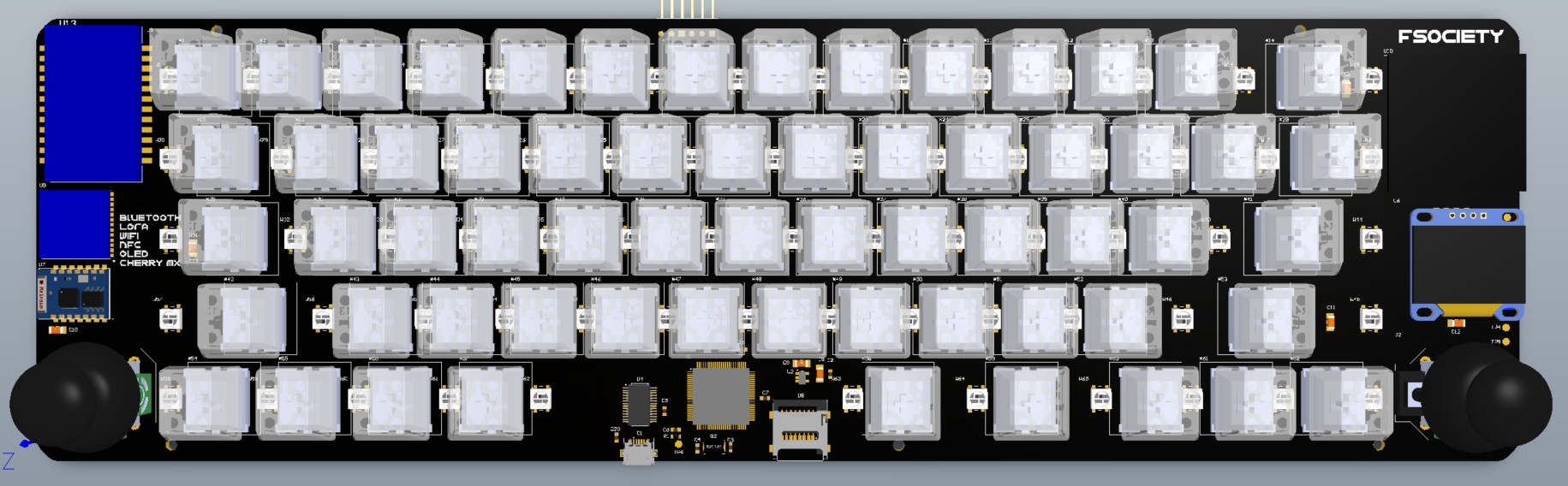
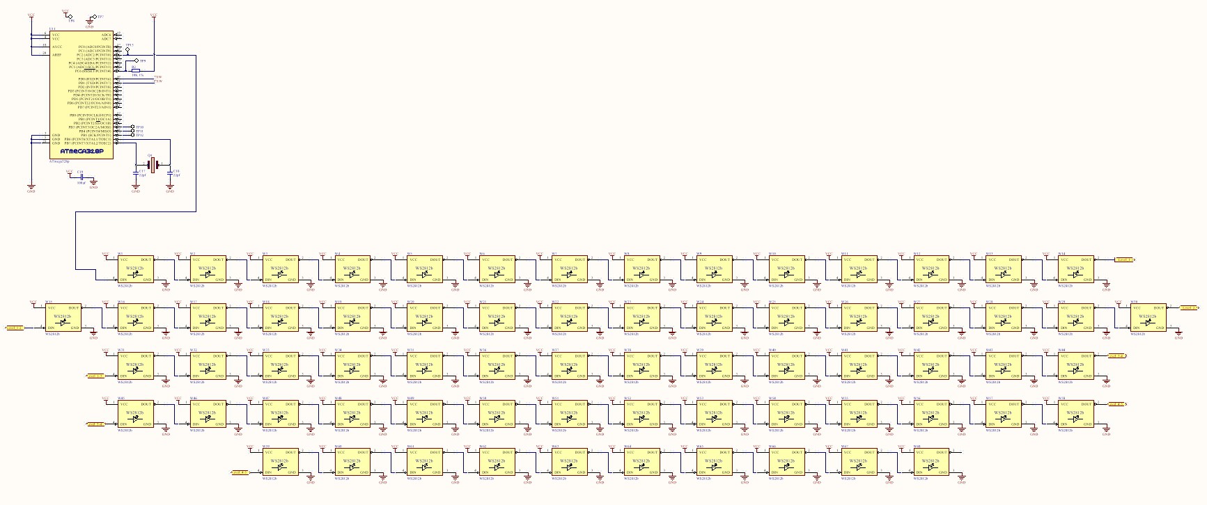
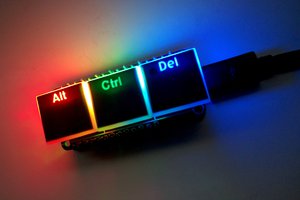
- 68 X RGB LED backlight
- An array of WS2812b black version embedded on the board. Who could've thought maker's favorite RGB led is underneath a keyboard.
- 2 X Thumb Analog Joystick
- On the left side simulates the mouse movement while the right side trigger the arrow keys.
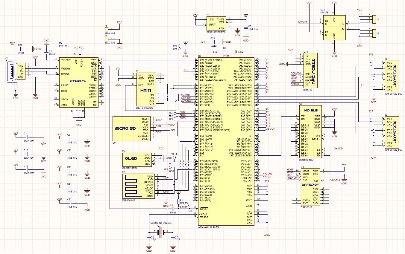
- Security (RFID/NFC)
- In complement with things like NFC Ring, or smartphones NFC, having a secure on-board password activator doesn't sound impossible.
- Internet of thing thingy
- To enable independent internet access, ESP8266 Wifi dongle was added on-board.
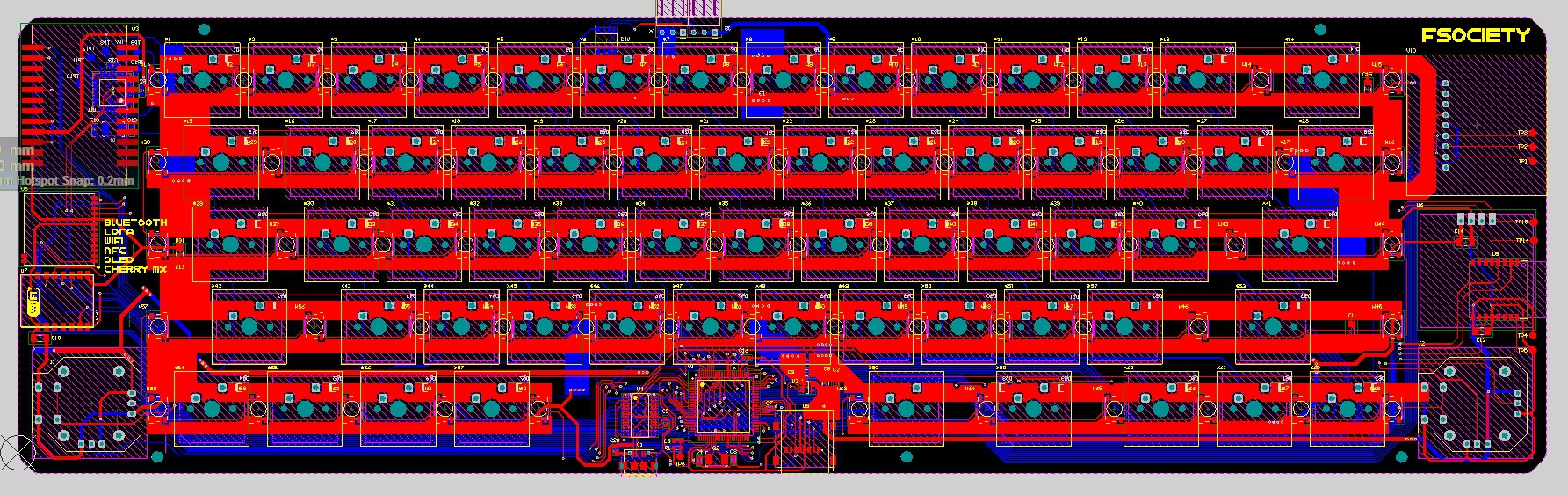
- Local wireless communication (Bluetooth 4.0 & LORA)
- Talks wireless-ly with local networks that you've setup is now possible with Bluetooth and growingly popular LORA network on-the-go.
- Bluetooth HID
- Bluefruit HID link from adafruit is used to enable pure wireless system. This significantly save development time.
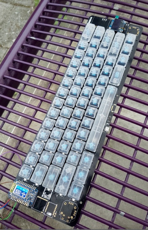
- OLED Display
- 128x32 pixel OLED display embedded for some indications and notifications on board.
- Local Storage
- Micro SD card should be able to handle the demand in here.
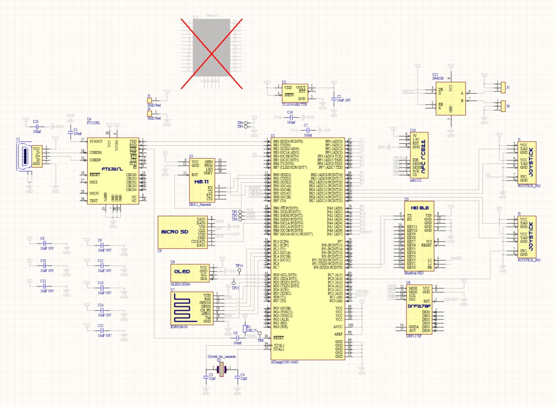
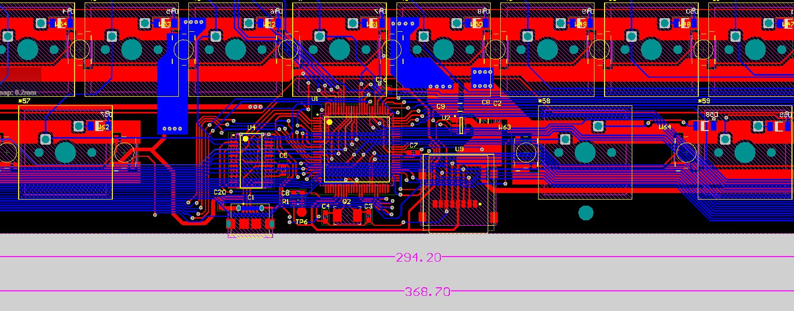
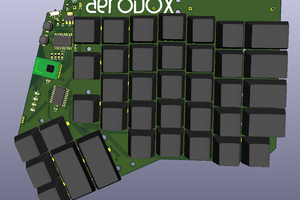
- Microcontroller
- For the first iteration, old School ATMEGA2560 is used. Together with atmega328p a co-controller for the WS2812b LED.
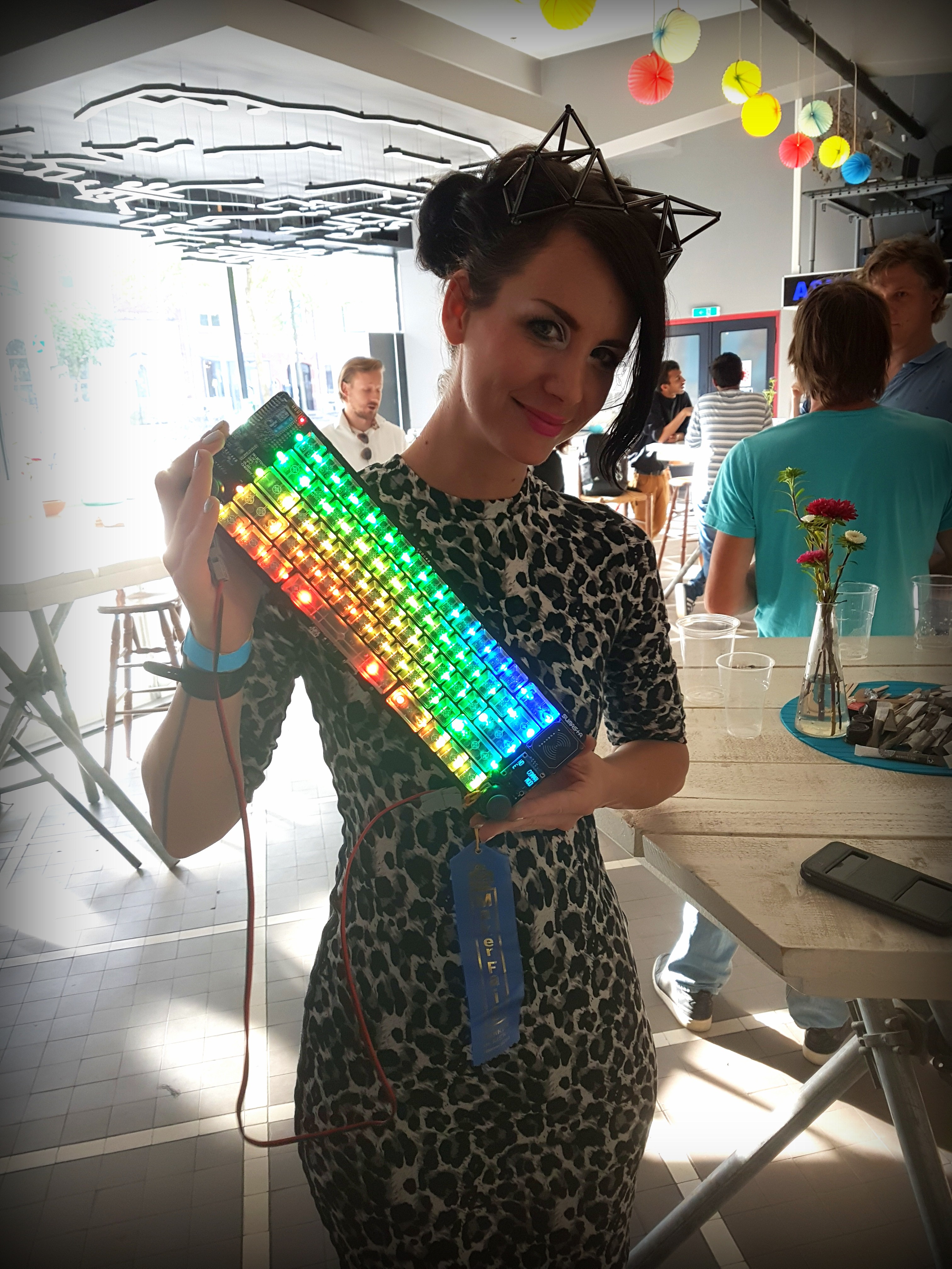
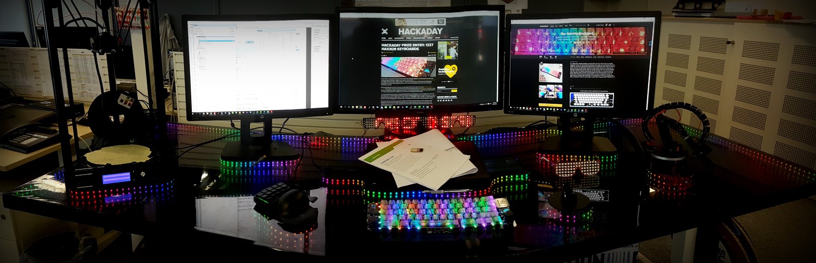
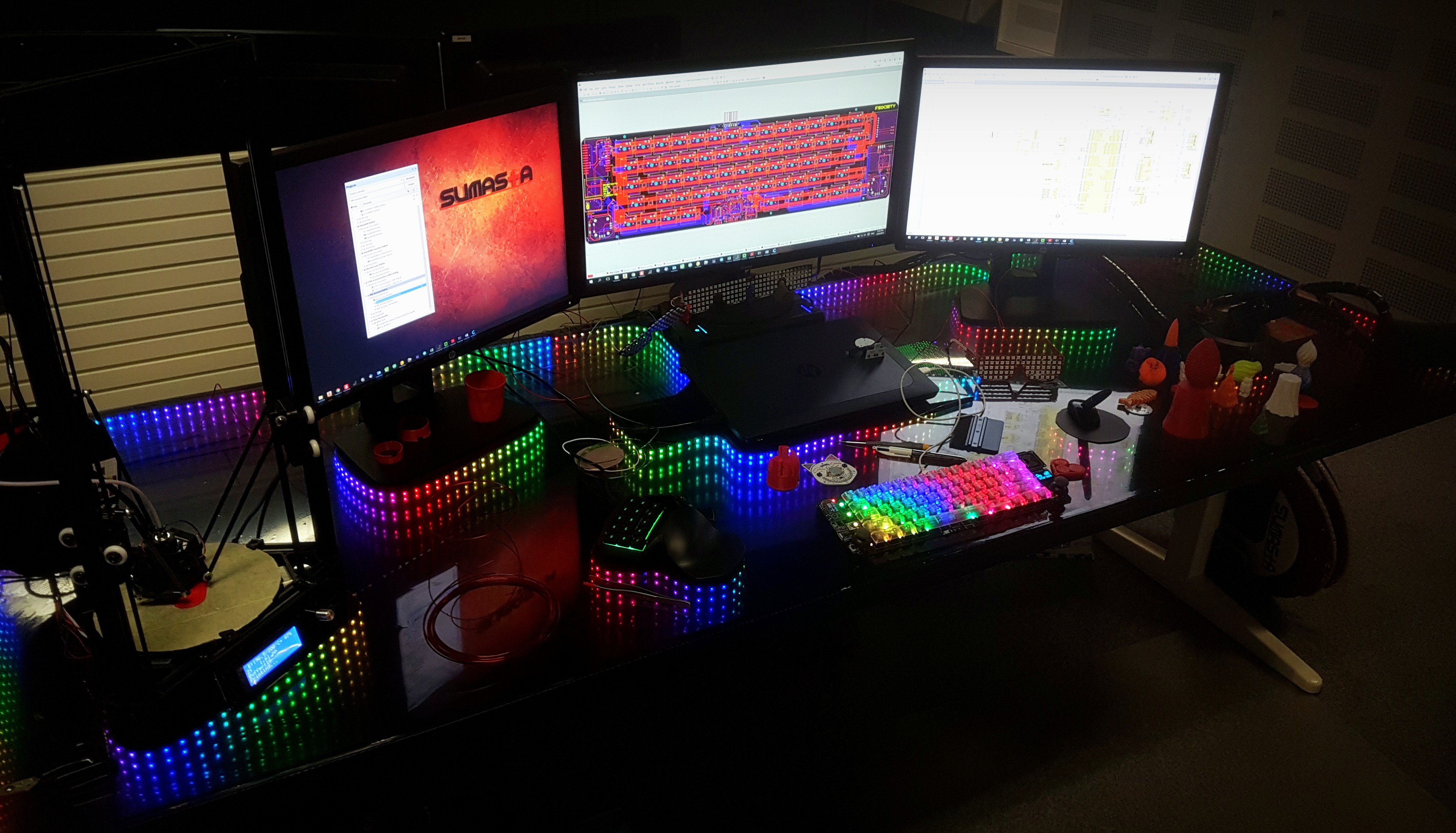
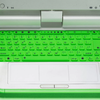
Fits on all circumstances. Either chilling-out:
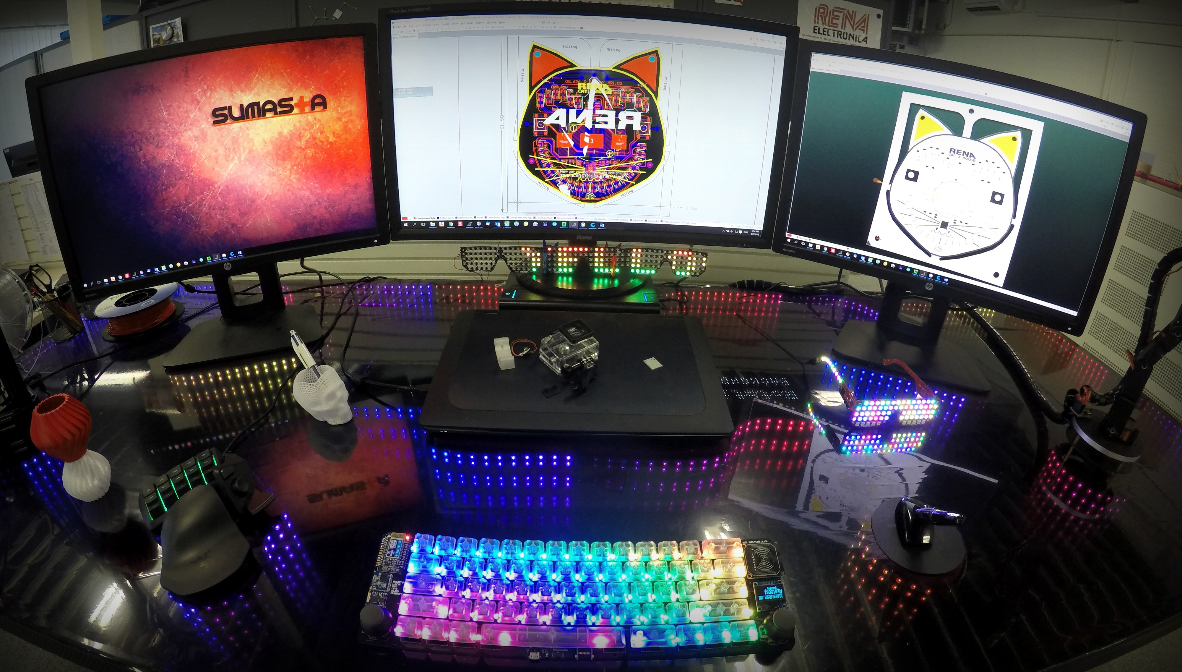
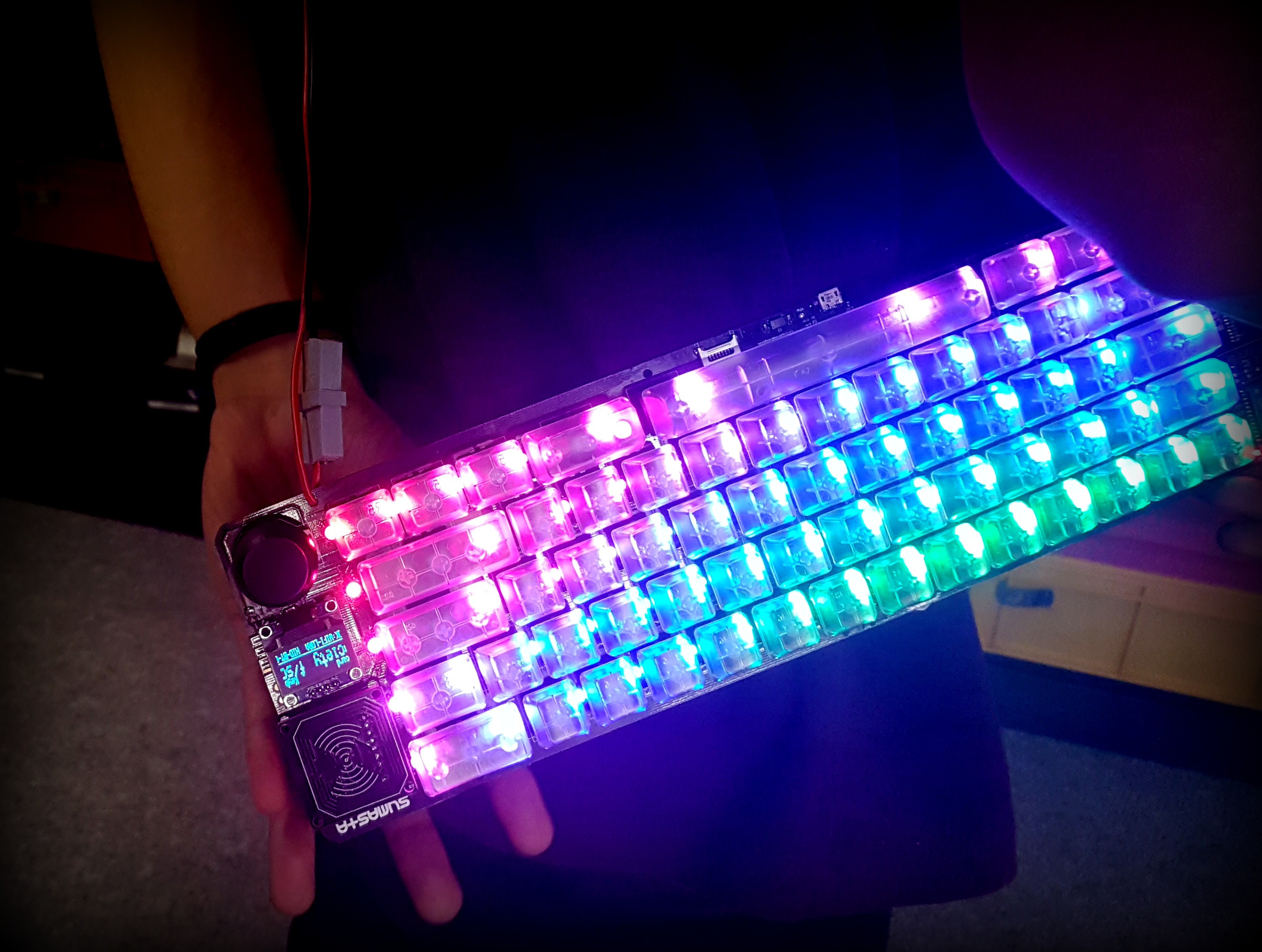
Or on a Heavy-Duty working environment:


 deʃhipu
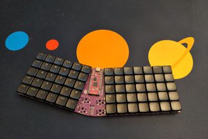
 Simon Merrett
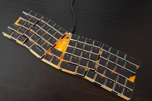
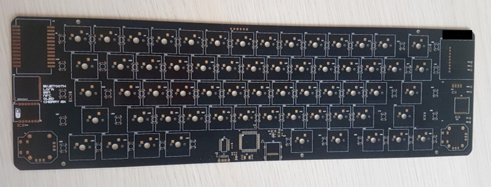
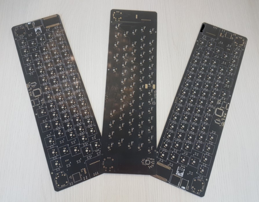
Good news! I submitted the zip file to PCBWAY and then created boards and now I have them in hand. Bad news is that several of the chips are not available. And real bad news in looking at the soldering required for Atmega2560. Youtube show techniques for micro-processor soldering. My next step is to see if I can get the Atmeda2560 soldered on board. If that can't be done, then I need to find someone to solder it.