 Mangus Tiranus
My mum passed away at the beginning of the year, which was a shock and terrible loss for all of us. I had just moved back home when she was diagnosed with cancer. She died a few weeks later.
I kept myself busy by painting and playing games. Trying not to think about anything too much. I suffer depression at the best of times, this just made it worse.
Soon the painting lost its charm ( I still do it and i have stuff i want to finish, like my mums portrait) but I really wanted to do some techie stuff.
For a while I've been itching to do a project, but I just couldn't for the life of me think anything up.
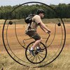
But then I got my first motorbike.
A very cheap and cheerful Lexmoto XTRS, looks the part, shame about its actual power :), but a decent first bike.
Only paid 250 quid for the thing. The previous owner was selling it as parts and spares and or as a project to do up... Well the bike was still fairly new and all that was really wrong with it was a broken flasher relay.
I wanted the Bike to also be a project to keep me busy, but so little needed doing with the bike I was done in no time. While riding around the yard testing out the bike I noticed the speedo and rev meter were really slow to catch up with the actual speed or rev. This bugged me and in the end decided to go ahead and start this project.
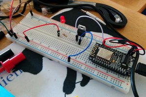
i don't have a lot of cash, but thanks to china and eBay i can get most of the parts really dirt cheap. Using Chinese clones of arduinos or maples. Even the 3D Printer I'm getting is a cheap Chinese thing. Reading up on it, it takes some work to get going but is a decent printer once its running.
This project has been going on now for a couple of months, so where am I at now?
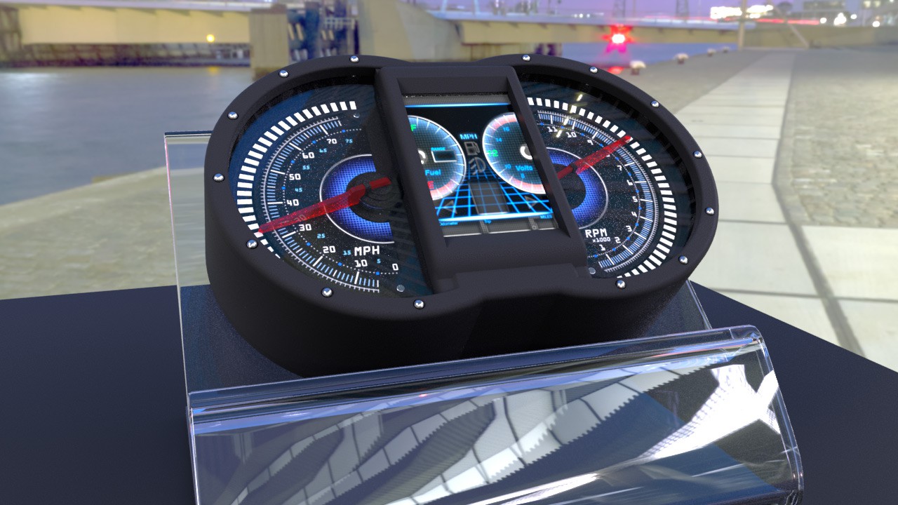
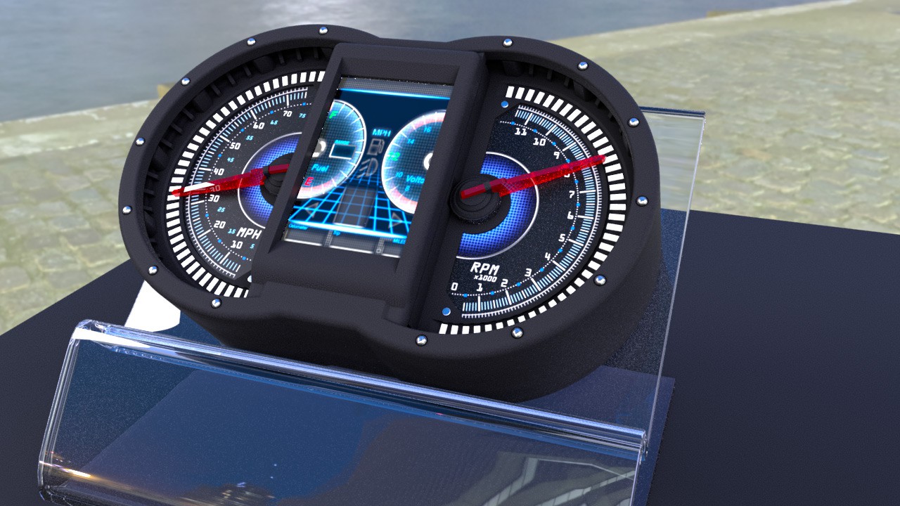
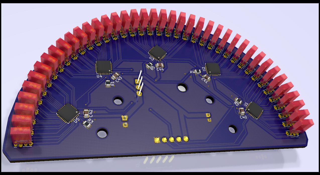
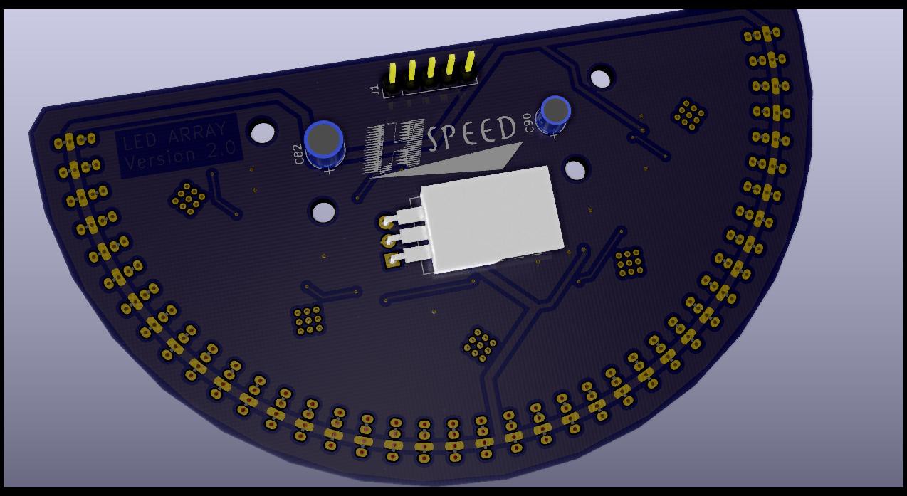
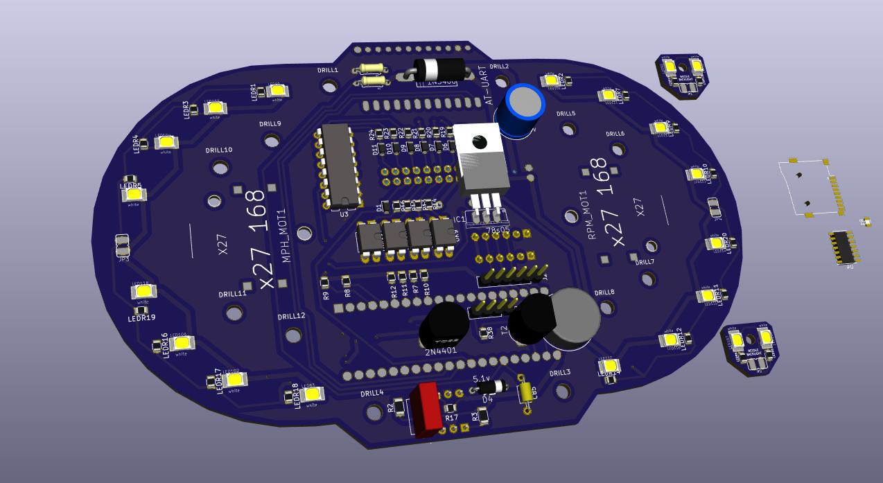
I have the speedo in a cardboard mockup, Its now reading real RPM data and displaying it with accuracy of around a 200 rev window. The LCD display is showing the numbers and the LEDs are keeping up with the pointers, currently only showing a white light...
I'm also more than half way done making the case design for printing.
What needs doing?
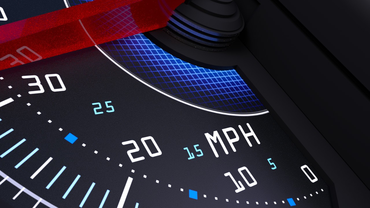
I want to make the LED display more interesting, throw in some colours and a peak lag animation.
I also need to design the casing that would hold the MPH sensor... Im going to use the bikes MPH cable from the wheel. Thats going to drive a fan that a optical cut off sensor would read, much like a mouse wheel does.
I need to work out how many slices in the fan I'm going to use. Too few the MPH update data would be a little slow and inaccurate. Too many the code might not be able to handle all the extra resolution and or the optical sensor might not be able to detect the brakes in the fan when the bike goes at top speed.
A little note, currently i have 80MPH and 12RPM on my speedo. Thats only because this bikes realistic top speed is about 65MPH and the rev counter says 12thousand RPM though I think more realistically its 10000...
This is a simple thing to change, in the sketch i only need to change 2 variables at the top of the sketch to take into account any changes. Then print out a new silk for the gauges.
Future plans for the project? Well after I finish V1, I also plan to build a GPS tracker that would go into the dash, for if the bike is stolen... But thats a whole different ballgame :)
I will try and keep things updated here as I go. Wish me luck


 WJCarpenter
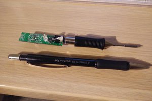
 HP (@banjohat)
 Michael R Colton
 Matt
Matt
hey! i have a circuit to be able to interface with the -neg trigger on the ignition coil if you want to take a look at it! Also, if you have any questions on how to integrate other sensors into your project i suggest looking into "seeeduino". Its a open source ECU. Look at there schematics. you will find how to integrate with water sensors air sensors etc!