Close
0%
0%

Soldering pen

Cheaper fine-pitch soldering setup with Wellers RT tips

Similar projects worth following
The soldering iron. One of the most used tools on the bench. We all have a preference for our own.

One of the problems is that a proper soldering station is quite expensive. Take the Weller XMRP for example. Amazing tips, fast heating and great for really fine-pitch work.
The tips are withing a hobbyist pricerange but the controller is expensive. Very expensive.
A few people have already built arduino based controllers for the tips. What I want is essentially that. But smaller.

This project doesn't claim to be anything it isn't.
It's not a big soldering station with all the bells ans whistles.
Instead it's a small PCB that will control a Weller RT tip and allow you to set the temperature within 10 degrees.
Also, it will allow the soldering tip to power down when you're not using it. in fact, about the same control as any soldering station. just smaller.

The project has its roots in the SMD soldering station by Martin Kumm

(http://www.martin-kumm.de/wiki/doku.php?id=Projects:SMD_Solderstation)

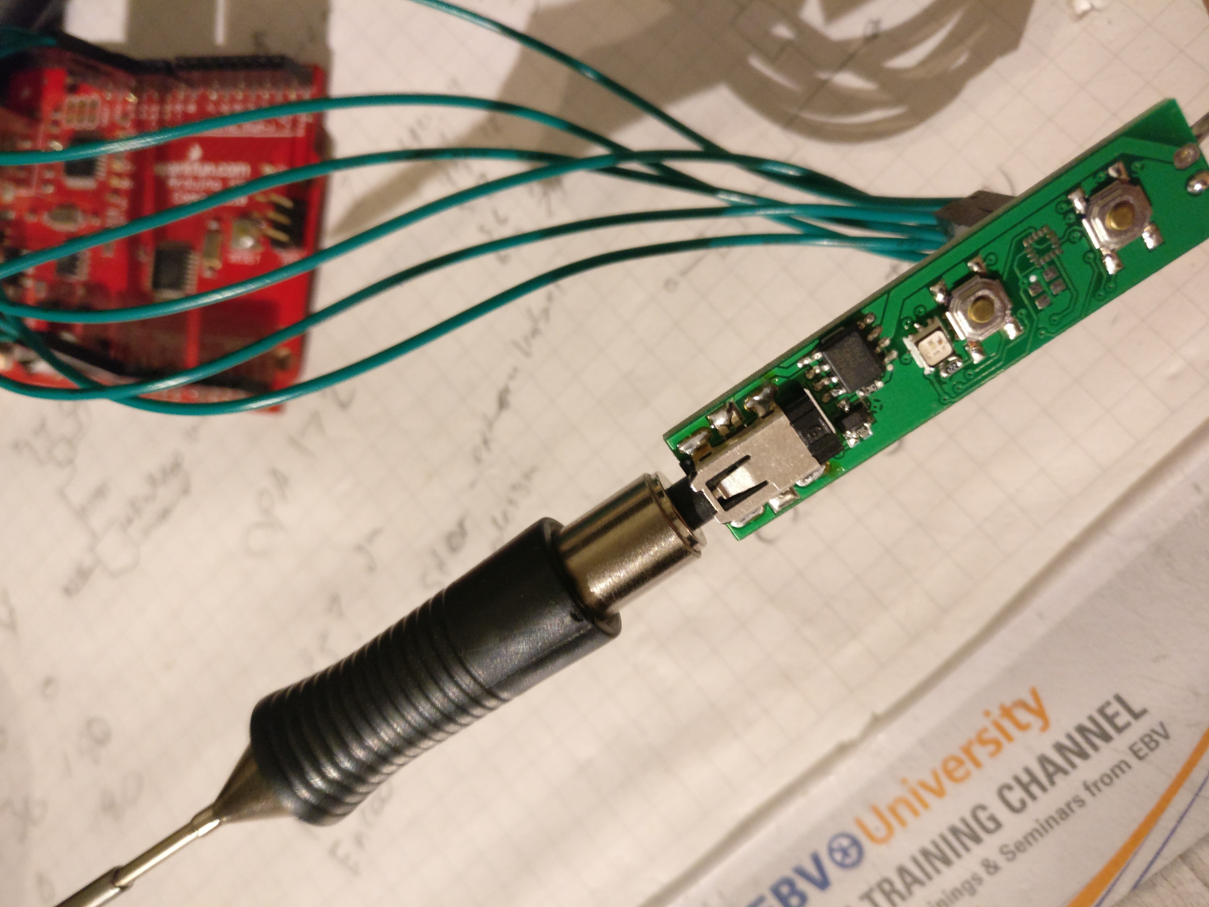
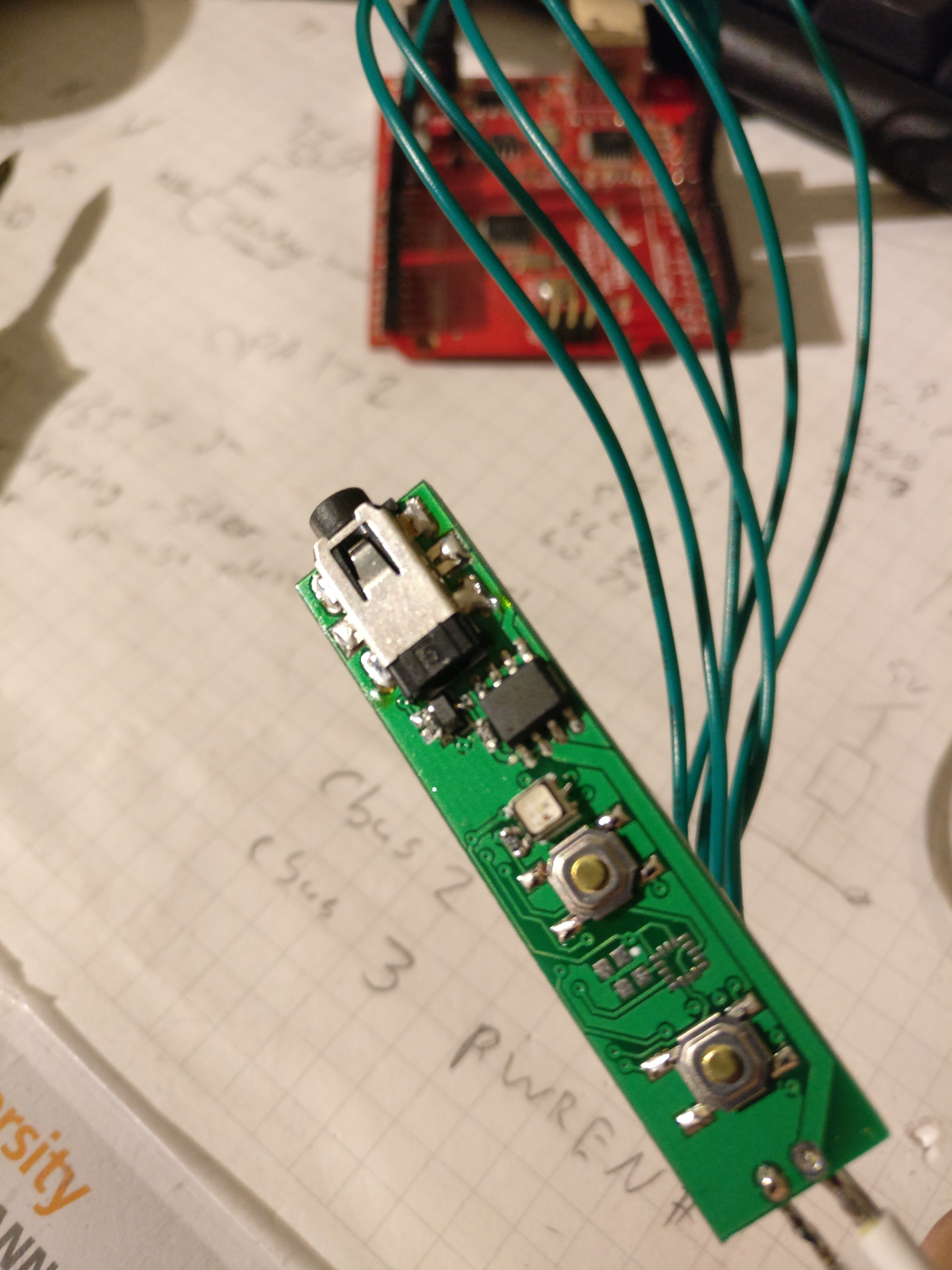
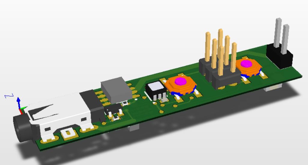
Some years ago I got a tray full of ATMEGA168's and since then I've always wonderes why people made shields for Arduinos. i mean, Just put the controller on the PCB when you're designing anyway. And since I got a bunch of them I might as well.

I figured that I didn't need a display for my soldering station. Why would I? I usually use the same temperature and only when soldering on large ground planes would I need some extra 'oompf'. For tasks like that I would usually take a bigger soldering iron anyway.

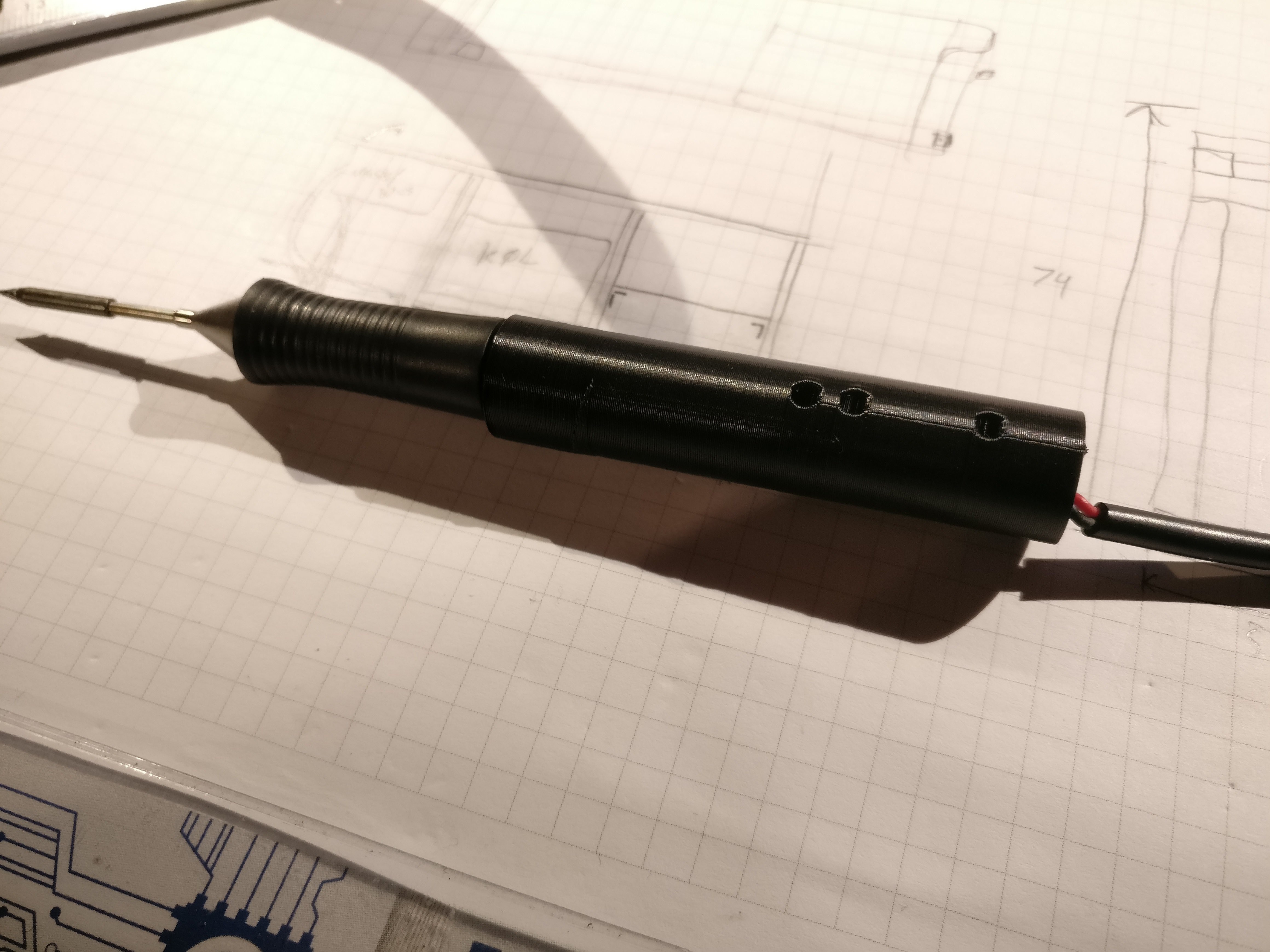
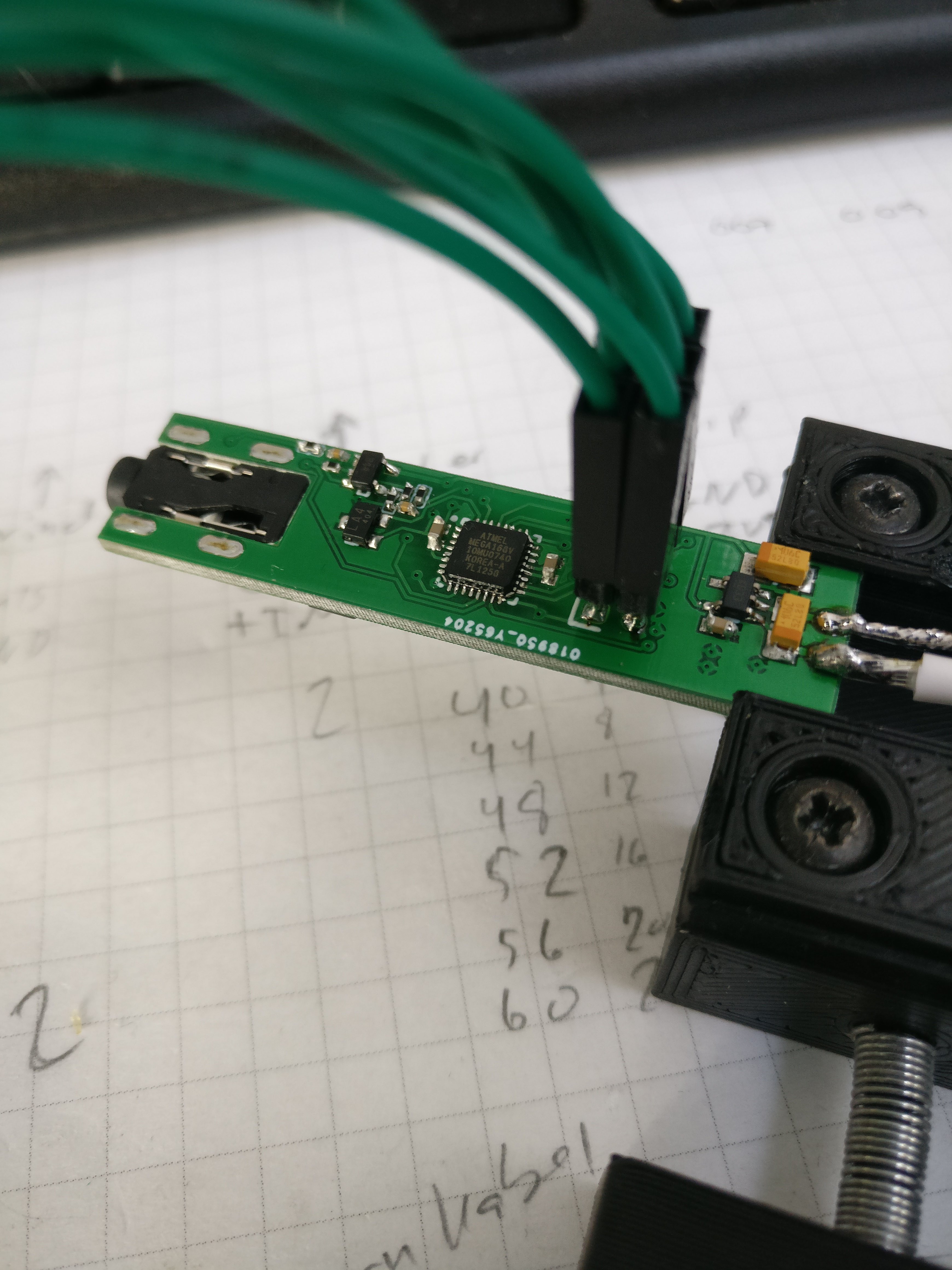
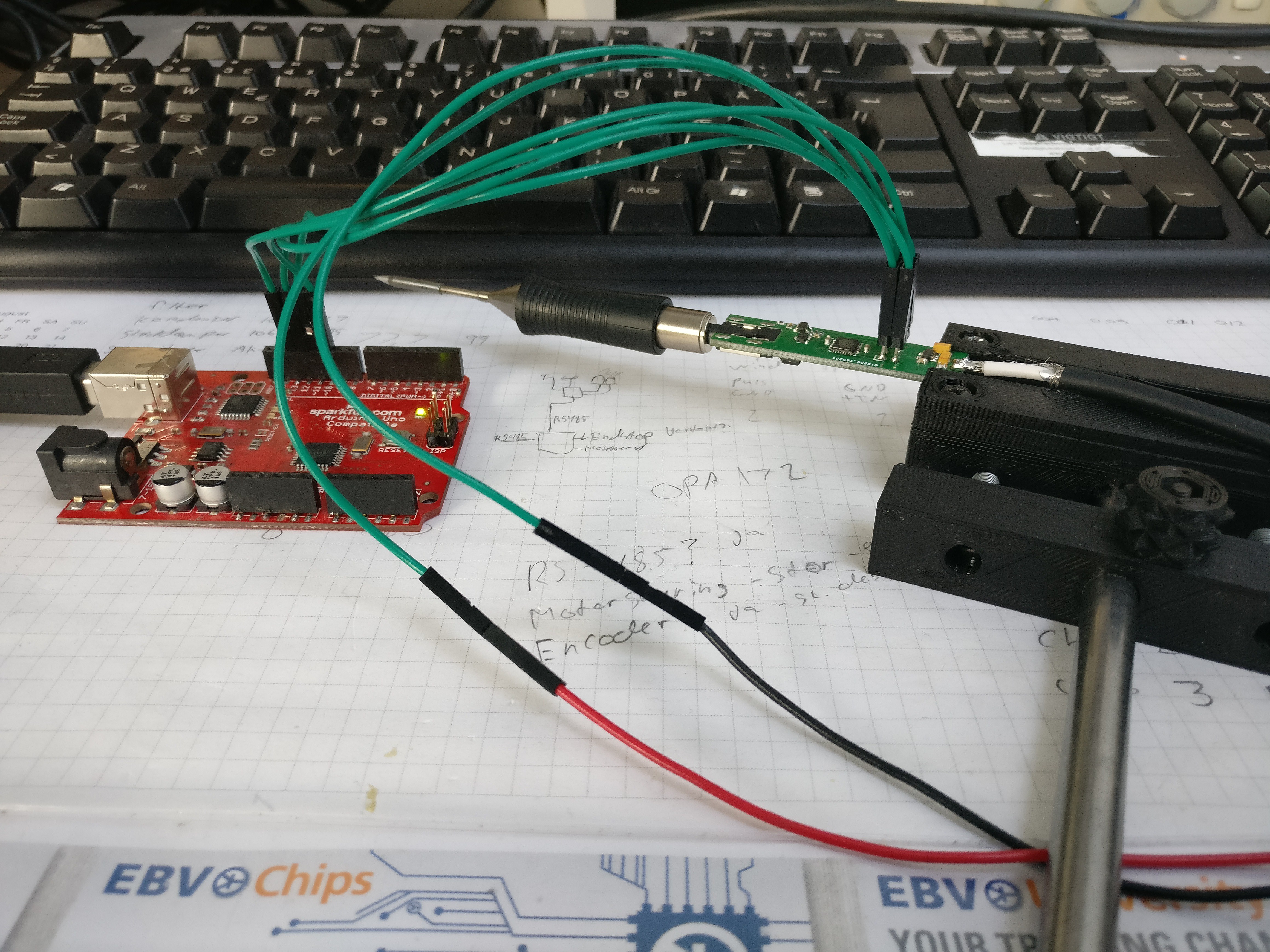
Thus the minimal soldering station was born. no display but with a USB interface for computer control.

the outline of the project was almost clear:

  1. Support Weller RT tips
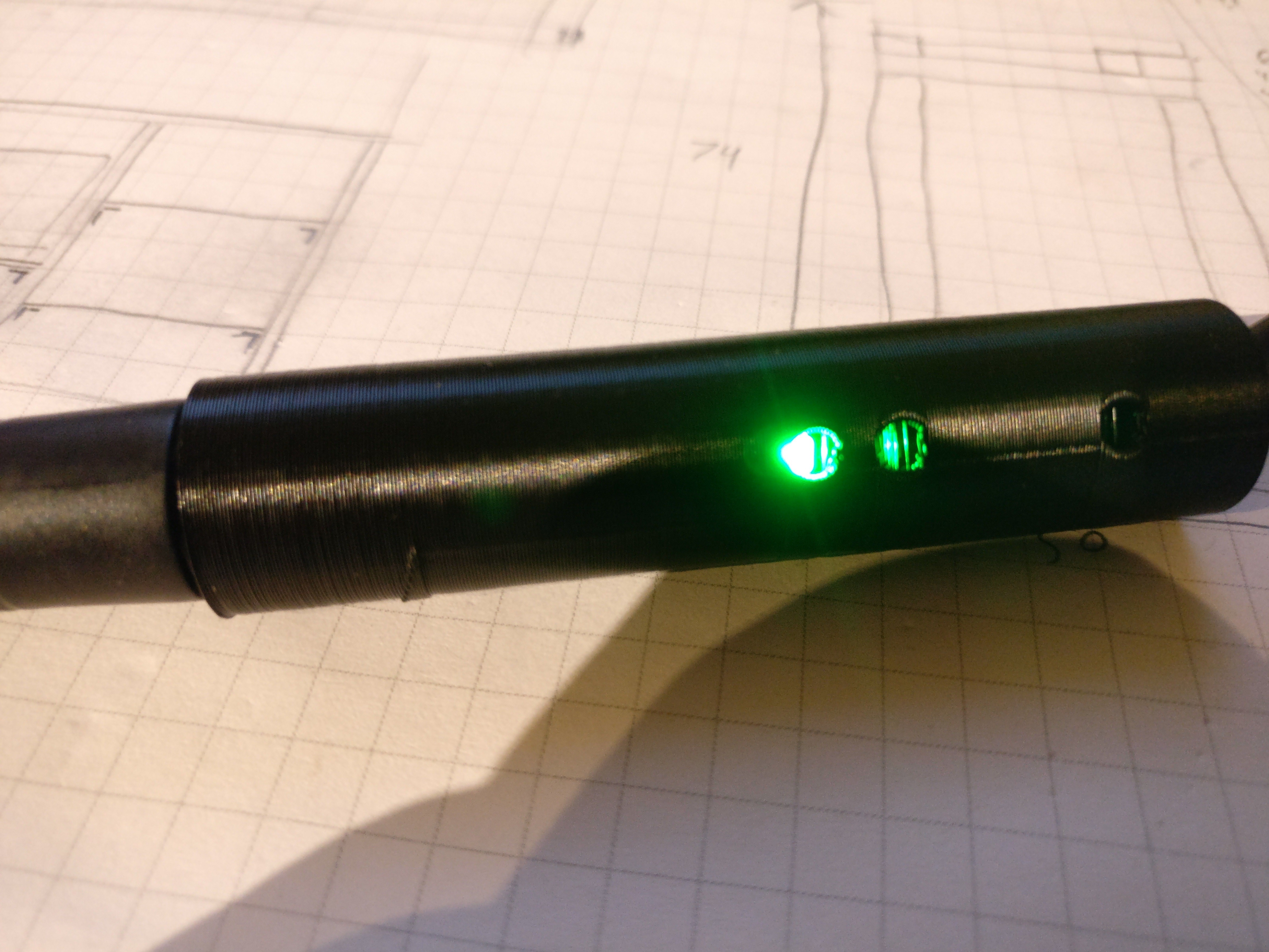
  2. Visual indication of heating and 'ready to solder'
  3. support cooldown switch
  4. store temperature in EEPROM

I sat down and drew a diagram.

  • 1 × ATMEGA168 Microprocessors, Microcontrollers, DSPs / Microcontrollers (MCUs)
  • 1 × OPA344 Amplifier and Linear ICs / Operational Amplifiers
  • 1 × IRF7416 Discrete Semiconductors / Power Transistors and MOSFETs
  • 1 × MIC5205 Power Management ICs / Linear Voltage Regulators and LDOs

  • Still going strong!

    HP (@banjohat)02/05/2018 at 12:58 0 comments

    I think this is one of the geekiest posts I've ever done.


    The soldering pen project is back on the table, after a trip round the moving box and then the drawer.

    I'm getting ready for the next (and hopefully final) firmware.

    This time it's about testing the hardware and a note-to-self about AVRDUDE.


    There's a lot of code snippet on this one and the formatting is getting screwed. Read the full post here:

    http://embryonic.dk/wordpress/?p=815

    I'm not sure about the timeframe but I still really want to get this going..

    Until next time!

  • Demo time!

    HP (@banjohat)11/25/2016 at 05:58 0 comments

    Hi everybody! I’m done. The soldering pen project is done. Well, At least in the first form where I feel I can release it to the public. A small beta-test have already given me changes that I need to implement before going to the next level and really trying to sell the pen but have a look at the video! I even found a case to ship it in.

    Now, I’ll let the video speak (that’s still me speaking though)

    Also - Check out my blog about this project - http://www.embryonic.dk

  • Programming a lot of boards

    HP (@banjohat)11/17/2016 at 09:53 0 comments

    Ever wondered how I'm going to program those small boards?

    I've made a video!


    Also - most of the information about the project will be maintained on my own website. http://www.embryonic.dk

  • Spending money

    HP (@banjohat)10/27/2016 at 08:36 3 comments

    I've just spend about 850$ on PCBs.. The soldering pen is going to production :)

    I still need to tweak firmware and make a programming jig. PCB's will arrive next week.

    Also this project will be further updated on my own site: http://embryonic.dk

  • Now with Casing

    HP (@banjohat)10/10/2016 at 12:02 11 comments

    It's been a while since I got the soldering pen to work.

    Now I'm back with more good news. I've printed the first casing for the electronics! Yes it might not be much but it's there! Looking more pen-ish than ever.

    What do you think?

    I haven't added buttons yet - they will go in the two hoels farthest from the tip.

    The hole closes to the tip is for a small light-pipe so the LED can shine through the casing. I was thinking some white PLA in 3mm would suffice.
    I'm still working on buttons. I'm not convinced that my initial idea will work so adding the buttons as small pieces of plastic might be the solution.

    Here the pen is heating. The red LED is really bright!!

    Next step is to convert all parts to 0603 so I maybe can have it produced locally. Also I will be extending the PCB beyond the 50mm limit I was currently working on, making room for a barrel jack connector for the 12V.

    I should make a gif.. the green is pulsing, indicating that working temperature has been reached.

    The biggest problem is now that the mini-jack connector is only rated for 1A and the tip is requiring 2A.. The connector gets warm.. I don't think I will have any luck finding a high-current low-profil mini-jack connector..

    Any thoughts?

  • It's alive!

    HP (@banjohat)09/08/2016 at 09:17 7 comments

    I know, I know - It's been a long time seince I've written (and done) anything on this project.

    A lot have happened although not that much on the project specifically. I got married, I've completed my laser cutter (at least to a stage where it can burn stuff) and a host of other things.

    I kept hitting a brick wall when I attempted to communicate with the MCU on latest revision of the soldering pen. I've given up hope of getting it to work.

    I considered going back to revision 2, but not having that slick low-profile mini-jack connector really bothered me.

    So, two nights ago a friend wrote me. We came across the soldering pen project and we discussed problems and solutions. Just out of curiosity I tried to solder a new MCU on one of the PCBs. Using AVRDUDE I read the fuses - It worked! I then tried to put a simple blink sketch using the Arduino IDE onto the chip. Bang. Dead.

    AVRDUDE couldn't see the chip anymore. Slowly it dawned that the fuse settings had to be wrong altough they were set right. To jump to the end of this: I think the unspecified fuse settings in the extended fuse caused some kind of lock-up in the chip. I don't have access to high voltage programmin equipment (such as the STK500) so trying anything like this was never in my head. I just assumed that the Arduino IDE would do the job. I have on several occasions had trouble with the right fuse settings through Arduino. Grrrrr!

    Then, yesterday my friend came by. We talked a bit more and we assembled yet another board. using the default fuse settings from an online fuse calculator (engbedded) we tried one more time with AVRDUDE. Contact. then again in AVRDUDE. still working. right, now we modified the Boards.txt file and tried, with caution, to download the blink sketch from the Arduino IDE. no problems.

    We read the fuses using AVRDUDE again. Still working.. wohooo!

    Quickly I soldered the RGB LED to the pads. put power back on. Bang! Blindingly red light - at least blindingly bright for a LED that size! blinking! It was Blinking! YES!

    Now for the Opamp and the connector to the tip. Set the temperature for 50 degrees and power on.

    The system didn't have the MOSFET so of course nothing would happen. I used the tip of my soldering iron to heat up the other tip. I could se the soldering pen go from red to green indicating that the temperature was reached. success!

    Now solder on the hall-sensor - Blue light indicating that the pen was hibernating was shown when I put a magnet close. Double success!

    Add the LDO regulator and attach 12V.

    Nothing. Quickly I disconnected the 12V again. something was wrong. I had to go to bed. dang - so close!

    this morning I fired up the sytem again, after checking that all connections was right. I had a voltmeter on the 3.3V line and it came up nicely. A splitsecond later the red diode went on. I had simply not waited long enough for the 12V supply (a brick) to power on. I adjusted the sketch to 350 degress and tried again.

    A quick puff of solder-smoke from the tip and a nice green glow from the 'ready' LED was shown.

    YES! IT'S WORKING!!! We're back in business!

    Now, since you've read so far, some pictures:

    The pen from the top side. The SOIC is the P-Mos for power to the tip. The RGB LED is right next to the lowest button.

    Close-up of the top-side of the PCB.

    Bottom-side. Those 0402 parts are tiny! I will change them for 0603 parts and add a barrel-jack (low profile?) for the power connector.

    Another full-system view. The arduino-as-ISP is shown for completeness. the voltmeter connections are the black and red wires going to the right.

  • The problem with real life

    HP (@banjohat)06/14/2016 at 12:14 7 comments

    The problem with real life is that it tends to get in the way of your projects.

    This update is far overdue - sorry for that! The paying projects (my job amongst other things) has been taking up most of my time. Also I'm leavning for a much needed vacation in a day. This all means that I won't be back until July to continue work on the soldering pen.

    So what have I managed to get done?

    Last time I wrote I was ordering PCBs. I have those - I've had them for a good month now. The trouble is programming the MCUs! I feel that I have tried everything. I have tried to solder all pins under a microscope securing all connections. I have assembled 6 boards but NO luck!

    I have only put on the MCU and the ICSP header. That should give me both SPI access and power for the MCU. But I must have been doing something wrong on the design.

    I have looked through the schematics but again - no luck. Everything seems to be in order - except is isnt. Could it be the MCUs? Maybe. I have them stored in a tray without any control of moisture. the tray is of the type with a small indent to keep each chip in place. a chip tray. it should be good enough, however I can't vouch for the chips. but that would mean that all my chips are fried. not a pretty thought.

    I know that this project has gotten a fair amount of followers since the start. Maybe some of you would like to have a look at the design? If you find an error I will send you a working PCB :)

  • New PCB ordered - Now with accelerometer

    HP (@banjohat)05/03/2016 at 11:04 0 comments

    I need a field for short updates, comment style.

    I have now ordered the Rev.3 PCB. I birefly covered a change to 3.3V internal voltage but didn't tell that much about the reasons.

    The reason (there is only one) is that I'm adding an accelerometer. Why you might ask? because my use-case has changed a little bit. I often find myself soldering in awkward spaces, close to the ceiling etc. therefore I might not have a magnet with me for turning the pen into standby-mode. the solution is therefore to have an accelerometer with tap detection so I can just do a double-tap and the pen will turn off. another double tap will turn it back on. The LED will provide the visual feedback I need to see if the command is received properly. In the end it's just an on/off state trigger. The hall sensor will provide the same feedback and the last input will provide the signal change.

    Well, That's all for now. carry on!

  • A new PCB and a new CAD

    HP (@banjohat)04/26/2016 at 12:39 4 comments

    One of the fundamental ideas with the soldering pen was to have a small package and a 3d printed casing for the whole project. I don't know how it happened but somehow I completely missed the fact that the jack connector was not in the same plane as the board. of course. therefore I decided to look for a very low profile connector instead.

    The first and second revision of the PCB showed that the principle was working. I could (easily) make a soldering pen with a small footprint and a nice set of features. Now I could focus more on the mechanics of the project.

    I've found the connector: CUI SJ-3502-SMT. It's only rated for 1A but so is most of the jack connectors I can find. My biggest problem: slotted holes!

    It turns out that DesignSpark PCB can't do slotted holes! Argh! Somehow I've always managed to get around this until now, but this was very much needed. What should I do? A new CAD tool is not a very funny solution.

    Anyway I decided to have a look and I found CircuitMaker - the 'free' version of Altium, that in return requires that you store your project publicly. Fair enough I'm all for open source anyway and having a platform to share from is not that bad. At least I knew that I could get my slottet holes.

    Fast forward 2 days and I've found out that Circuitmaker gets compoent specifications and footprints directly from octopart. this is insanely nice - crazy nice! beacuse that means that when I'm done with a component it will be shared for everybody else to use. voilá, a single global component library. wow!

    Also Circuitmaker, being Altium under the hood, of course works in 3D. So almost all components have 3d models attached.

    Look at this:

    Isn't that beautiful?

    The new low-profil jack connector is clearly visible and I've changed the LED to a SMD version.

    I'm really close to removing the programming header and replacing it with.... something smaller. I have an idea for something that could fit in that space..

  • Take a stand...

    HP (@banjohat)04/16/2016 at 12:48 3 comments

    This is exactly why I love 3d printers. When you have an idea you draw it and then you print it. Simple as that.

    Of course the soldering pen needs a stand. And why can't it be printed?

    I know that a lot of people will tell me that it will melt and maybe they're right. But I havent seen them print a stand for their soldering pen yet. So here goes:

    It shows some problemswith the board layout of the pen. for example the hall sensor for standby detection is located a really stupid place - in the opposite end of the tip. Why is this a problem? Well, the support containing a magnet for the hall sensor to detect has to be really long!

    For now I have chosen to move the magnet 20mm downward but of course there's no hall sensor there right now. Luckily I will do another PCB revision because I want to change the mini-jack plug to a different model that will keep the connector on the same plane as the PCB. This is another story but it will make it possible to have a round casing on the pen. it will be more pen-like.

    I'll conlude this log with a picture of the stand with the pen inserted. haven't turned the thing on yet. Soon. very soon :)

View all 14 project logs

Enjoy this project?

Share

Discussions

Remenje wrote 07/11/2018 at 10:14 point

Why did you invent soldering pen and what is the significance of that?

  Are you sure? yes | no

Martin wrote 02/05/2018 at 17:41 point

Have look at the TS100. A nice soldering pen for 12V to 24V

  Are you sure? yes | no

HP (@banjohat) wrote 02/05/2018 at 19:04 point

I'm familiar with the TS100. However I really like the RT-tips from Weller and they come in quite a wide range. The TS100 is a nice soldering iron and I won't be able to compete with the pricing of it but the soldering pen is something I made myself :)

  Are you sure? yes | no

Martin wrote 02/06/2018 at 10:59 point

I did not think that you know it, because your project looks SO similar. I strongly loose motivation to make something, if I see, that I can get more or less the exact same thing for e.g. half the price ready made. But if you do not see it as being the same - and have fun doing it - then it's "another story".

  Are you sure? yes | no

HP (@banjohat) wrote 02/06/2018 at 11:30 point

The problem is really that you can get most things cheaper if you can just live with it being the way someone else made it. The whole idea behind the project is that I wanted a minimal soldering station. I don't need a display. I don't need to be able to adjust temperature in single degrees. I do, however, want the RT tips. I started this project more than a year ago, more likely 2. I don't recall the TS100 being around then and also - I really don't want that OLED screen...

  Are you sure? yes | no

jacob.scherer wrote 01/16/2017 at 00:29 point

Do you have any updates on this project? I would love to have one for my RC Field Kit!

  Are you sure? yes | no

HP (@banjohat) wrote 01/24/2017 at 13:54 point

Hi, Sorry for the delay (I have been super-busy with this 'life' thing).

So- the current status is still that the first version is done. It is 12V only and have some overshoot when heating the first time (from room temp). 
There have been some questions on the firmware which I plan to present, when I have the next one ready. 
I'm currently building the next batch of 5 pens on which I can develop the code further. I can sell these but you would have to upload new code yourself...

  Are you sure? yes | no

MikeM wrote 11/11/2016 at 07:30 point

Hi 

Is there programing - an ino or hex avalible? 

  Are you sure? yes | no

HP (@banjohat) wrote 11/17/2016 at 09:54 point

Hey, sorry for the late answer - Yes, I will release some sort of code but I wan't to have the feedback from some testers before I will post it online.

  Are you sure? yes | no

Cereyanlı Şeyler wrote 08/10/2016 at 09:36 point

How was your holidays ? Did you have a chance to re-visit the project so far ?

  Are you sure? yes | no

Raymon458 wrote 07/03/2016 at 17:07 point

can you share stl file of the soldering iron stand? it really looks great

  Are you sure? yes | no

HP (@banjohat) wrote 07/04/2016 at 16:47 point

yep - here you go :)

scad format

https://github.com/HansPeterHaastrup/SolderingPen

  Are you sure? yes | no

Cereyanlı Şeyler wrote 05/18/2016 at 09:24 point

Your project looks quite interesting and appealing. Are you planning to put files out once you finished or selling kits ?

  Are you sure? yes | no

HP (@banjohat) wrote 05/18/2016 at 15:22 point

Thank you very much!
Yes, I'm planning on both. I've just received the new revision of pcbs today so I'm hoping to have a system running in a few days :)

  Are you sure? yes | no

Cereyanlı Şeyler wrote 05/27/2016 at 14:24 point

Any updates on the status ?`

  Are you sure? yes | no

HP (@banjohat) wrote 05/27/2016 at 14:30 point

Only a little - I've got new PCBs and got hold of the mini-jack connectors. I have soldered the MCu on three boards but somehow managed to screw something up with the ISP connector - I haven't ben able to communicate with them yet. It might be a soldering issue. I'm looking to solder a few more and inspect them thorougly.

  Are you sure? yes | no

Cereyanlı Şeyler wrote 06/14/2016 at 11:56 point

How is it going with new PCBs and programming MCUs ?

  Are you sure? yes | no

HP (@banjohat) wrote 06/14/2016 at 12:15 point

Sorry for not replying - The new project log should clarify a bit...

  Are you sure? yes | no

René Arts wrote 06/30/2016 at 09:28 point

Busy times for you, it seems. Have you been able to have a look at the comment I made on your last log?

  Are you sure? yes | no

pescadito64 wrote 04/27/2016 at 13:43 point

hey, i receive your answer to 'cheap usb tip' .... but it doesn't appear here at discussion tab (https://hackaday.io/project/10140-soldering-pen/discussion-54893)

you right, it doesn't have a temperature sensor, but what about adding a multimeter temperature probe (k termocouple) .... (i falled in love with that cheap tiny tip...)

  Are you sure? yes | no

HP (@banjohat) wrote 04/27/2016 at 16:31 point

strange - I can see the whole thing on (https://hackaday.io/project/10140-soldering-pen/discussion-54897). Well, I'd still need to integrate heating element along with the thermocouble = more components and heat management for me ;)
I still have a wider range of tips to chose from by using the RT tips. But hey - You can get the design and go nuts :) It's just a matter of starting a new project :)

  Are you sure? yes | no

pescadito64 wrote 04/27/2016 at 12:03 point

Hi HP, you have a really nice solder. Well done!

But what about using a more cheap usb solder tip (http://www.ebay.com/sch/i.html?_from=R40&_sacat=0&_nkw=8w+usb+soldering&_sop=15) instead of weller tip. And what about using 5V, 7.2V battery pack or 12V. May be could be nice improvements for Version2.

From my part I'm ready to buy that nice cheap tips right now.

  Are you sure? yes | no

HP (@banjohat) wrote 04/27/2016 at 12:53 point

The problem is that those tips are... just tips.. The Weller tips have Heating element and temperature sensor in the tip istelf. The interface is very simple (minijack) and the tips are available in a lot of different sizes.
I'm already thinking of using a batterypack as power supply and I'm thinking of runnning all the controls on 3.3V to be able to use a USB power bank. it will affect the heating time, but it's still quite fast.
Adapting to 3.3V on the control side would still allow for an inpit voltage of 12V though!

  Are you sure? yes | no

lucastonaco wrote 04/23/2016 at 19:47 point

Your project is very nice! this is very interesting for computer technicians and electronics ... !

  Are you sure? yes | no

Markus wrote 04/21/2016 at 06:50 point
Very nice project. Will you share your design and the software?
That little soldering pen is really interessting and amazing.

  Are you sure? yes | no

HP (@banjohat) wrote 04/21/2016 at 07:14 point

Yes I will :)

Currently I'm working on getting a new revision of the hardware ready with a jack connector in the PCB plane. Also I'm changing from DesignSpark PCB to CircuitMaker (the community version of Altium). When that design is done I will upload initial code to github. Right now the code is not very fancy. I'd like to have it a bit more.... 'finished' before showing it to everyone ;)

  Are you sure? yes | no

Ranko wrote 04/16/2016 at 17:34 point

Very nice project and simple design.

Which hall sensor you use?

  Are you sure? yes | no

HP (@banjohat) wrote 04/17/2016 at 09:48 point

It's a TCS20DLR,LF (RS# 796-5399) in a SOT-23 package. It was a last minute change because the fab house had some questions requiring a new data package

  Are you sure? yes | no

zeniaschelske wrote 03/24/2016 at 07:05 point

Wauw !

Now you can really see where this is going.

I am a big fan of how elegant this design will be compared to the old soldering iron hampered by the station.

If you got room for a pen, you got room for a soldering iron ;) A Soldering Wiz on the go!

So far the design also looks lighter than the original for grace of the wielding.

I am looking forward to see the realization of this project!

  Are you sure? yes | no

pescadito64 wrote 03/24/2016 at 05:20 point

Hey, a really simply design that i would love to try!!!

Please, could you tell us the temperature range the solder can support?, Also, could it work with another tips like HAKKO T12/T15 or 907?  What modifications could be needed?

  Are you sure? yes | no

HP (@banjohat) wrote 03/25/2016 at 17:19 point

Thanks for the support!

The weller tips (when attached to the real station) is good for up to 400 - maybe 450. The tips should have a reasonable life because they cool down when they're not in use (in the holder)

I don't think it will work with the hakko tips. The reason this project works is that the Weller tips have the heating element built in along with a thermocouple (type K). If you can find tips with the same, then you should be good :)

  Are you sure? yes | no

René Arts wrote 03/23/2016 at 21:47 point

Wow, this is going places! The new formfactor looks great. I'm really curious about the soldering capabilities of this little marvel. Are you planning to do some tests anytime soon? A short demonstration video would be very appreciated :)

Just have been looking at some Weller RT tips... I found that they aren't that much more expensive than the JBC's, so I might order one or two sometime soon; I really like your project (I bet you guessed that already, hehe) and would love such a nice and small soldering pen-to-go. 

  Are you sure? yes | no

HP (@banjohat) wrote 03/25/2016 at 17:22 point

Thanks! Funny thing is that I have being using the tip for soldering the MLF package on the PCB. the chicken and the egg ;)
I'll make a video for you soon I promise!

I'm glad you like it! I still have some work to figure out - casing (3d print) and controls (buttons and hall sensor) Firmware should be pretty straight forward after all...

  Are you sure? yes | no

René Arts wrote 03/28/2016 at 15:33 point

Using the tip (with the prototype board?) to solder it is off course great recursive hackery; just like a simple compiler to compile its newer offspring. Looking forward to the video! 

  Are you sure? yes | no

Eric Hertz wrote 03/22/2016 at 14:22 point

Hah! Weller without a Weller station! Who'da thunk...?

  Are you sure? yes | no

HP (@banjohat) wrote 03/22/2016 at 14:30 point

I think it's going to be a pretty nice addition to my mobile toolkit! I mean, everyone have a 12V adapter lying somewhere.. so power is not an issue.

  Are you sure? yes | no

HP (@banjohat) wrote 03/18/2016 at 12:32 point

thanks! I've had the idea for a simplfied soldering station for a while but didn't have the time to draw the design before now.
Oddly enough I just found the seeedstudio mini soldering iron a couple of days ago and had the same thought. I like the Weller tips and have been using them on my job a lot.
Yes, you're correct, the power is 12V supplied by a barreljack in the end of the pen. I guess that the pen should be able to run on higher/lower voltages as well but first I'll have to have PCBs in my hands :)

  Are you sure? yes | no

René Arts wrote 03/18/2016 at 12:20 point

Hey there, congrats with this nice idea; I really like(d) it. 

Looks a bit like the simplified version of the SeeedStudio mini soldering iron, though with a lot better/replacable tip. Just a few questions; I guess the power supply is going to be a standard 12VDC supplied by a standard connector? 

Would it be possible to convert the design (or use a conversion cable, I won't mind) with a  to use JBC soldering tips, the JBC tips are mighty fine as well and possibly a bit cheaper.

Did you consider using an ESP8266 instead of the ATMEGA168? It has about the same component size and can easily do job as well and even more; add an optional web interface to it to update and view settings via i.e. a PC or smartphone. Although the ADC is limited, that might pose a bit of a problem. 

Really looking forward to your next blogs!

  Are you sure? yes | no

HP (@banjohat) wrote 03/22/2016 at 14:33 point

Hey! Sorry for not answering all your questions. I see that your comment was larger than I though.. I don't know the JBC tips but as long as the tip has integrated heating element and temperature sensor you should be good to go. you might want to change parameters for the thermocouple but that should be all.

the ESP8266 is actually a nifty idea! on one hand I like that my soldering iron could hos a small web page but on the other I don't want to over complicate things. I don't think ADC resolution would be an issue. both chips are 10 bits right?

  Are you sure? yes | no

René Arts wrote 03/23/2016 at 11:53 point

The JBC tips feature a thermocouple type sensor (AFAIK placed far into the front of the tip, which is excellent), so that shouldn't pose too much of a problem. While looking for projects like these I stumbled upon a very nice project of a soldering station capable of using Hakko, Weller and JBC tips: http://dangerousprototypes.com/forum/viewtopic.php?f=56&t=7218&p=61175&hilit=soldering+jbc+weller#p61175 It's a way more complicated design than yours, but it might yield some usefull information. 

The ESP8266 has a 10 bit ADC, but a problem might be that it only can measure between 0V and 1V. One of the nicest features of it is that it can be programmed via the Arduino IDE, however it is a 32bit uC and runs at 80 or 160MHz.

The whole webinterface stuff can be optional/done later (I'd be happy to help you out with that!), but over-the-air firmware updates could be very nifty as well (who even needs ICSP ?;-) ). 

  Are you sure? yes | no

HP (@banjohat) wrote 03/23/2016 at 13:23 point

That's an impressive soldering station! I do however don't want to have the big display and box on my desk - hence my smaller project. thanks for the link! definetely useful :)

The 0-1V limit shouldn't be a problem - it's just a matter of adjusting the bias (and maybe having the right opamp that will work all the way down there, while being single-rail.
The only thing would be power consumption but it's not really an issue. just more like a thought. I don't need that big of a controller for my project ;)
OTA would be awesome! I love the idea! but then again - need to have or nice to have...

  Are you sure? yes | no

Similar Projects

Does this project spark your interest?

Become a member to follow this project and never miss any updates