 Patrick Van Oosterwijck
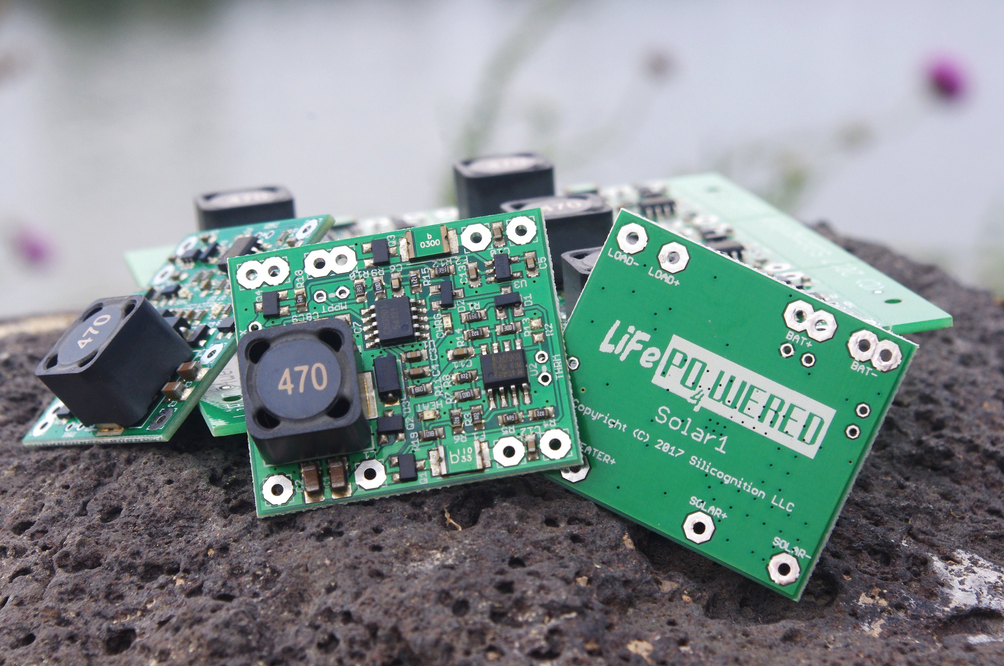
Finally got around to taking some product pictures and writing enough documentation to be able to start selling the prototypes I built on Tindie!
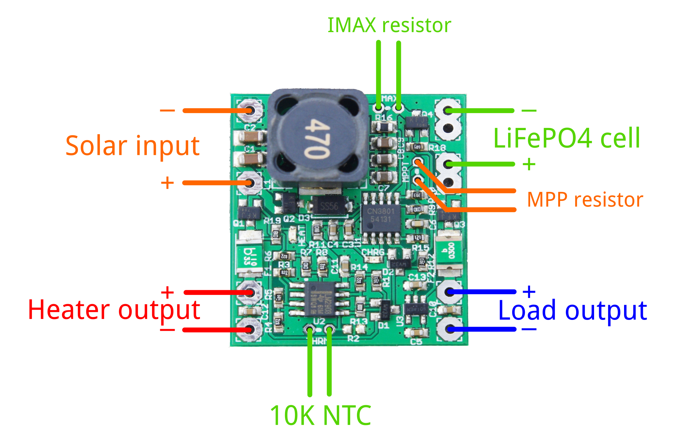
Hopefully with the connection diagram and design information it will be possible for most people with some electronics background to use these successfully.
I'll duplicate some of this information here for those interested in how to make use of this board:
Calculating MPP resistor
To extract the maximum amount of power from your solar panel, you need to customize the maximum power point setting to match that of your panel. Use the following formula to calculate the value of the MPPT resistor:
MPPT = 120500 / (Vmpp - 4.295)
Some examples values from my own testing with different panels:
- 6V panel, Vmpp = ~5.2 V -> MPPT = 120K
- 9V panel, Vmpp = ~8V -> MPPT = 33K
- 18V panel, Vmpp = ~16.2V -> MPPT = 10K
Customizing maximum charge current
There are many ways that charge current is limited by different parts of the system, so often it's not necessary to worry about limiting the maximum charge current. For instance, even in the brightest sun, the output power of the solar panel may be limited to the extend that the charge current never reaches the limit of the battery. You can check this by taking the wattage of the panel, and using it to calculate the theoretically maximum charge current (Icharge = Ppanel / 3V).
If you find you do need to limit the current, you can calculate the maximum current as follows:
Ichargemax = 0.12 / Rsense
Rsense for different default charge current versions I have for sale:
- 3.07A: 0.039 ohm
- 2.35A: 0.051 ohm
- 1.93A: 0.062 ohm
- 0.5A: 0.24 ohm
The maximum charge current can be increased by adding a resistor IMAX in parallel with the sense resistor already present on the PCB. The new sense resistance can be calculated by:
Rsense = Rdefaultsense * IMAX / (Rdefaultsense + IMAX)
You can then use this new Rsense value to calculate the resulting charge current limit.
Thermistor
A 10K NTC thermistor needs to be connected for the system to operate correctly. The system has been designed for thermistors with a B value of 3950, but reasonable performance can be had for B values down to 3435. There is a footprint for surface mount (R2) as well as through hole (THRM) thermistors. Only one of them should be used at a time.
Many battery packs come with a 10K thermistor built-in, and connecting this thermistor to the charger is the ideal situation. If no thermistor is present in the battery pack, we sell a thermistor with 8 cm leads that can be taped to the battery pack. A surface mount thermistor on R2 may work if there is little temperature difference between the PCB and the battery. If you don't want thermal protection of any kind, a 10K resistor can be installed instead of a thermistor.
Below are calculated threshold levels for different B values of the thermistor:
- [B value 3950] Under temp limit: 0.2°C (falling), 0.7°C (rising) - Over temp limit: 52°C (falling), 58°C (rising)
- [B value 3435] Under temp limit: -3.2°C (falling), -2.6°C (rising) - Over temp limit: 57°C (falling), 64°C (rising)
Battery heater
In under temperature conditions, the solar panel's voltage is applied to an optional heater connected to the HEATER pads. This can be used to bring the battery up to temperature before charging is started, ensuring that no low temperature lithium plating occurs and thus maximizing battery life.
In its simplest form, the heater can be a power resistor thermally connected to the battery pack. Since no MPP is maintained, the user needs to take care to choose the resistor value so it will not collapse the solar panel voltage under reasonable light conditions where enough energy is present for heating, while at the same time ensuring it doesn't pull more than 1.1A under ideal light conditions.
Limitations
- Does NOT come with a battery, this one is BYOB (Bring Your Own Battery).
- ONLY use LiFePO4 batteries, no other Li-ion or LiPo!
- Only use a single cell 3.2V LiFePO4 cell, or place cells in parallel to create a larger capacity LiFePO4 battery that still has 3.2V output voltage. Cells in series are NOT supported.
- The load output has a 3A thermal fuse, the heater output a 1.1A thermal fuse.
- If you don't connect an MPP resistor, the MPP voltage will be 4.295V. Unless you have a 5V solar panel, you will not extract energy from the panel efficiently.
- If you don't connect a thermistor, the system will be in under temperature protection.
- Don't trust your solar panel spec, it is likely highly overrated. Do your own testing to find maximum power output and maximum power point voltage. In reality you can expect about 70% of rated power.
Discussions
Become a Hackaday.io Member
Create an account to leave a comment. Already have an account? Log In.