0%
0%
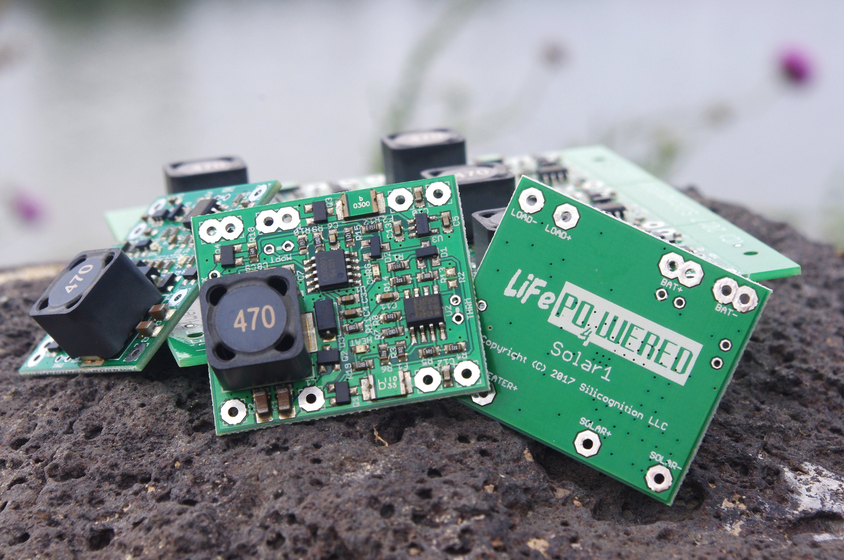
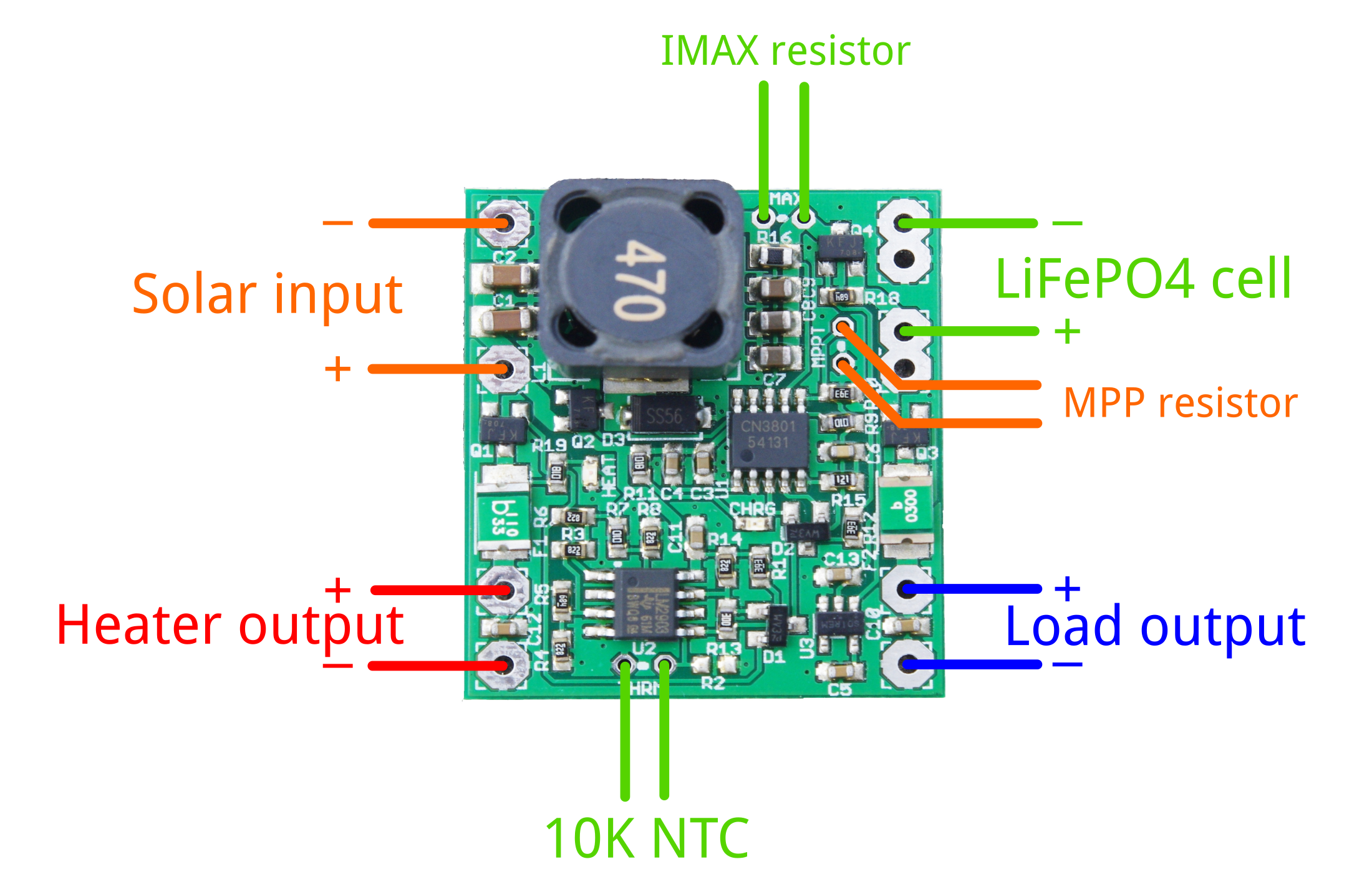
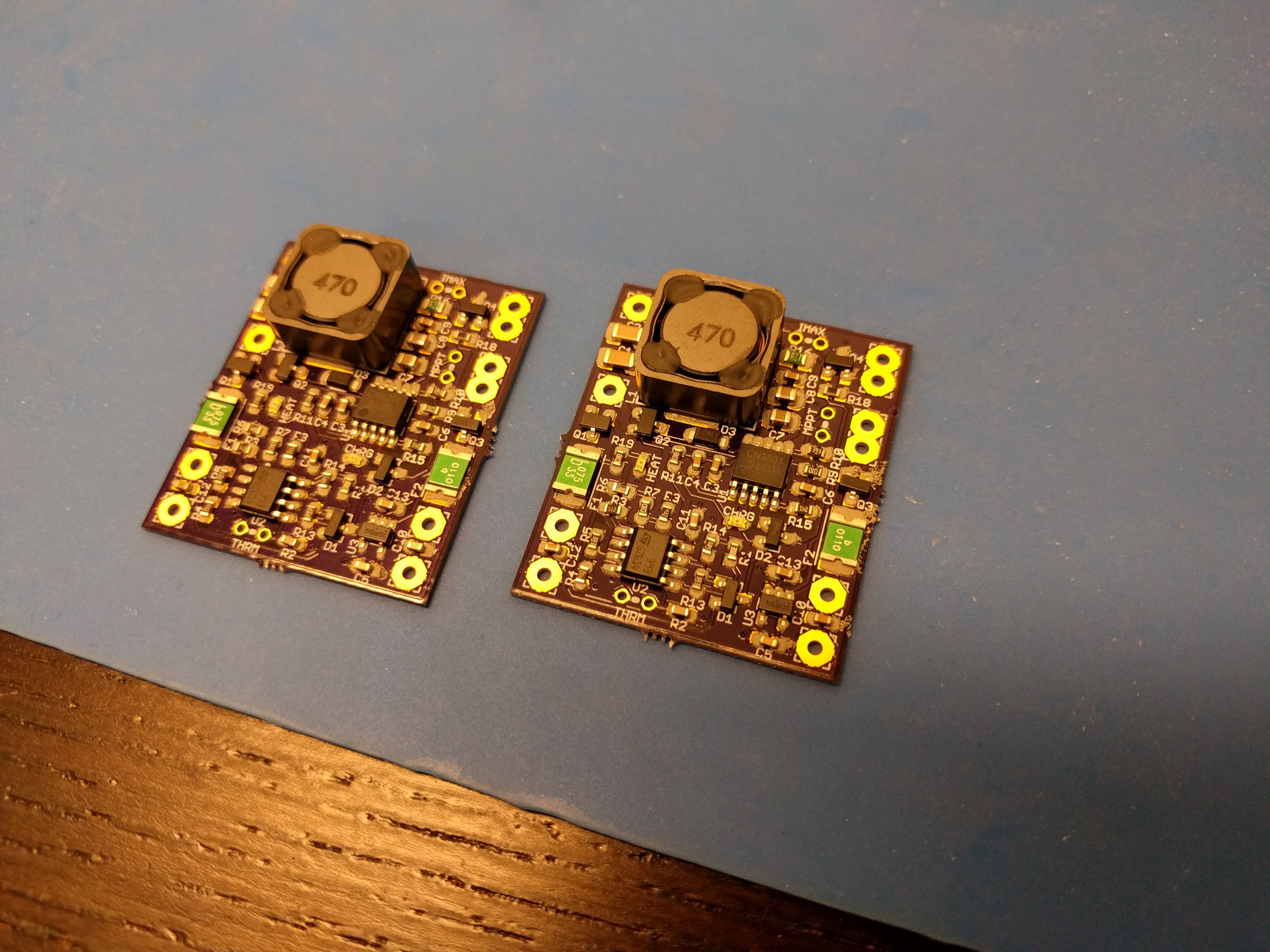
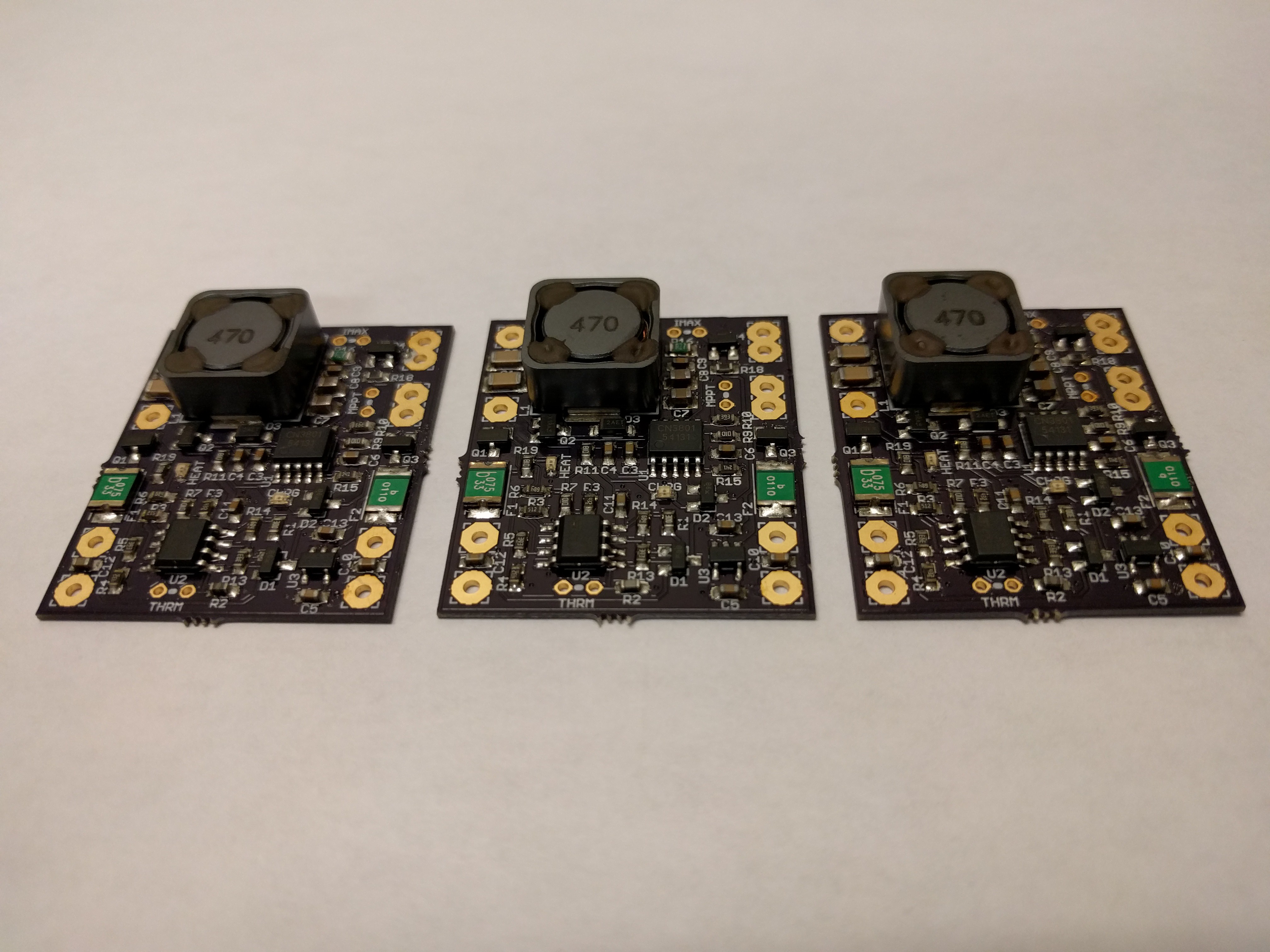
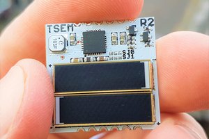
LiFePO4wered/Solar1
A complete LiFePO4 based solar power supply for IoT devices
 Patrick Van Oosterwijck
Become a Hackaday.io member
Already have an account? Log in.
Just one more thing
To make the experience fit your profile, pick a username and tell us what interests you.
Pick an awesome username
hackaday.io/
Your profile's URL: hackaday.io/username. Max 25 alphanumeric characters.
Pick a few interests
Projects that share your interests
People that share your interests


 mr.jb
mr.jb
 Jasper Sikken
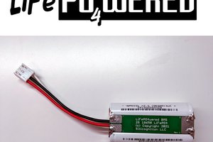
Does anything speak against implementing a load sharing circuit between the battery output and a 3.3V source (5V USB + LDO) to be able to power the load from USB also.
Great board thx for your effort ,want to use it for weather monitoring in the field.