Giovanni Leal
-
Building the Palm
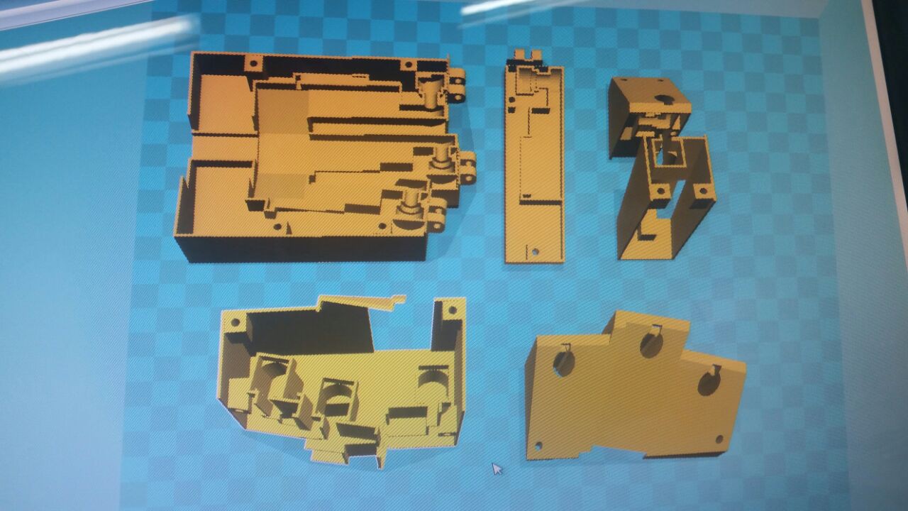
09/06/2016 at 15:34 • 0 commentsNow that we had a reliable linear actuator ( we thought that!!! but you will see) we started to think about the whole hand and to do this we had to place all the mechanics of each finger, sculpt a shape that includes all the components and pleases the eye and finally cut it into tree pieces with the corresponding holes for the screws (we utilized the screws from the servos, we had a bunch and they are great).
So about the first thing that everyone always asks. Why fourfingers?
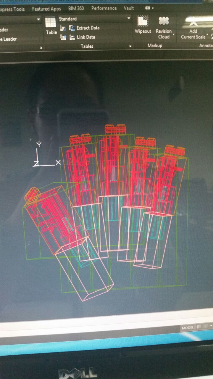
Well we always try to consider every input and we really tried in our earlyest version to find a good reason for keeping all the five fingers. Indeed there is the proof about that.
![]()
![]()
We cramp it up all inside but the real question was. Is there anything that you NEED five fingers for?
The extra finger adds cost, weight, complexity to the design and build of the hand. Think about it, those are the big cons of a myoelectric prosthetic hand that we want to change. We want to offer a cheap light weight prosthetic, also we don't want to build something that seems that you have a natural hand that not the goal, we hope that the people that wear this prosthetic wear it proudly because you have a freaking robotic hand.
So we needed inspiration and started looking for it. The design for everything was up for votes on the different areas of the company.
Mock ups like this were rotating constantly asking, which do you like the most?
![]()
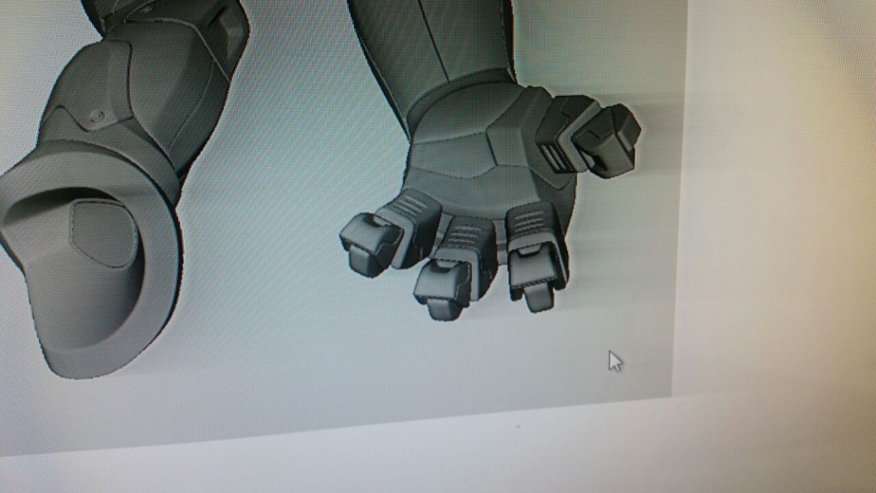
We found a design for an alien for a game that really caught our attention an gave us some idea for the proportions of the fingers if we wanted to make it appealing. We also consulted physiciansand a bunch of anatomy books so don't worry.... that much.
![]()
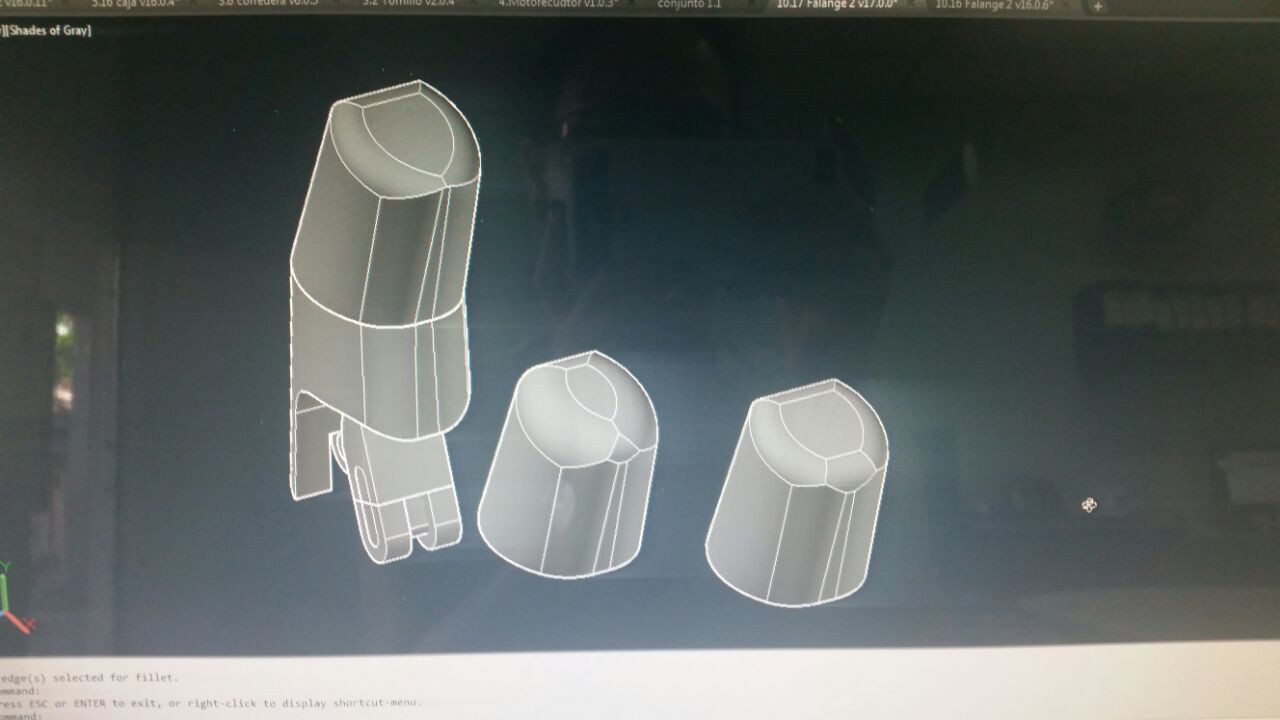
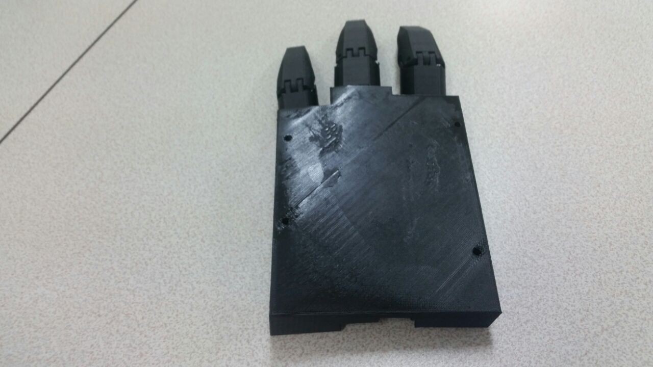
But first... we wanted proof of concept. So meanwhile the design was taking place, a basic functional palm was getting printed.
![]()
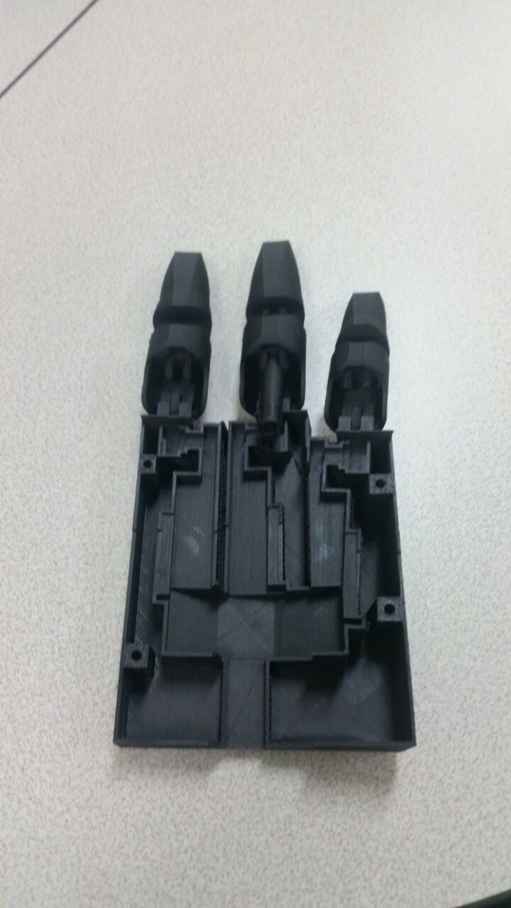
These designs also includes a shot to try to make a functional electrical rotating tumb and gave us a lot of feed back.And it came up something like this.
![]()
Mid print we stop it and reiterated because the mechanical part was working. So now we had to make it pretty.![]()
-
Adding the falanges
09/02/2016 at 17:19 • 0 commentsNow that we have our custom linear actuator made, we have to move something. The thing with the falange is that we have to actuate it from one point and leave it anchored from another. So if we imagine our actuator as our plane of reference, the falange is going to be another plane so if we move a straight line from our LINEAR actuator that passes trough a rotating plane, its going to make a curve at that plane. So we came up with this.
![]()
Its not pretty but we were moving forward.
So, putting the anchoring point on the actuator and printing it out we proceed to verify our approach.
We got slow but strong movement so great! However we did change the ratio of the motor reductor to have a finger that opens and closes in about a second, if we need to. At this point we began to think about the finishing of the product, remember that the project only succeeds if we can sell it and give it to people that need it. So we thought about the looks of it, the toughness and the lightness. Yeah everyone mind goes for carbon fiber and that its a Technic that we are not ready for financially and time wise. So the next best thing, carbon fiber PLA filament. Its goooood really good stuff. So the next video is with a new linear actuator (with a bottom part, so we don't have to hold it all the time) and a "carbon fiber PLA" (from now on carbon fiber or CF, we know it is not but you we the idea) falange.
-
Building a custom micro-linear actuator
08/30/2016 at 20:43 • 0 commentsSo, as the description of the project says, one of the premises of the product is to avoid using those strings that every other open hardware prosthetic hand uses. Yes, we know that the human body uses tendons but we didn't like having a shaky wobbly hand, hence linear actuators. When you search for a linear actuator that fits five in the palm of the hand, all arrows point to the same direction, Firgelli Automations. They are great, not that expensive but... and a big but if you only want to use one battery, they use 12V and where is the fun in buying everything.
So that's why we decided to make our owns. Hasn't been easy.
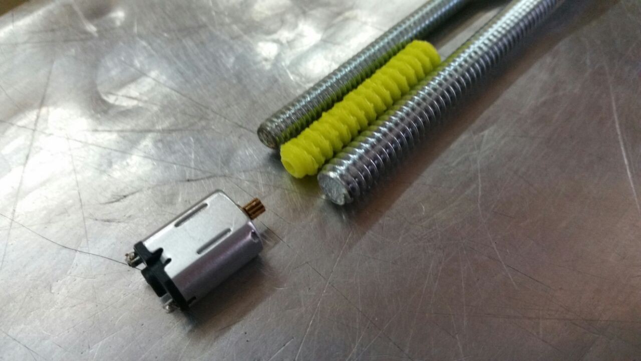
So, we started by defining the screw where it would glide. The big question was.... and store bought endless screw or a 3D-printed one.
![]()
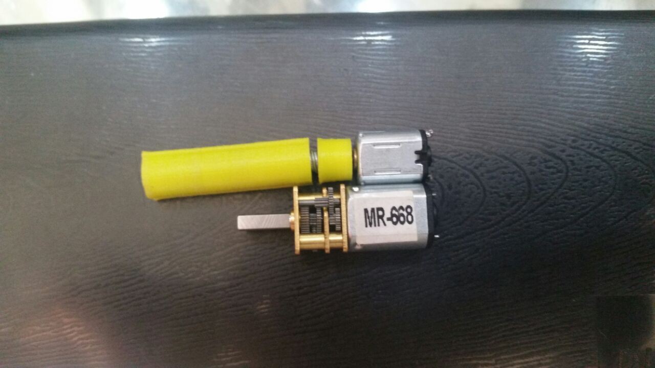
The store bought one implies a 3D-printed adapter and the motor shown there was too weak and too fast also a geared motor with an adapter would be just too long, as shown in the next picture.
![]()
To control the DC motor we tried to use a shield with H-bridges to move it forward and backwards. But, tree things, one is that all the shields from Adafruit (Where we buy literally everything) for DC motors require 12V auxiliary power and no. Second is that its bulky and space is not a given. Third how do we know whats the position of each finger. So, we decided to take apart a servo and use de encoder as our controller and the potencio-meter as our sensor. Yes pretty crafty.
So for the "end" result of our custom actuator there is the video at the end.
TNS 1i
The idea is to create an accesible prosthetic hand that is commercially available in Colombia and doesn't use the classic string system.