 Yann Guidon / YGDES
The critical part of the "bitslice" architecture defined by #AMBAP: A Modest Bitslice Architecture Proposal is the register set. It uses quite a lot of parts ! An 8-registers implementation with 16 bits each requires 128 bits of storage ! So that's a critical part to optimise, for all kinds of good reasons: parts count, power draw, cost, space and of course : speed...
So what's the smallest bit-storage element ? The R/S flip-flop requires 2 storage elements and 2 "upset" or "override" transistors. A 128-bits set requires 512 transistors... yet it could be worse. And I don't even count the "interface"/buffer transistors (that's 640 now).
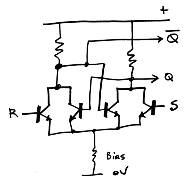
That's only 5 transistors instead of the more complex structures (such as the flip-flop implemented by Dieter)
But I can't really afford 9×128=1152 transistors. Well, I could but if I could avoid it...
Because the latch is only one element : we have the write select and the two read select circuits !
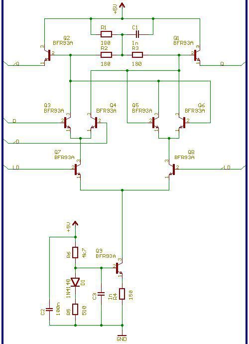
The write select needs one transistor to drive the set line and another to drive the reset line, that's 6 transistors (plus the output buffer). This is now somewhat equivalent to Dieter's circuit (with only one output buffer transistor).
However Dieter's circuit is fully differential and requires two differential inputs, or 4 wires, which also increases the number of driving transistors. The differential LD signal might be the hardest part because the D input is a simple value that can be "faned out". The clock signal however must be steered to the appropriate register (let's say one of the 8 registers). For the simpler R/S flipflop, I think I have found a simpler method: it's unipolar and uses less transistors (again, buffer transistors are omitted):
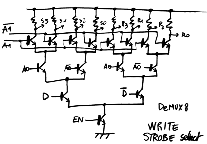
This is another conjunction between my relay musings and Dieter's experiments (who coined the relay/ECL equivalence for decoders)
The D and /D inputs could be coming from a previous flip-flop, or even merged with the buffer outputs (I should check this and the voltage levels might be incompatible but hey... maybe complementary transistors could help here ?)
The cool thing is the EN input : the A0-A1 inputs can take some time to settle (and ripple down the fanout amplifier circuits) and a single EN strobe will then propagate to only one output. The EN signal can come from the same signal that drives /LD of Dieter's latch.
I'm OK to sacrifice a bit of speed in order to save transistors and I'm not sure this circuit runs as fast as a NOR3-only D-ECL circuit but I got fast transistors so what. Furthermore, this circuit seems to work as well for Silicon transistors :-) (it's only a matter of setting the correct bias currents and voltages)
Parts count for the writer tree : 2 or 3 transistors per latch, depending on the necessity of a buffer. Maybe mixed PNP and NPN could be used to save more parts.
The tree could be "cut" to reduce its height (in case it causes problems). Since 8×2=16 outputs are required, a 2-level system (with two 2->4 decoders) could be used... I'll see later.
The read MUX tree reuses the same "unipolar" ideas, though NOR3s and NOR4s can also work nicely.
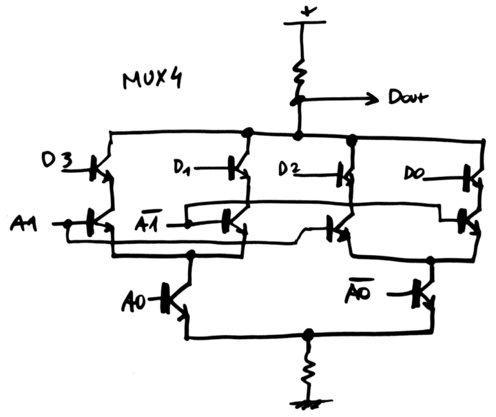
Now, you can't deny that this circuit is pretty compact: it uses less transistors than NORx circuits and I'm ready to accept that it's not as fast as plain D-ECL.
Cost for a tree: 3 transistors per latch. Total per bit : 3 for write, 5 for latch, 6 for read. That's 16 transistors per bit, or 2048 transistors (at least) for a 8×16 register set... and I didn't count the input/driver latch. This amounts to most of my stock of AF240...
Discussions
Become a Hackaday.io Member
Create an account to leave a comment. Already have an account? Log In.