Close
0%
0%

SS Minnow - 8-bit Game Console

Building an 8-bit game console based off of the 6502 and an ATMega 162 (for advanced I/O) .

Similar projects worth following
I've decided to take a plunge and try to build my own gaming console. The 6502 is special to me, so that's the heart of it - but I'm using some ATmegas for more modern stuff: serial I/O, Internet?, Video out, etc.

Fair Warning: I'm not a HW guy, I'm a life long systems/graphics/tech programmer. I was hesitant to post this because I'm sure I'll be doing countless things wrong - but I learn a lot from others' successes and failures, so maybe this will be of interest to someone!

Ever since playing the Intellivision and the NES I've always wanted to build my own console, it's time to full fill that dream!

It's called the SS Minnow, here are the part code names and descriptions:

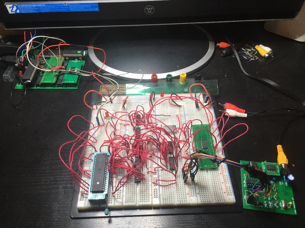
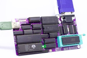
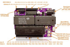
The SS Minnow will consist of a motherboard and a graphic's board.  The motherboard is called The Island.  

The Island will consist of Gilligan (6502 CPU) for handling game code and the Professor (ATMega 162v) which will be the utility chip.  Gilligan will execute the cartridge code as well as update a display list on the graphic's board.  The Professor will be the motherboard work horse handling things such as serial i/o, peripheral i/o, SPI stuff (maybe?), etc. 

Gilligan can access 32 KB of RAM, and the Professor and Gilligan share a 256 bytes of that RAM (physical address 0x0200, 0x02ff) for back and forth packet communication.

The Professor has Internal RAM and additional items will be hooked up to his pins; currently peripherals and serial i/o, but in the future some SPI expansions might be added.

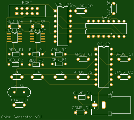
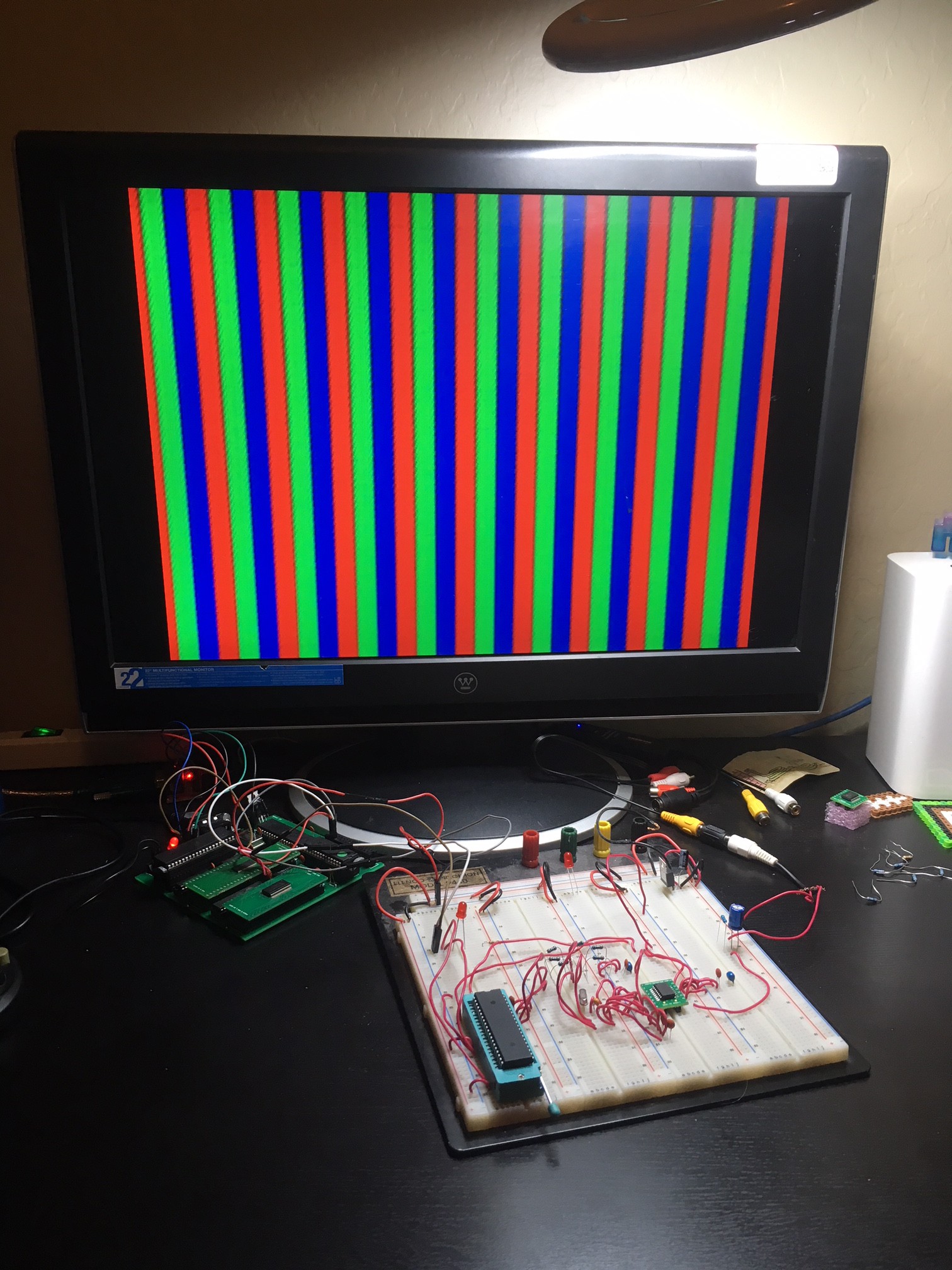
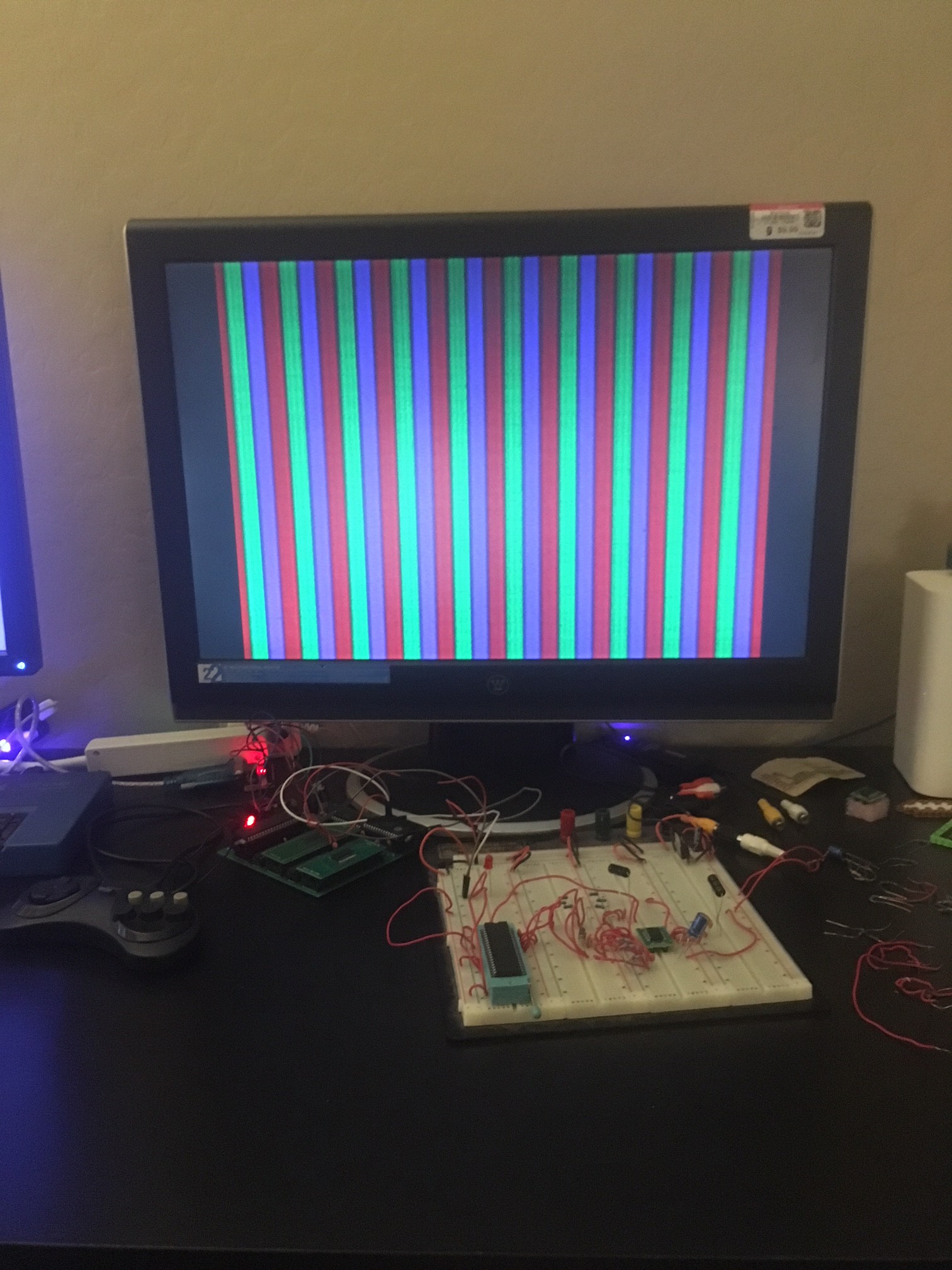
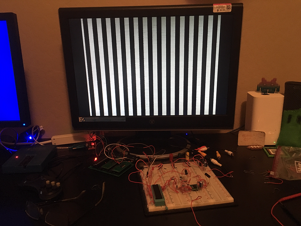
The Island's bus has lines to the graphic's board, the graphic's board is called The Ocean.

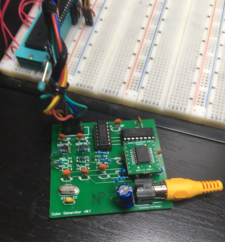
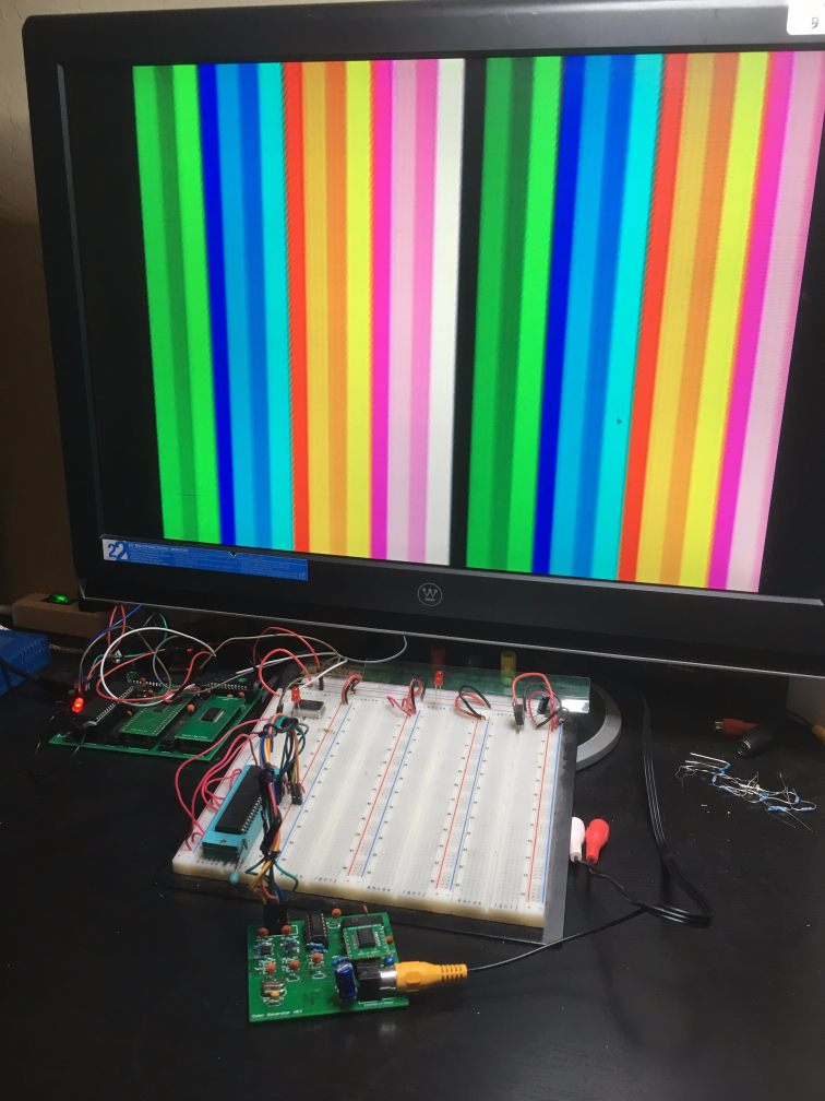
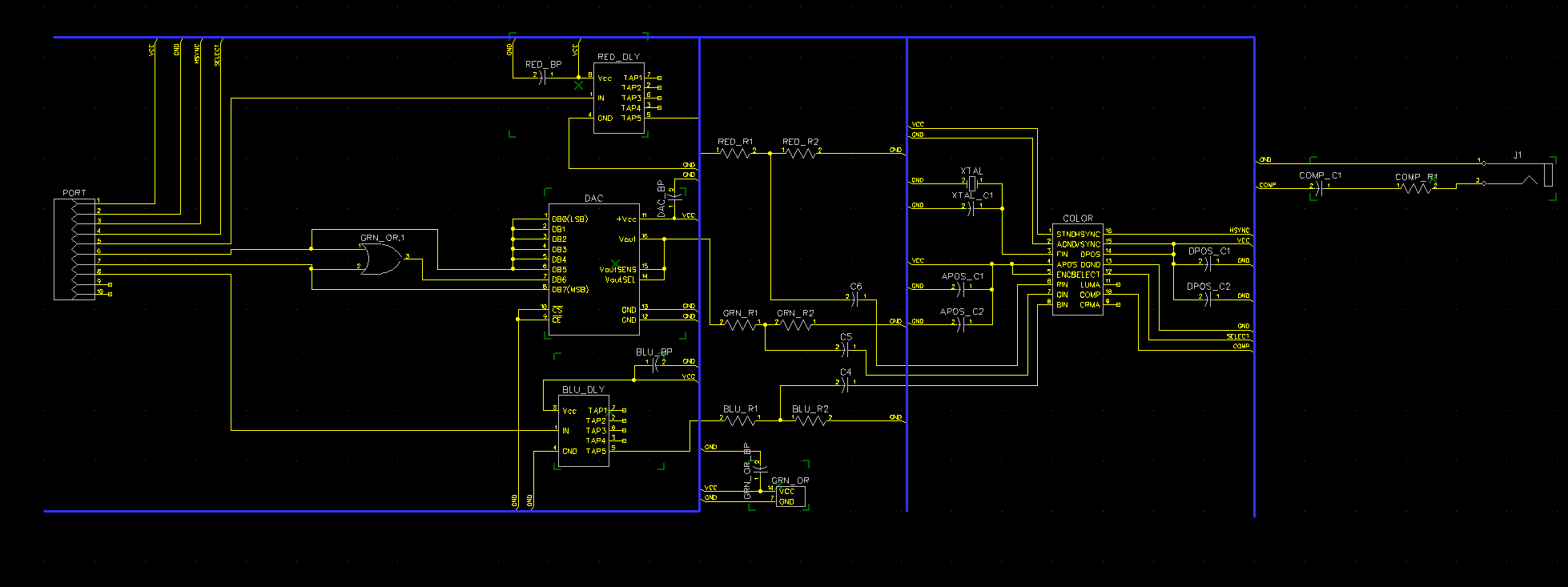
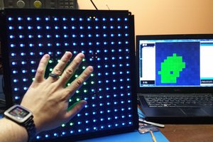
The Ocean will consist of Ginger which will interpret display lists and write scan line buffers to be consumed by Mary Ann for video output.  The current design is for Ginger and Mary Ann to be ATMegas, but the design is still in the schematic stage.

I'm not sure how much or little technical detail I should go in to - more can be found on the github along with all of the code the schematics - I've never done one of these projects before so hopefully I can find the right technical balance as I move forward.

View all 7 components

  • Per pixel color update

    trapper.mcferron09/20/2018 at 06:07 0 comments

    Well I'm on the next stage of the project... hooking up hardware so it'll update color at a per pixel frequency instead of per tile.  My 8Mhz clock speed is too slow to update per pixel; so instead my plan is to preload the tile's color bits into shift registers and have the shift registers spit out the on or off bits each pixel.  While they're spitting them out, I'll have a second set of shift registers I'm preloading the next tile color bits into, and so on... basically double buffering per pixel tile data through shift registers.

    So I'm starting simple by using only 2 shift registers - which will allow me to output a single on or off bit for each pixel.  Ideally this works and gives me per pixel white or black (on or off), once it works I can expand it to the 8 shift registers I need (4 bit color and double buffered) and have my full 4 bit color per pixel.

    Here's the breadboard...

    Looks kind of messy, but the concept is simple - you can find the schematic under my github at:

    https://github.com/mcferront/ss_minnow/blob/master/PCB/MaryAnn_1bit.dch

    It's not worth posting more right now because... well nothing works.  It's not even responding back to The Island (my motherboard).  I'll start debugging tomorrow, basically by hooking up LEDs and try and figure out where it's freezing.

  • Color Generator PCB Works!

    trapper.mcferron08/31/2018 at 16:12 0 comments

    Wow - so I didn't expect my PCB to work.. but low and behold it does!   I'm not great at soldering (but I guess I'm getting better) and I had to solder two SMT chips to the board along with the usual through hole.  It was almost a disaster multiple times, but due to persistence and solder wick I was able to do it successfully!

    Even with everything soldered I was still convinced I probably missed a required rat line or something.. but I plugged it all in and boom!  I had my color bars.. with the added bonus of almost all of the interference is gone;  isolating these higher frequency parts to their own PCB really helped.

    So, to recap; my new color generator pcb takes 8 pins: Red, Blue, Green High, Green Low, HSYNC, Select, Vcc, and Gnd.  It then converts everything to a color composite signal and outputs via an RCA composite jack.  Here is the board in all its soldered glory...

    And here it is working:

    To recap:

    The mother board (aka The Island) is in the back left with the red light, that is sending the 8mhz clock signal to the chip on the breadboard (aka Mary Ann) (In the future it will send the full address/data bus etc.).  Mary Ann then uses the 8mhz clock signal to generate RGB colors and an HSYNC signal and sends them to the color generator board.  Every VSYNC Mary Ann sends an interrupt back to The Island so The Island knows when a vertical blank occurred and, in the future, it will be uploading an updated tile set each frame.

    My next step is to change colors per pixel instead of every 8 pixels (8 pixels is the width of a tile, which is what the color bars are representing).  8mhz isn't fast enough to do this all on the Mary Ann chip so I'm going to be using a combination of HW such as shift registers to pump out the per pixel colors - I'll go into details and a schematic on my next post.

    This is very exciting!

  • Ordered Color Generator PCB

    trapper.mcferron08/23/2018 at 06:11 0 comments

    Quick status update - to help reduce the interference I needed to move the delay lines and the color generator chip (AD724) to their own board.

    I attempted to do this and solder them all in, but it quickly became a mess of wires... partly because it's a bit complicated, but mostly because I'm a novice at this stuff.

    So - I decided to get a PCB made, this will contain the delay lines, color generator chip, and all of the resistors and capacitors needed.  Essentially it will take the following inputs:  Vcc, Gnd, HSync, red, green high, green low, and blue.  It will then output a composite signal via an RCA jack.

    This way the color composite signal will just be "done" and I won't have to worry about messing it up or making extra breadboard room when I move on to the next phase, which is wiring up a circuit to do the per pixel tile rendering... more on that later.

    I uploaded the gerber files and the schematic to github, but here's a quick pic if you're interested:

    And here's a pic of what the PCB should be like

    So...we'll see...hopefully this works as expected.  This phase has been slow going but good, I've learned a lot about chip/signal delays and interference. 


    I'm excited to move on to the per pixel rendering!

  • Fixed the Color Bar Bleeding

    trapper.mcferron08/12/2018 at 19:21 0 comments

    Wow it's been about a month since my last post.  I was away for a few weeks so I didn't have chance to work on it.  But now, I've fixed the issue!  

    My hypothesis was correct, however the delay was longer than 200ns, it was more like 500ns - I had a good friend help walk me through the datasheet to fully understand this.  He recommend I order delay line chips - I did just that, I ordered 2 of these (one for the red bit, one for the blue) - Maxim Integrated DS1100.

    Unfortunately they only come as SMTs and I need DIPs for the breadboard.  In the past I've used protoadvantage.com to solder a SMT->DIP connector for me - but it's quite expensive - so I decided to try myself.  Fortunately Schmartboard offers these pretty great SMT->DIP boards with the solder built in, so you just have to heat it up and it binds to the chip:

    https://www.youtube.com/watch?v=-32orELxkpE

    I ordered two of these - and wow I actually did it on the first try!!!!  Here's a pic:

    Then - after some trial and error, I hooked it all up and boom! The red and blue color timings are the  same as the green - and there is no color bar bleeding!

    There is still some minor interference, they aren't as crisp as I like.  This seems to be a result of the delay lines - I need to play around with my capacitors and see what's going on - unfortunately this week I can't get to it, so hopefully next week I'll post an update.

    After I fix the interference the next step will to be to draw per pixel detail on the tiles instead of color bars - this will require quite a few hardware additions to meet the required timing, I'll post some details on that as I'm getting started.

    I just noticed I had another follower!  Wow you guys are great - I'm glad there is some interest in watching me stumble blindly through this :)

  • 16 Color Palette

    trapper.mcferron07/06/2018 at 05:39 0 comments

    So the DAC (AD7302) I ordered arrived - but it turns out digikey sent me the wrong chip :(  It was in the correct packaging - but it was actually an ILD55.  So that was unfortunate, I contacted customer support and I'm still waiting for a reply.

    Meanwhile, I found a different DAC on Amazon with free (Prime) shipping, so I went ahead and ordered it: AD558.  It came today so I wired it up.

    And boom! Now I have my 16 unique color bars!  These are 4 bit color in the form of R, G_HI, G_LO, B

    The green color goes through the DAC so I can convert it to 3 unique voltage levels.  Unfortunately where those voltage levels shift there is some bleeding.  You can see it in the pic after the first 3 green bars, it goes to light blue just before dark blue.  As best as I can tell, the DAC can take 200ns to shift voltage levels, This equates to 0.2uS - and the pins coming straight from my ATMega take only .125uS - I believe this is a large enough discrepancy to account for the brief bleeding. 

    So... now I need to think about this and do some research.... I'll post back when I come up with something!

  • (Minor) Color Bar Update

    trapper.mcferron06/29/2018 at 06:12 0 comments

    It was bugging me today that the color bars were a bit muted - not as vibrant as I would expect; it became really obvious when the colors transition - it almost appears to drop to black.


    After a bunch of testing and re-examining the board I realized that I used some 750ohm resistors instead of 75ohm - so it dropped the voltage level much below what I expected... I know I tested the voltage levels before... but.. somewhere along the lines of my intense 2 week debugging and refactoring I must have made a mistake. 

    So now the colors are as vibrant as I'd expect!

    The only issue is some minor noise where the colors change... I haven't been able to track this down yet but I'm sure it's related to capacitors or resistors - I'll keep an eye out for it as I wait for my DAC for full 4bit color :)

  • Color Bars!!!

    trapper.mcferron06/28/2018 at 06:48 0 comments

    Well today I received my new AD724 chip, theoretically all I had to do was plug it in and replace the one I had blown and I'd have color bars... or cry salty tears because if it didn't work then I would have no clue what was going on, so I plugged it in and turned on the power!...

    Nothing worked - blue screen (blue meaning the monitor had nothing to sync to).


    So frustrating!!!!!   I spent a long while pouring over the datasheet for the hundredth time... I had everything hooked up right... why was I seeing nothing? No wavy bars, no noise, just... nothing.

    So I looked things over one more time... I noticed the capacitors to the color input pins were hooked up wrong.  They were supposed to be hooked up in series... but I actually wired them in to the breadboard in such a way that they would have no effect.  I dunno, I was probably tired and those holes are so tiny they always just look correct... embarrassing I know.  But these were just for the color inputs - theoretically I should have AT LEAST been seeing black and not a blue no-sync screen right?  But... you know, desperation and all...so I wired them up correctly and turned on the power...

    OMG IT WORKED I SEE COLOR BARS!!!!!!

    I actually thew off my headphones and screamed to my wife "oh my gosh - color bars!!!!!!"

    The bars are R,G,B - the next step is to get a DAC and use it to vary voltage signals to the color pins so I can send my 4-bit color palette: R, GG, B - hopefully the next screenshot I post is 16 different colors instead of just red, green blue.

    An interested reader here will wonder, well was the original AD724 blown or was it incorrect capacitor hook ups all along?   I wondered that my self so I put the original chip back in and boom - it worked perfectly.  Ah well - now I have a back up :)

    Next step is to order the DAC, hook it up, and modify the code to do 16 color bars.  I'll post when I have an update, hopefully this weekend or next week!

  • VSYNC Progress! But Color Woes :(

    trapper.mcferron06/23/2018 at 05:27 0 comments

    Wow it's been 2 weeks since my last update, that's because I've not had much to report - even though I've been working my tail off on this... seriously - like 5 or 6 hours of sleep a night, that catches up with me after awhile :(


    So - here's the deal; I got the AD724 all hooked up and I was super excited to test my code and the HSYNC timings - I plugged it all in and..... basically just a flickering monitor with nothing really to show.


    So I poured over my ASM code for a long time, found lots of small timing bugs (this NTSC timing has to be pretty perfect) and tested... didn't work so I repeated the progress over and over again.

    Speaking of NTSC timings - OMG there are sooooo many different references and they all very slightly!  For example; if you're trying to figure out timings for sync pulses, visible scan lines, front porch, back porch, etc.  most of the documents vary slightly - here are some examples of ones which are different:

    https://bradsprojects.com/generating-video-signals-with-a-microcontroller/

    https://people.ece.cornell.edu/land/courses/ece4760/FinalProjects/f2014/jn286_cy255/jn286_cy255/index.html

    https://people.ece.cornell.edu/land/courses/ece4760/FinalProjects/s2006/kwj5_mhw23/index.html

    http://www.sxlist.com/techref/io/video/ntsc.htm

    https://www.maximintegrated.com/en/app-notes/index.mvp/id/734

    ... I could go on...

    But this lead me to the conclusion that televisions (and monitors) can be a bit forgiving (but not too much)... so why was mine showing nothing???

    I decided to try ditching the color chip (AD724) and directly sending voltage signals (gray scale) to the monitor... after a few quirks in my timing I was able to get it to look good on two displays... my Goodwill monitor and my USB->Composite capture software... here are the bars:

    Hooray!!!  That was an exciting moment - taken at 2:30am when I had to be up for work at 8:00am... totally worth it though :)

    So now that I had the sync working on two monitors I decided to revisit the color chip... absolutely nothing was coming out of it - so I started pouring over the datasheet again.

    http://www.analog.com/media/en/technical-documentation/data-sheets/AD724.pdf

    To my horror I realized a minor issue.. the color input pins (RIN, GIN, BIN) maximum input values are 714mV.  I never realized this - I had been blasting them with TTL 5V levels!    I consulted my HW mentor and asked if I could have blown the chip... his response: "Totally".   So!  That's ok - I've got everything wired up to send the correct voltage levels and I just digikey'd off for a new AD724.  As soon as it gets here I'll plug it in and see what happens!  It should be here next week, so hopefully I'll update this within a week.

    Thanks for reading!  This is the most challenging and most rewarding project I've ever attempted :)

  • My Goodwill Hunt (Part 2) and More!

    trapper.mcferron06/09/2018 at 07:21 0 comments

    I had an old composite to USB converter lying around and the software for it - so I got that all installed (along with its VHS Screen Grabber software) and working as a place holder until I found a monitor which accepts composite.

    Then I wired the graphics board (The Ocean) up to  the motherboard (The Island).. and powered it all on!!!

    Sadly, The Island freaked out; it wouldn't spit out it's normal debug text and the debug LED wasn't blinking at 30hz.  After an hour or so of debugging I realized the problem, but to make it clear I need to back up a step....

    The Island (motherboard) communicates with The Ocean (gfx board) through a 30 pin connector.  This has the 8mhz clock, address bus, data bus, VCC, GND, and a VSYNC pin used for The Ocean to tell The Island when it VSYNCs.

    I'm not using the address or data bus right now, but I wired up VCC, GND, 8mhz clock, and VSYNC...  it turns out I screwed up my PCB design and VSYNC on the 30 pin connector is actually wired to the 8mhz clock!   Ugh how dumb - I'm not sure how I missed that...but that's why The Island was freaking out.

    Fortunately I have an additional VSYNC debug pin on The Island, so I used that and bypassed the broken VSYNC on the 30 pin connector.

    Then I powered it up again... BOOM The Island started up as normal and spewed its debug information to the serial port on my PC.  Unfortunately The Ocean composite output just kinda flickered on my Screen Grabber software. 

    After debugging for awhile, I pulled up the datasheet for the AD724 (that's my color generator for the composite output).  To my horror I realized that, for some odd reason, I ignored the important parts of the chip.  I didn't add the correct resistors or capacitors, and I was sending voltage levels MUCH TOO HIGH to the R,G,B input pins.  It wants a max voltage level of 357mV - I was sending it a full 5V!!!!   Oh man I hope I didn't blow the chip :(

    So.. I didn't have the necessary resistors and capacitors here - which meant I went to Amazon and ordered everything I need.  It should be here tomorrow (Saturday) and I'll hook it all up to test again.  I pray I didn't damage the AD724 because it was about $40 (it's a SMT and I had to have it soldered to a DIP breakout board).


    As I wait - I have other exciting news...I took another trip to Goodwill tonight and there was a new monitor (well, new to Goodwill).. a Westinghouse with composite input and a normal 3 prong power plug!!!!   I picked that sucker up for $10 - and now I'm good to go!!!

    Here's a pic of the beauty, price tag still on...

    Anyway - I'll need some peace and quiet to hook the resistors and capacitors up (I have to do a voltage divider network to get down to .3v) - so I'm not sure I'll have that chance over the weekend - but I'll post back here when I have some results, hopefully Monday or Tuesday night at the latest.

  • My Goodwill Hunt!

    trapper.mcferron06/06/2018 at 15:51 0 comments

    I realized I don't have a monitor which will take composite input!   The only TVs we have in the house which take it are much too big for my workstation - so on to Goodwill!!!   That's what I did last night and here is a quick recap of my adventure - feel free to skip this entry entirely it has no technical details relevant to my project.

    So I went to Goodwill last night to get myself a monitor with composite input.  They had a whole rack of old monitors Dell, Gateway, Acer, you name it!  

    Guess what I found out about old monitors?  Most of them only have a VGA input!  I figured they would all include composite... I'm not sure why, I guess because my old one did.  Anyway so I found 1 that had composite input - I was super excited!  Then I realized it had a custom power plug instead of the standard 3 hole one... ugh of course it did.

    So I went on a search through every power supply I could find in Goodwill, nothing provided the 3.5 amps needed by this thing :(

    I decided to switch gears and try to find an old small TV, oddly enough they have very few.  After much searching I found an old LCD panel that you'd strap to the back of a car seat so your kids can watch a movie.  It used a miniplug input for A/V composite.. but no big deal I have one at home.  It took awhile to find a matching power supply but I found one and tested it out - the screen lit up so I was good go!

    My quick 5 minute 8:00pm Goodwill trip ended up taking almost an hour as my patient wife roamed the asiles with our tired 6 year old...but...totally worth it!

    So after getting home I figured I should test this sucker first...I found my miniplug A/V cord only to realize it wasn't an A/V cord it was just audio... it only had 3 rings on the miniplug not 4 :(

    By now it's like 10pm, so naturally I decided to tear through the house trying to find any miniplug with 4 rings, when I was just about to give up I finally found one - old earbuds with a mic on the cord... I figured I could strip it, wire the video signal to whichever of the 4 rings was the video one and it would work.

    After some quick Internet searching I found out that there is no standard (of course there is not) but generally the video is on ring 2.  I stripped the wire and... omg the wires were so tiny and full of this fabric stuff and so twisted together that everytime I tried to separate them and wire my composite wire to it it ended up in this jumbled disaster.  I know that sounds strange, I should have taken a picture, but I've never seen wiring like that (it must be a technique they use to keep the overall cord size super small).

    The only course of action was to rip it apart and extract the mini plug itself and resolder my composite wire directly to the internal connection that is linked to ring 2.  It came apart fairly easily and my trusty mulitimeter quickly showed me which internal connection to solder to.  I'm a pretty poor solderer but after some trial and error I did a decent job.

    So I went to test!  It was a very exciting moment for me to have made my own adapter.  I plugged the RCA composite end into our old dvd player and the miniplug into this custom lcd panel and boom!  Buzzing and no video :(

    It turns out that this thing didn't use the common choice of ring 2 for video, it used it for audio.  So... after a bit more testing and trial and error I determined it used ring 4 for video.. no problem I'll send it to ring 4.  After some rewire I was ready to test!  Now no buzzing... but the video just did a quick white flash and nothing.  I played around with it for a bit longer and came to the conclusion that either A: it doesn't take a composite input, it does say "slave device" perhaps some other master unit is sending it a custom signal.  or B: it's just broken, afterall it was thrown on a rack in Goodwill.

    It was now 4 1/2 hours later, 12:30am - and I was back to...

    Read more »

View all 23 project logs

Enjoy this project?

Share

Discussions

Scott Prive wrote 08/24/2018 at 00:09 point

You may have seen this, but just in case here's a "hardware refresh" of an Atari 8-bit. You'll notice it uses submodules (other hardware projects) to solve specific problems or to extend the platform.  Interesting project - following! 

https://ataribits.weebly.com/1088xel.html

  Are you sure? yes | no

trapper.mcferron wrote 08/24/2018 at 22:48 point

Wow I hadn't seen that - that is absolutely awesome, thanks for sharing!  My main goal is to learn how to do all of these submodules myself - it's been a fun learning exercise even if my solutions are sub-par :)

  Are you sure? yes | no

Similar Projects

Does this project spark your interest?

Become a member to follow this project and never miss any updates