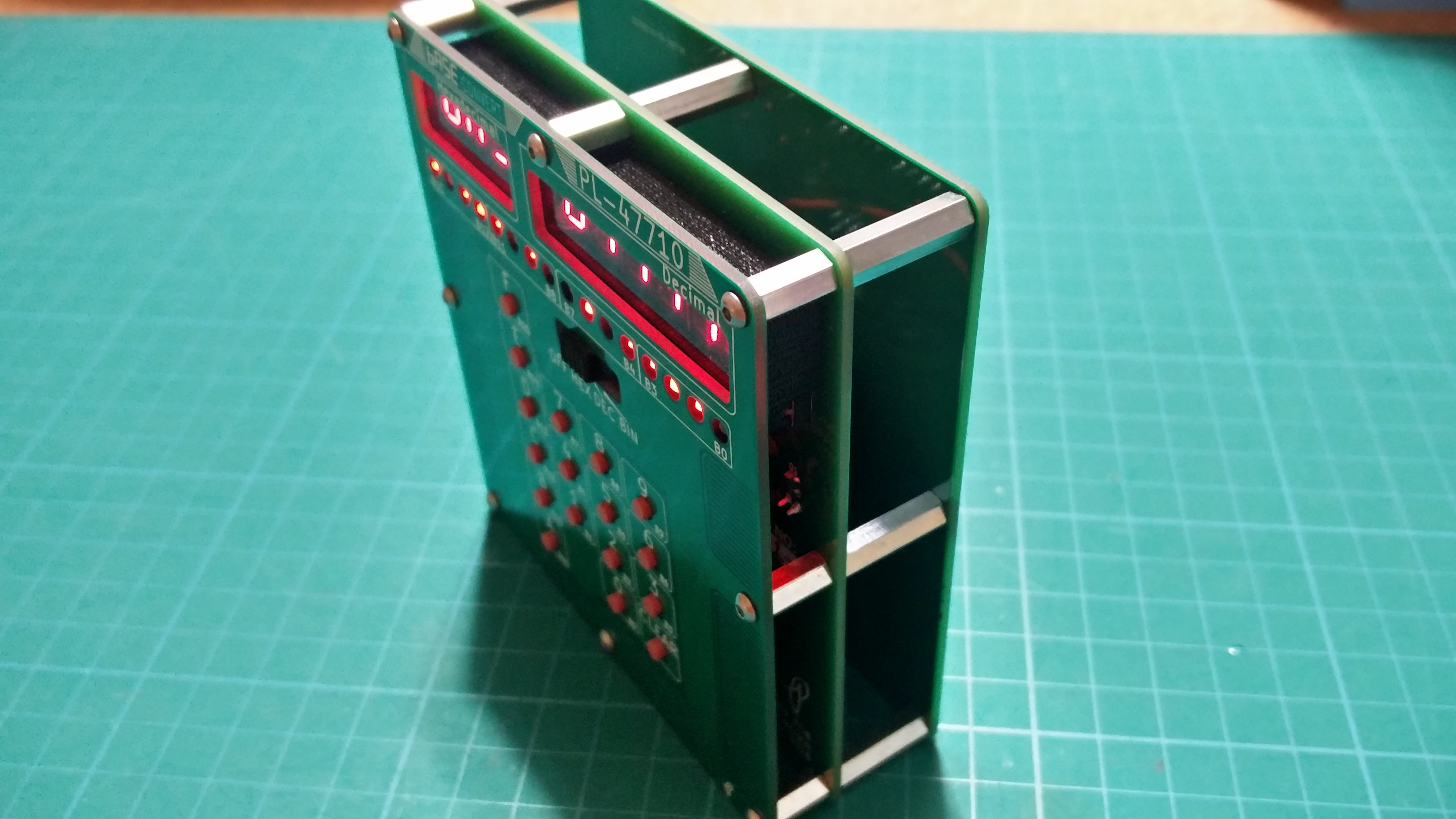
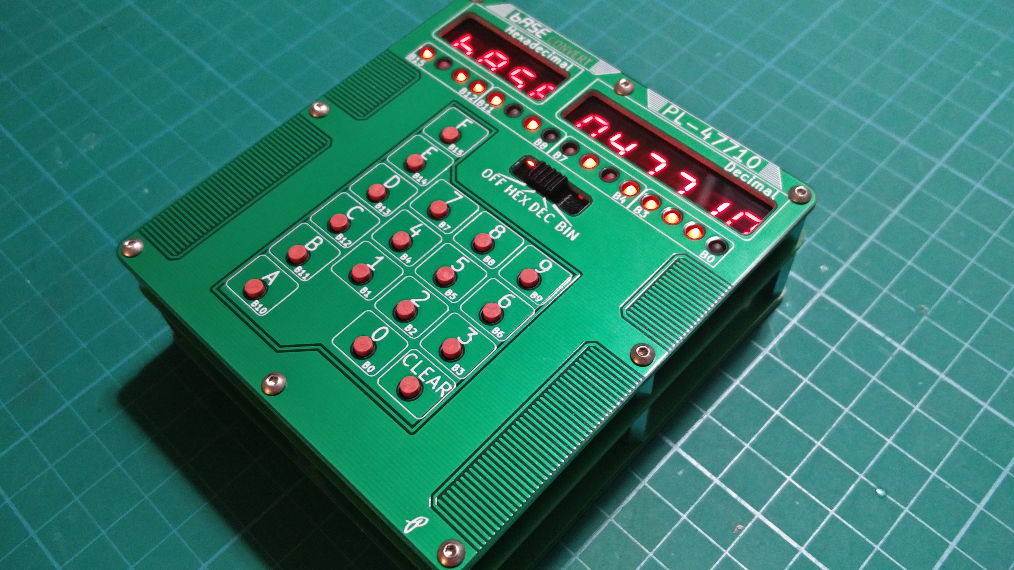
After having to wait for resistor arrays since I placed the wrong footprint size on the main PCB I have finally fully assembled a Rev A.


I did run into a few quick fixes such as things I should add to the silkscreen. I also found out after much frustration that there needs to be a 1k resistor on each PNP transistor between the base and emitter otherwise 3.3V is not enough to turn off the display. I hand corrected the above but issues with the 3.3V LDO are making me consider scraping running from 4xAA anyways and sticking with 2xAA or possibly a LiPo for Rev B. I found that the voltage from the LDO is 4.1V and I suspect it has to do with adding the 1k resistor to the PNPs. I have enough to assemble 5 more so the next one will use 2xAA and skip the LDO, I will have to see if the display is bright enough.
Anyways it is nice to be able to hold the real thing instead of staring at a render in FreeCAD.
 leumasyerrp
Discussions
Become a Hackaday.io Member
Create an account to leave a comment. Already have an account? Log In.
> I also found out after much frustration that there needs to be a 1k resistor on each PNP transistor between the base and emitter otherwise 3.3V is not enough to turn off the display.
Look into "Digital Transistor" e.g. http://www.onsemi.com/PowerSolutions/product.do?id=MUN2111
It has resistors built-in and footprint compatible with regular transistors. i.e. save you a board spin. There are different values of these resistors. Just need to search for them.
Are you sure? yes | no
Thanks, I will be sure to check it out.
Are you sure? yes | no
Forgot to say: Between the external series resistor that you had and the internal ones, you should be able to make voltage divider of the right ratio.
Are you sure? yes | no
That actually looks awesome. Nice styling.
Are you sure? yes | no
Thanks
Are you sure? yes | no