-
Soldering Begins
06/25/2018 at 10:12 • 0 commentsQuick update - boards arrived, they look good.
I'm starting assembly with just the bare bones - 2 bus switches, enough to select between two inputs. And leaving off all the "just in case" resistors (I'll add them in when things inevitably start acting crazy).
One small problem I found tonight - I selected the wrong package for the shift register. Did I make the mistake when ordering, or when laying out? ... one for the philosophers perhaps.
Getting the hang of my dirt cheap "Bakon" soldering iron with it's knife tip that is poorly tinned...
Will hopefully find a local supplier for the shift register tomorrow.
-
Layout Done
06/08/2018 at 10:23 • 0 commentsA bit of progress to report:
* Design updated to allow any combination of switching between the 4 modules
* Layout complete and sent off to manufacture!
![]()
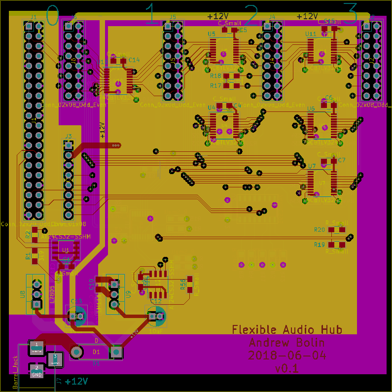
Four layer boards are way more expensive than two layer. I think the design could probably have been done on two layers, but it would have taken me much longer. This layout is nowhere near optimal, and it took me long enough, so the time savings are worth the cash for now.You can't see it in the picture but I put a couple of chips on the back to make routing easier too (side note: is there a way to make changes to the circuit in the layout and then import them back into the schematic? I should look into that...)
Next: start writing some Arduino software to control the switches on the hub, and some Raspberry Pi software to talk to the Arduino. (Yes, the Raspberry Pi could easily do it all but I don't want it to require a pi).
-
Incapacitated Laptop
04/27/2018 at 03:54 • 0 commentsProgress on hold for a while, my laptop has some defective firmware or something and needs to go to the laptop hospital :(
-
Prelminiary Specification
04/22/2018 at 06:17 • 0 commentsI've hacked together something so I can start coding and start shaking out some problems.
https://github.com/andrew-bolin/flexible_audio_hub/blob/master/SPECIFICATION.md
Open for comments, as always :)
-
74-series FTW
04/22/2018 at 01:43 • 0 commentsAfter my frustration with Vivado, I've done a discrete logic implementation of the "MVP".
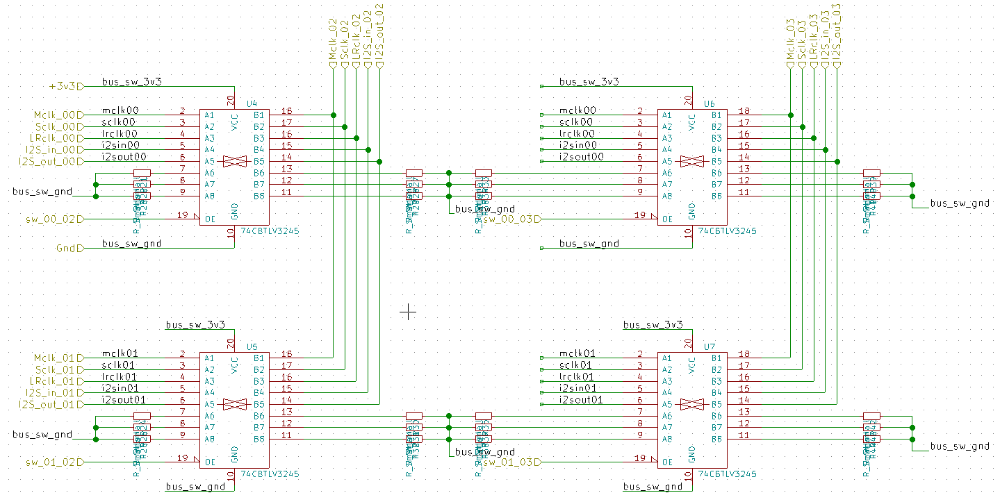
A hub with 4 connections, with 4 switches, so it's essentially 2 inputs and 2 outputs. Each input can be switched to any one output, no output, or both outputs. That's enough flexibility to get some control software started, and plug in some real modules for testing.![]()
Full schematic on github.
Next: layout, ordering parts
-
Vexing Vivado
04/21/2018 at 10:52 • 0 commentsI have a Zynq that is colossal overkill for this task, but I can't get the damn tools to co-operate.
(I want to start with the Zynq because why not)
Vivado (2018.1) on Linux (Ubuntu Gnome) crashes at the drop of a hat. Right click, crash. Hover over a button, crash. I guess it's some bug in its GUI. Any suggestions welcome...
I do have an older Spartan chip but I can't remember how to drive the old Xilinx ISE, maybe I should give Altera or Lattice a go. Or some good old hard wired logic.
For my reference:
# # An unexpected error has occurred (11) # Stack: /opt/Xilinx/Vivado/2018.1/tps/lnx64/jre/lib/amd64/server/libjvm.so(+0x923da9) [0x7f62e7182da9] /opt/Xilinx/Vivado/2018.1/tps/lnx64/jre/lib/amd64/server/libjvm.so(JVM_handle_linux_signal+0xb6) [0x7f62e71893f6] /opt/Xilinx/Vivado/2018.1/tps/lnx64/jre/lib/amd64/server/libjvm.so(+0x9209d3) [0x7f62e717f9d3] /lib/x86_64-linux-gnu/libc.so.6(+0x37140) [0x7f6325935140] /opt/Xilinx/Vivado/2018.1/tps/lnx64/jre/lib/amd64/libawt_xawt.so(+0x42028) [0x7f62c8320028] /opt/Xilinx/Vivado/2018.1/tps/lnx64/jre/lib/amd64/libawt_xawt.so(+0x42288) [0x7f62c8320288] /opt/Xilinx/Vivado/2018.1/tps/lnx64/jre/lib/amd64/libawt_xawt.so(Java_sun_awt_X11_XRobotPeer_getRGBPixelsImpl+0x17c) [0x7f62c831867c] [0x7f62d72224cf] -
Github now open
04/19/2018 at 09:40 • 0 commentsJust uploaded the draft outline schematic to github.
Next step is probably to use an FPGA dev board I have to build up the switching logic and see how much real estate it uses, and connect it up to the Pi (skipping the hub microcontroller and just using the Pi to start with)... -
Starting the Schematic
04/18/2018 at 11:40 • 0 commentsLate. Tired. Been drafting schematic. Will upload to github tomorrow.
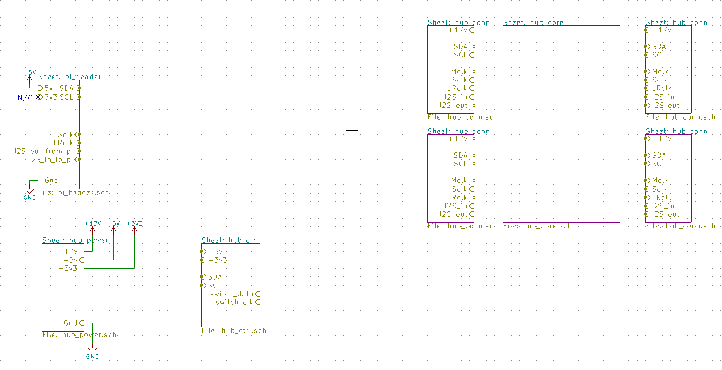
hub core has hierarchical connectors too, I just haven't imported to the main sch
![]()
-
Pi Plug & Play Prioritised
04/17/2018 at 01:04 • 0 commentsSo I realised it would probably be a good marketing / UX decision to make my hub as easy as possible to use with a Raspberry Pi.
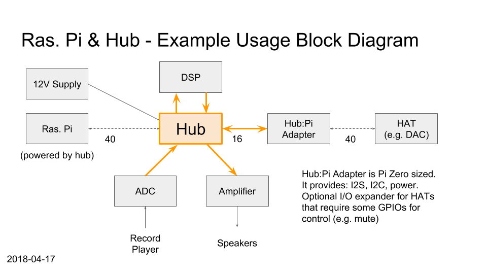
To that end, I'm going to make the Hub essentially a "HAT". The shape & size may not be suitable, but I can easily make it pin compatible, so people can just plug in a 40-pin ribbon cable. The hub will have a 12V power supply and 5V regulator to provide power to the Raspberry.
Now the Pi also has a great variety of DACs, amplifiers, etc available, so I'll make a Hub:Pi adapter to plug these in. Hub connections, for now, are going to be 16 pin (8x2) headers as per FreeDSP. This Hub:Pi adapter will be Pi Zero sized, and carry power (5v & 3v3), I2S audio, I2C for control, and will optionally have an I/O expander for HATs that need some GPIO pins (unless I discover an overwhelmingly standard pin used for mute, these will be unrouted, user to connect jumper wires).I'll try to get some rough PCB renders together soon so this is easier to visualize. For now, here's a block diagram.
![]()
-
Design/Indecision
04/15/2018 at 12:13 • 0 commentsThis weekend has been spent poring over parts catalogs and datasheets.
In the end, I'm more confused than when I started ;)Parts Chosen
- 2x8 header, 2.54mm pitch - as used by FreeDSP. For my first run of boards at least. I'd prefer a more user-friendly connector, but I can use a keyed socket to help a little.
- 74CBTLV3245 - 8 bit bus switch, 75c. Again, a first run quick and dirty choice, in a 2x2 matrix if I can figure out the routing.
- TCA9546A - 4 channel I2C bus switch. Yes, you can do this with a normal bus switch chip, but I want to switch control independently from the audio. This specialty part is worth the $1.75 to have in-band control anyway. (And there's an 8 channel variant for 25c more)
Learnings
- TDM (Time Division Multiplexing) - as well as being an generic term, this is apparently a specific method of transmitting 8 channel audio over only a few wires.
- Bus switches are not that cheap if you want to do crossbar switching.
- This project will end up being be a lot more software than hardware to get the level of user experience I want.
Next Steps
- Check if TDM is commonly supported by DACs & ADCs used in readily available modules (I fear it is not).
- Check if TDM frequencies will be difficult to work with (48k samples/sec, 32 bits, 8 channels... it's too late at night)
- Figure out if a CPLD is practical for a bidirectional crossbar switch, or if the "FP" aspect of FPGA is worth it (the CPLD or FPGA will likely to be under $10 @ qty 1, but the FPGA needs memory etc.)
Open to suggestions of CPLD/FPGA - I have used Xilinx in the past, but I see Altera has a third-party usb programmer for like $2...
Flexible Audio Hub
A very versatile digital audio hub, enabling DIY audio systems using either custom or garden variety modules.
 Andrew Bolin


