 Florian Cliquet
The first specifications were to control 24V relays which control 12V lights bulbs.
With the unused processing power onboard we take also keep the opportunity to generate PWM, with a potential future MOSFET control of lights in mind.
Hardware
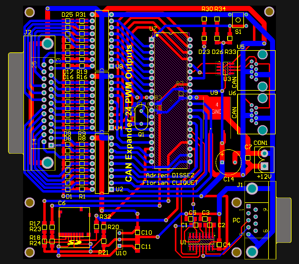
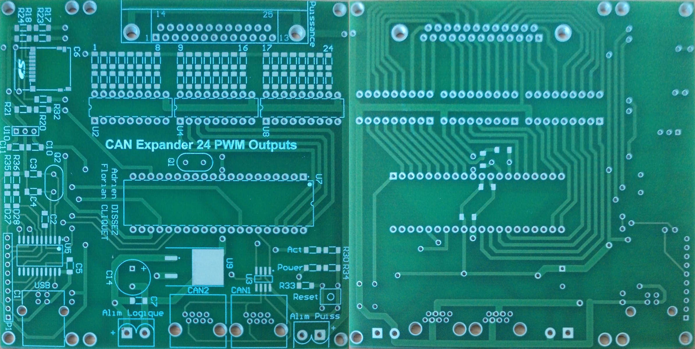
Cards are powered by a PIC18F4680 which generate the 24 PWM by software.
The main purpose was to drive 24V relays so three ULN2803 were used.
The current interface which drove the relays used a parallel port connector (DB25) so I use the same.
It is controlled by a CAN bus, which allow long wires in a very electrically noisy environment.
One of the card have the role of master, it has an SD Card with a text file with CAN Trame encoded on it to control itself and the others. It also have a USB to UART converter to allow a control from a computer.

Schematic
Software
Every microcontroller where programmed with Tiny PIC Bootloader to simplify the software update processus during the development.
The PIC code was write and compiled with PICC.
Light sequences were composed on an Excel sheet then a macro generate the necessary file to put on the SD Card.
Improvement
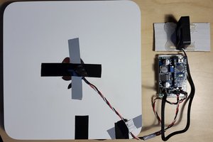
The voltage regulator became a bit hot when all the LED are ON, I only soldered it on 2 boards to do my test. So two solutions, use a switching voltage regulator or not use LED.
 Martin W. Kirst
 Dan Julio
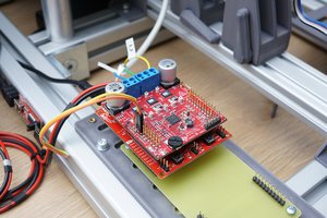
 Benjamin Prescher
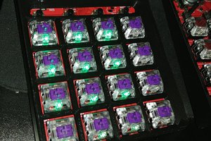
 Thomas