 John Schuch
After quite a bit of development and experimentation, the sensor/transmitter portion of this project is complete. I'm VERY happy to report it has successfully transmitted water consumption data from the meter to my desk.
As you can see in the schematic below, the circuit is not really all that complicated. There are two areas of trickiness. The transmitter / receiver pair that I bought for this project, and the software.
The transmitter and receiver are intended to be use as a wireless serial port link. I had initially thought that would be fine, just sending one character for every water meter tick. After trying that for quite a while what I discovered was that the software overhead to move ASCII characters to the transmitter seriously slowed down the processor in the sensor module. Since I wanted the highest resolution (sample rate) possible from the sensor, that wasn't going to work.
I then found the original manufacturers data sheet for the receiver. While it really has painfully little technical information, I did notice that one of the pins on the receiver was labeled as an analog out (without giving ANY details what the signal actually was!). Well, after playing around with it and my oscilloscope, what I discovered is that the analog output is either some sort of carrier detect signal, or a signal strength indicating signal. Being on deadline for the contest I didn't dig into it very deeply (but I will later). The important point; I found that if I simply sent a pulse to the data input of the transmitter, I'd see a pulse on the analog output of the receiver! Granted, a strange pulse. The analog out floats around 3 volts, and the pulse lifts the signal to about 4.5 volts. While that's a pretty crappy thing to feed into a PIC microcontroller as an interrupt signal, I found that if I capacitively coupled the analog signal to the PIC the spike that got passed was easily sufficient to reliably trigger the interrupt.
Using the transmitter/receiver pair in this way vastly reduced the amount of time it took to send a meter tick to the receiver, and greatly increased the sample rate of the sensor.

The other tricky thing is my auto-calibration routine in the sensor microcontroller.
NOTE: The source code for the Sensor/Transmitter can be found HERE.
The sensor is a three-axis magnetometer, and obviously measures magnet fields in three axes at the same time. What I thought was that if I could have the PIC figure out which of the axes was getting the best (widest span) measurement it could then focus on that axis and ignore the others. This is significant because it means that an end user doesn't have to worry about how their sensor is oriented relative to the water meter.
At power up the microcontroller goes into an auto-calibration mode. I continuously monitors all three axes recording the highest and lowest value for each. It continues doing this until it detects that it has measured at least 5 full revolutions of the water meter. Then, it calculates the span of each axis, determines which had the greatest span, and then only monitors that one axis for normal operation of the sensor.
NOTE: Water must be flowing through the meter for auto-calibration to complete.
To test this, I reset the sensor many times with it in various orientations relative to the water meter. As expected, different orientations resulted in different axes being selected as the primary measurement axis. Nice. :-)
One other thing dawned on me that would would be a problem. My water meter is installed underground. I was planning on installing the transmitter on the same PCB as the sensor and microcontroller. Well, a low-powered RF transmitter isn't going to function very well buried 12" under ground, and under a heavy steel cover plate. Luckily I figured this out before actually assembling the prototype.
I was already planning on having an external box that would contain the battery pack and run power leads down to the sensor. What I finally decided was to locate the transmitter module with the battery pack and use three-conductor cable to connect to the sensor (V+, Gnd, and Signal). An added benefit to this is that since the 3V3 voltage regulator IS located at the sensor, the transmitter is powered directly from the battery voltage. When fully charged, that 6VDC. This should provide much better range for the transmitter.
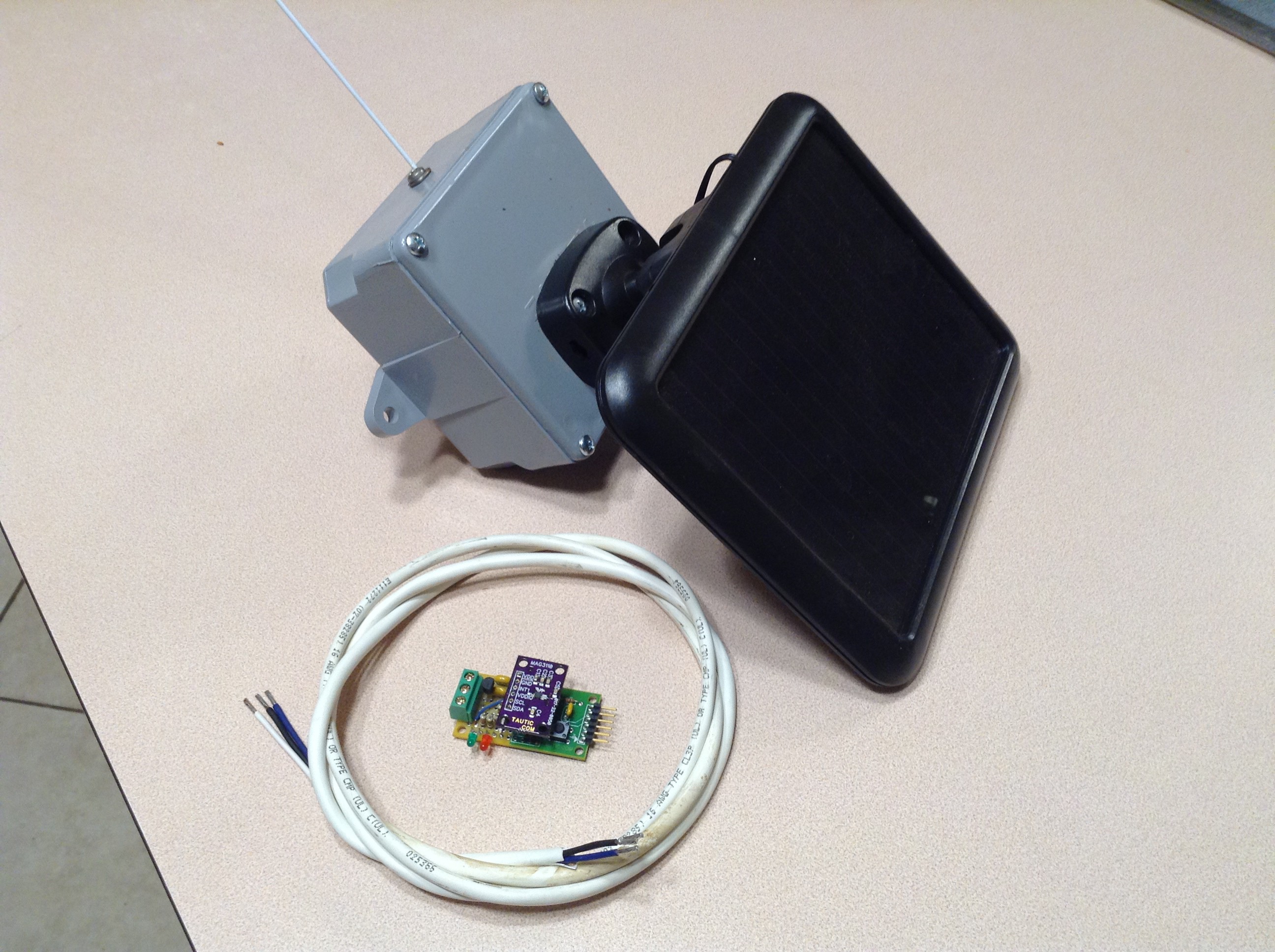
In the above photo you can see the complete sensor/transmitter system. The grey box is a PVC weather tight electrical enclosure (off the shelf from Home Depot). The photovoltaic panel is mounted to the front cover of the box, and has a ball-swivel so that it can be oriented for optimal solar exposure.
Attached to the top of the box is a 13" whip antenna for the transmitter module. Note: The 13" dimension was simply taken from the transmitter data sheet. I suspect that the length could be tuned, or alternative antenna options chosen that would increase the performance of the transmitter. But this worked just fine for me.
In the foreground you can also see the direct-burial cable, and the sensor module that will be installed at the water meter.
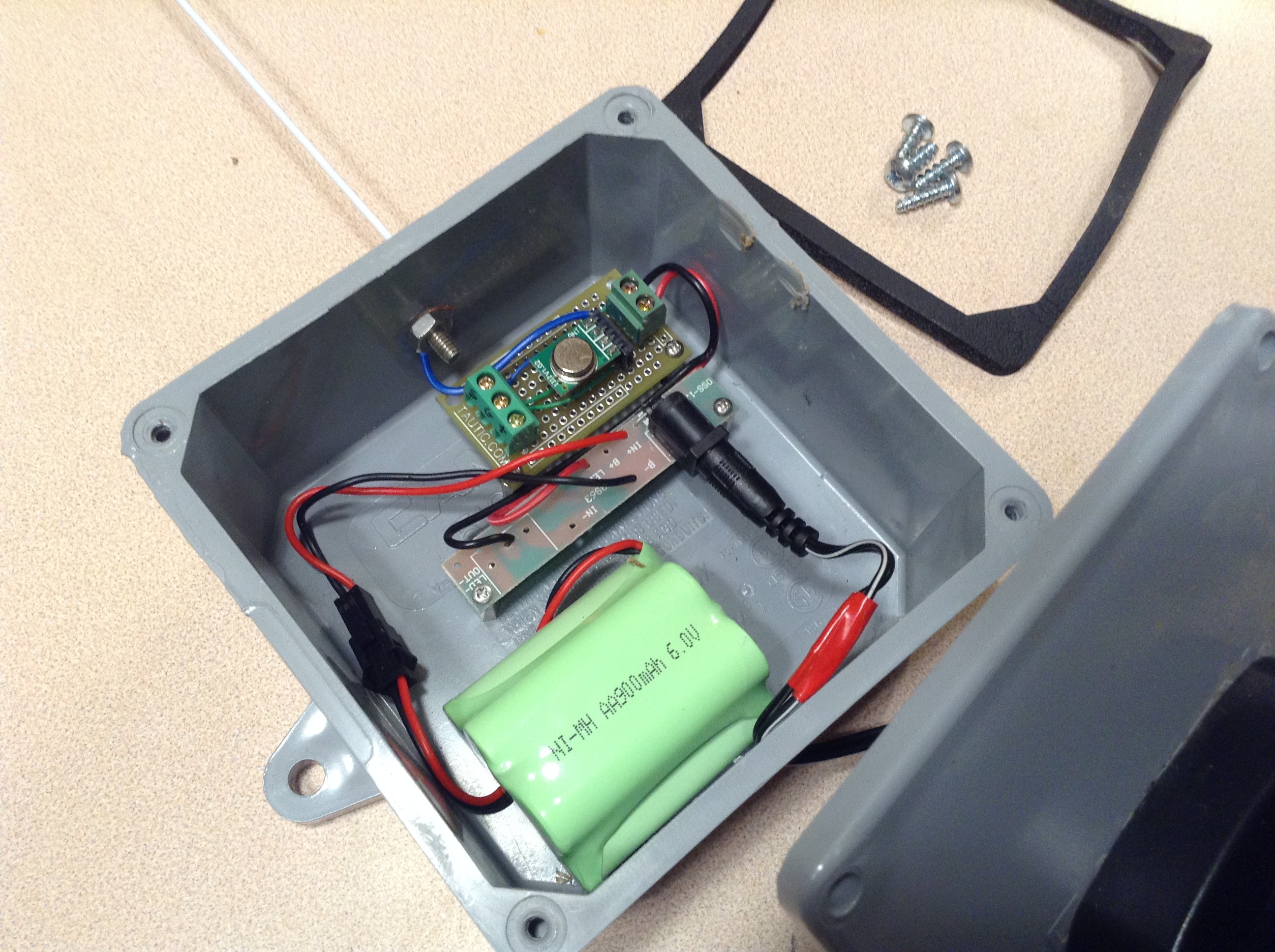
In this picture you can see the inside of the main case.
The wire with the red tape coming in from the bottom is the lead from the photovoltaic panel. It is plugged into the power board. This board contains the blocking diode that prevents the solar panel from draining the battery in the dark. You can see that the large green battery pack is also connected to the board, and there are a pair of power leads connected to the top board. Honestly, this power board was extracted from the solar flood light that was the donor for the panel and battery pack.
The top board contains the transmitter module (the round silver device). Power is supplied to the right end of this board through the two terminals and applied directly to the transmitter module. Power is also routed to two of the three terminals on the left end where the cable to the sensor module will be connected. The third terminal is the data line coming back from the sensor and applied to the transmitter. The blue wire connects the external antenna to the transmitter module.
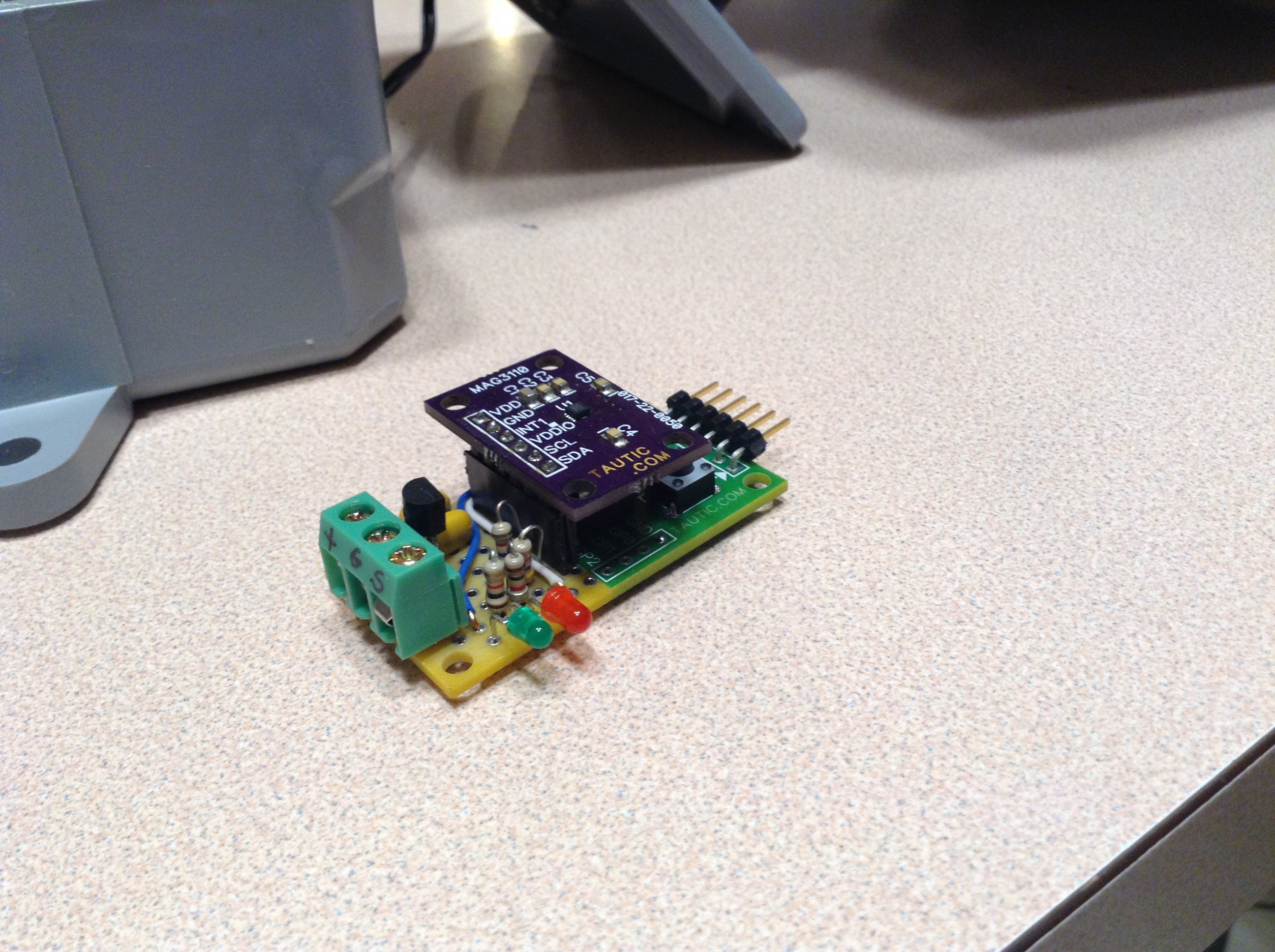
And finally, this is the sensor module. The purple board is a breakout for the MAG3110 magnetometer chip. The actual sensor is the tiny black square in the center of that board. I'm pretty good at soldering, but that tiny chip is a little beyond my ability at the moment. The sensor breakout PCB is mounted as a daughter board to a PIC 8-pin dev board. The pin header at the right end is where the ChipKit 3 programmer is attached to allow reprogramming the PIC microcontroller, which is directly beneath the sensor. To the left of the sensor is the 3V3 voltage regulator which supplies power to the PIC and sensor.
The two LEDs were originally added for debugging the software in the PIC, but I decided that I liked them and left them in. The LEDs can be read as follows:
- When the sensor is first powered up and enters auto-calibration mode, the green LED blinks once for every detected rotation of the magnet in the water meter, for each axis of the sensor. This allows the user to ensure that the sensor is indeed reading a magnetic field.
- Once the sensor has read 5 revolutions and determines which axis it is going to use for the primary measurement, the green LED turns off for a full second, then blinks out a code for which axis it has selected. One blink for X, two for Y, and three for Z.
- The sensor then switches to normal monitoring mode, and the red LED will blink once for every tick (magnet revolution) of the water meter.
Discussions
Become a Hackaday.io Member
Create an account to leave a comment. Already have an account? Log In.