 John Schuch
So, I started working on the code for the sensor/transmitter.
I'd edit code on my bench, flash the chip, haul it all outside to the meter, test it, haul it all back inside, and repeat.
Now, this is Arizona, and it's about 110F out there. I did about 3 cycles of that before I decided something had to change.
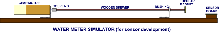
I dug around in my shop and came up with a nice little DC gear motor. I attached a magnet to the shaft and tried it out. I pretty quickly figured out that the windings and magnets in the motor were creating a larger field than the magnet on the shaft. Then I got a piece of dowel and extended the magnet away from the motor. This worked well, I could read the magnet without getting magnetic interference from the motor itself. Then another problem cropped up. I was using a variable bench power supply to run the motor. It worked fine, but when I tried to slow the motor down (water meters can run VERY slowly) by reducing the voltage, the motor would just stall. The slowest I could get the motor to reliably spin was about 20 RPM, not nearly slow enough. It seemed pretty clear to me that what I needed was as actual motor controller, and down another rabbit hole I went.
I decided that I needed a PWM motor controller. Since in a PWM system the motor always sees full voltage (just varying duty cycle) it should run a much lower speeds without stalling. Torque from the motor will also fall dramatically, but in this application there is virtually no load on the motor anyway.
I decided to use a Microchip PIC12F1840 microcontroller for my motor driver. I selected this chip because 1) it has an analog to digital converter built in, 2) It also has a PWM generator on chip, and 3) I had a bunch of them laying around. It only took me a few hours to draw up a schematic, find all the parts in my shop, and put the thing together on a breadboard. You can see the schematic HERE.
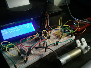
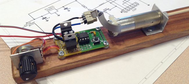
After another few hours, I had basic software running to do the analog conversion of the voltage level from the speed setting pot, and basic functionality of the PWM generator contained in the PIC. In the above picture you'll notice an LCD display. That display is not part of the final circuitry. I have a few LCD displays with serial backpacks installed and find them invaluable for writing code for microcontrollers. They only take up one pin (TX), and you can send all sorts of debug or status messages to them while you're writing/debugging your code. Once the code is done you can pull out the LCD display and delete the display code from your source.
I was going along fine until I hit a roadblock in the code that had me banging my head on my desk for a couple hours. Luckily Jayson Tautic, a friend from IRC, found the bug. Let's just say that MAYBE I should give up doing binary conversions in my head from now on. Changed a "512" to "256", and it ran perfectly. Thanks Jayson!!
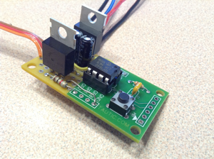
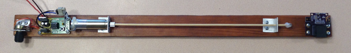
Once I had the code running well, I transferred the circuitry to a little PIC-specific dev board. I tested that construction with the new code and it worked very well. From there, I found an old slat of redwood and mounted the board, motor, pot, magnet, and the sensor. The final result worked perfectly. Using this system I was able to get the motor turning reliably at about 5 RPM. Slower would be better, but that's plenty slow enough to test my sensor, and develop code for the transmitter.
Since this little motor controller project isn't really part of my contest entry, it didn't seem right to fully document it here. I did, however, write up a complete blog post on my website that details the circuitry, and provides all of the source code for the PIC (Public Domain). You can find that page here:
http://hackersbench.com/Projects/PWM/index.html
So that's how I spent Labor Day weekend.
I have two goals for this week:
First, I want to get that solar flood light I bought from Harbor Freight torn apart (the true "hack" part of this project) and start looking into scavenging it's panel, batteries, and charging circuit for this project.
And second, make some serious progress on the sensor/transmitter code for this project. And now, having this simulator, that task will be much easier, and much much more comfortable.
Discussions
Become a Hackaday.io Member
Create an account to leave a comment. Already have an account? Log In.