 U.S. Water Rockets
-
Replacing the wimpy Belt Tensioners to improve positioning accuracy
09/16/2016 at 17:46 • 0 comments![]()
The very first improvement we could make to the MPSM which was fairly obvious right off the bat was that the stock bent tensioning system used spring clips, which have a relatively low spring force, and could easily flex during fast translations, leading to overshooting or undershooting artifacts in the print.
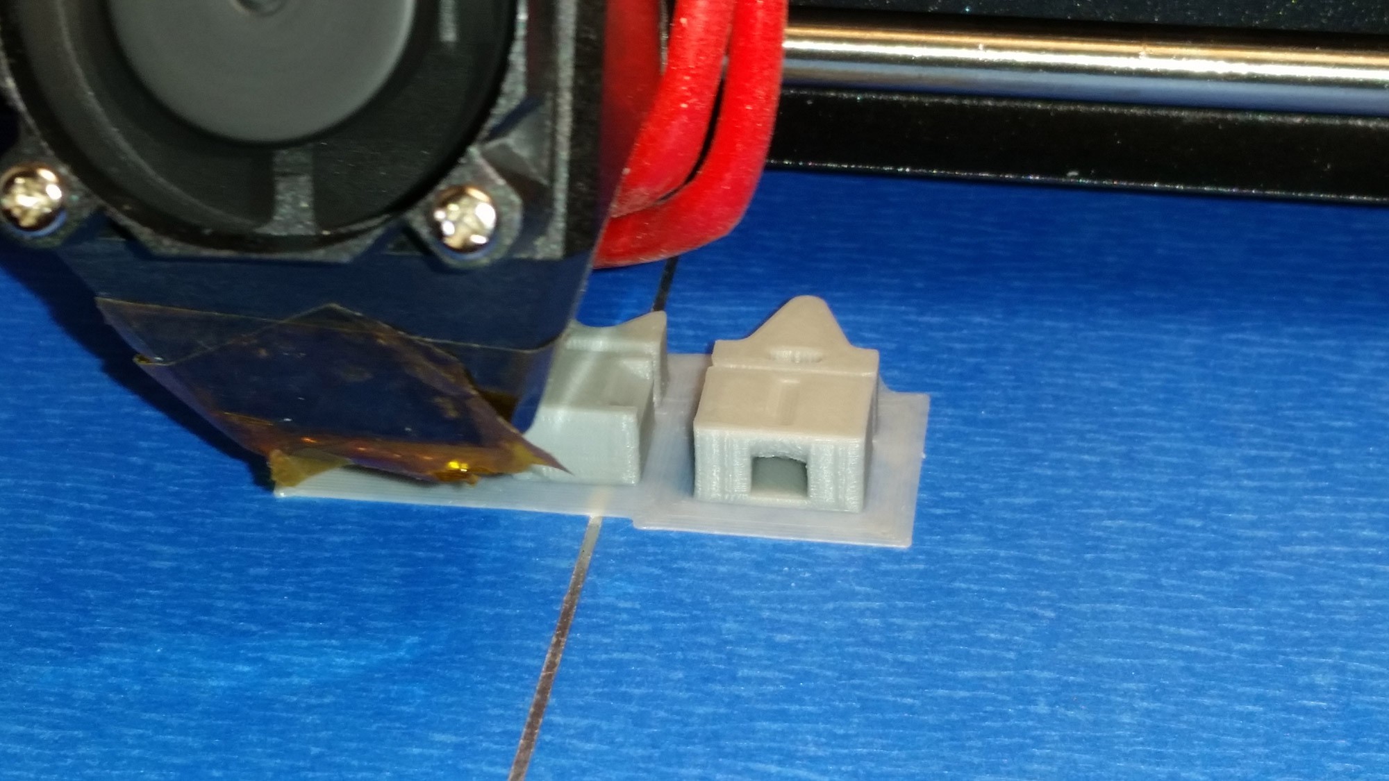
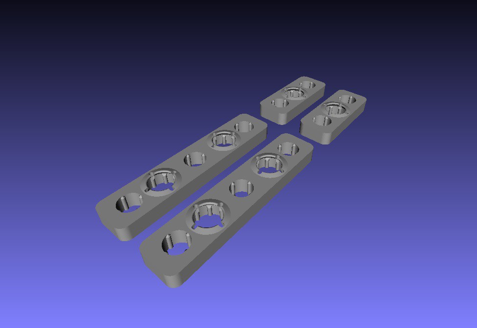
Our solution to this issue was to create and print some new rigid Belt Tensioning Clips for the X and Y axis belts. We whipped up a prototype and printed it on the MPSM itself.
You can find the belt tensioner files on our thingiverse page at: http://www.thingiverse.com/USWaterRockets
![]()
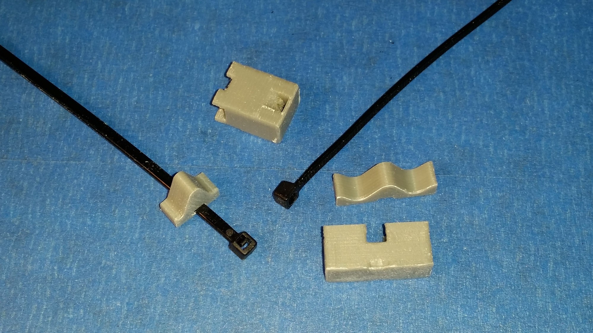
After printing the new tensioners, the old ones were removed and the new ones were installed in their place. The new tensioners use a cable tie to compress two halves together to deflect the belt and provide tension. Tension is adjusted by tightening the cable tie. Note that the tensioners differ for the two belts. This is because the space available to place the tensioners in each axis was not the same, so we had to get creative with the shape of the tensioners.
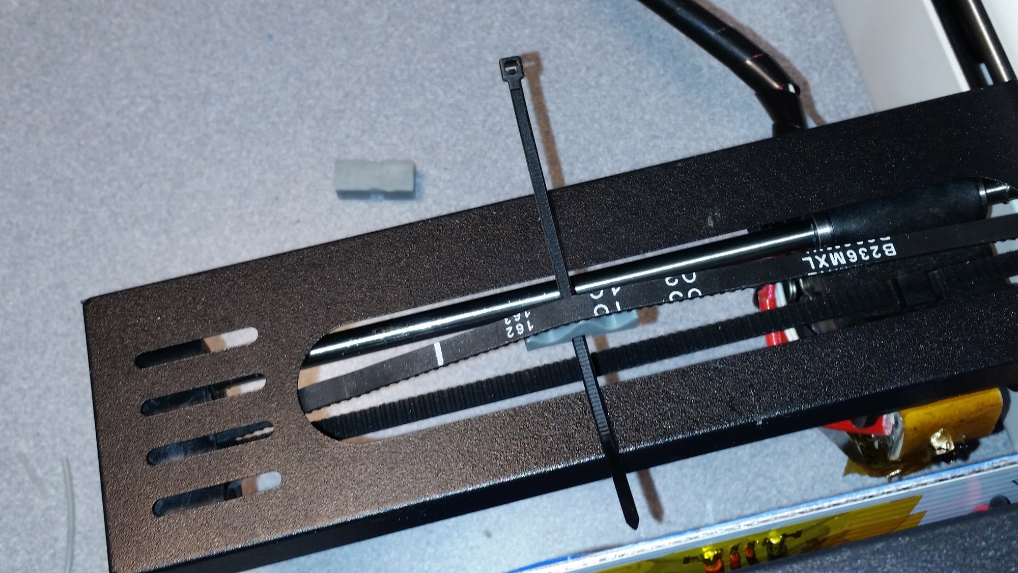
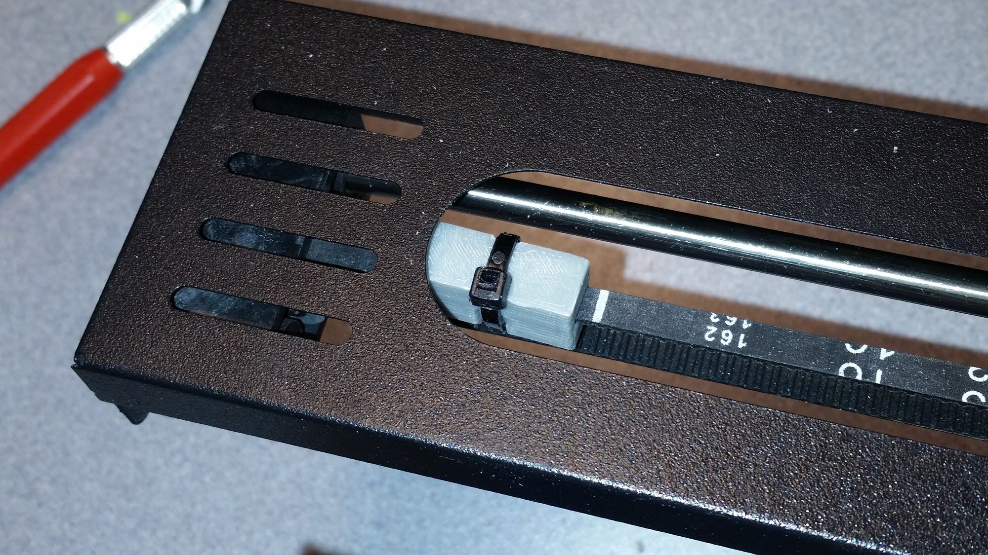
![]() The X-Axis belt runs behind the extruder carriage and is the more difficult to install. The tensioner and clip must be installed on the belt so that it does not hit the pulleys when the extruder is fully travelled to either end. You can find a suitable spot to place the clip by moving the extruder head to the minimum and maximum position and finding a spot along the belt in the middle of those extents.
The X-Axis belt runs behind the extruder carriage and is the more difficult to install. The tensioner and clip must be installed on the belt so that it does not hit the pulleys when the extruder is fully travelled to either end. You can find a suitable spot to place the clip by moving the extruder head to the minimum and maximum position and finding a spot along the belt in the middle of those extents.Also be careful to place the tensioner on the belt with the larger side facing the rear of the printer, or the clip could rub on the carriage as it passes by.
![]()
Position the tensioner as shown and support it with the cable tie.
![]()
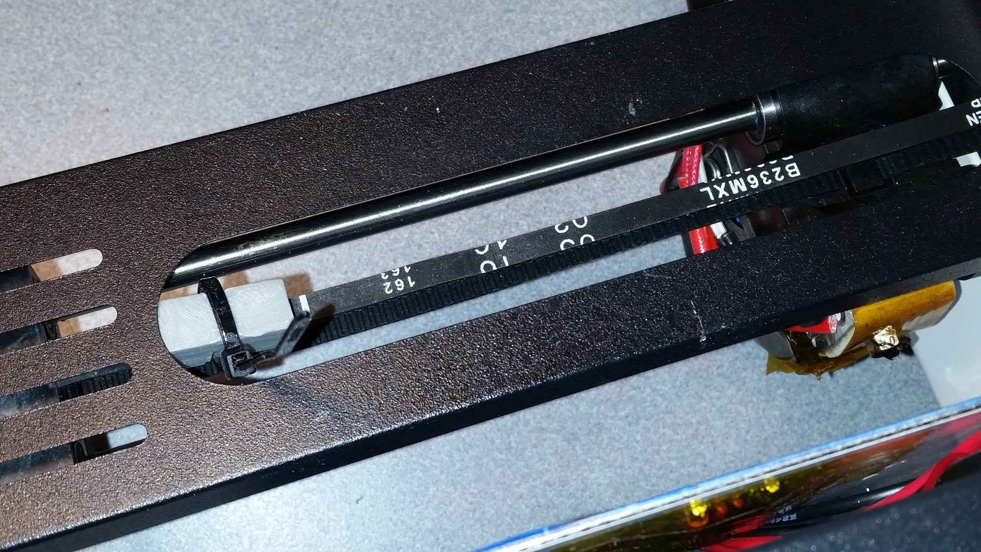
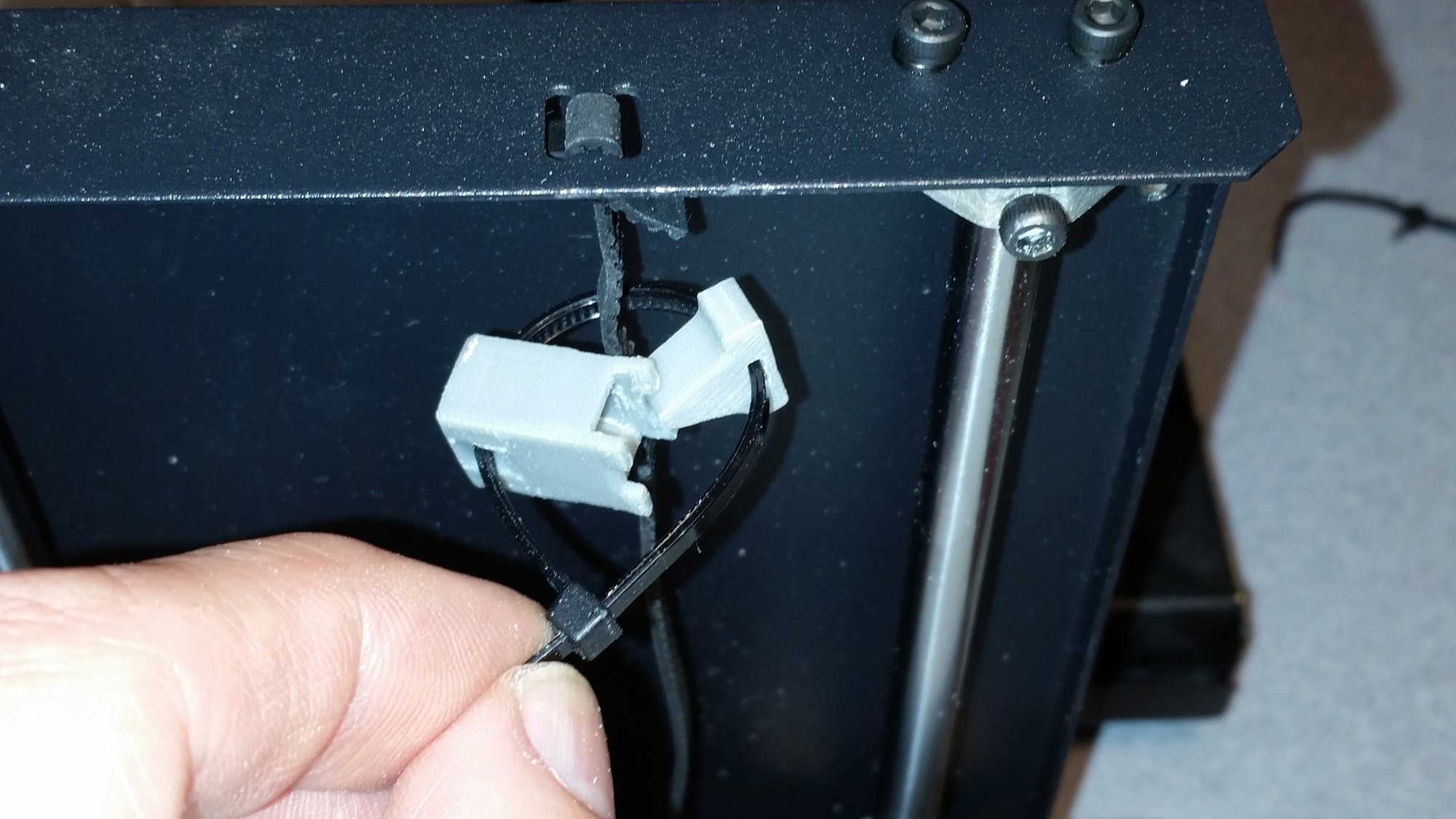
Loosely close the tensioner with the cable tie and test that it is in the location you prefer.
![]()
Then you can tension the cable tie to tighten the belt and trim off the excess cable tie.
![]()
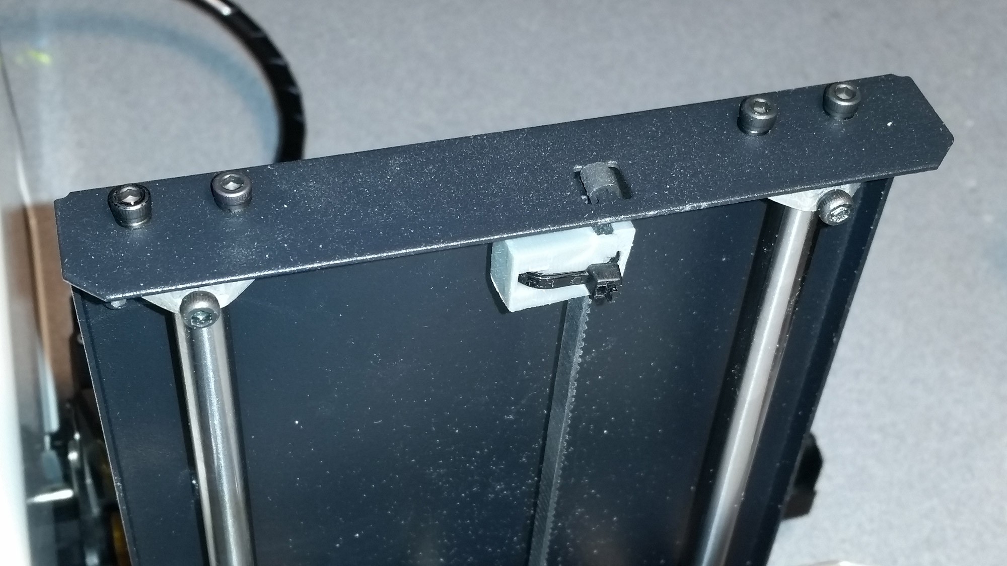
The second clip for the Y belt is located under the metal tray that supports the build plate near the front of the printer. This one is easy to install with no real issues.
![]()
Place the Y Axis tensioner as far forward to the front of the printer as possible. that will insure it will not interfere with the pulleys under the tray or the limit switch.
Adding the clip to the Y belt put increased tension on the Y axis bearings, and eliminated some noticeable slop in the bearings on the stock printer. The total cost of this upgrade was a few cents in filament and cable ties? Maybe $0.25 if you really rounded up?
This upgrade was well worth the effort.
-
Adding 3D Printed Z-Axis Rod Stabilizers
09/16/2016 at 19:04 • 6 comments![]()
Get the latest version of this part on our Thingiverse Page right here: http://www.thingiverse.com/thing:1775502
While disassembling the printer to add some accessory wiring (to be explained in a future project log) we observed that the Z-Axis linear rods were somewhat loose. After inspecting the assembly, it was apparent that the 4 brackets which hold the rods in place at the top and bottom of the printer have a hole which each rod seats in which is slightly oversize. This is likely to insure that variations in part tolerances will not prevent the parts from fitting together.
The downside to the oversize bracket holes is that it allows for some play in the rods, which is magnified the farther along the X axis the hot end moves out. The gantry acting as a lever multiples any play in the rods. This issue can lead to defects in prints. Further compromising the design is the discovery that the rails are cut slightly shorter than the distance between the brackets, This is also obviously done so that the rails could be cut with loose tolerances and would always fit in the printer, but the downside of this approach is the rails can also move up and down in their brackets, as they float freely in the brackets with a small gap on the top and bottom. The combination of loose tolerances in the brackets and rods also contributes to making the printer noisy, as these loose rails tend to rattle under certain conditions.
![]()
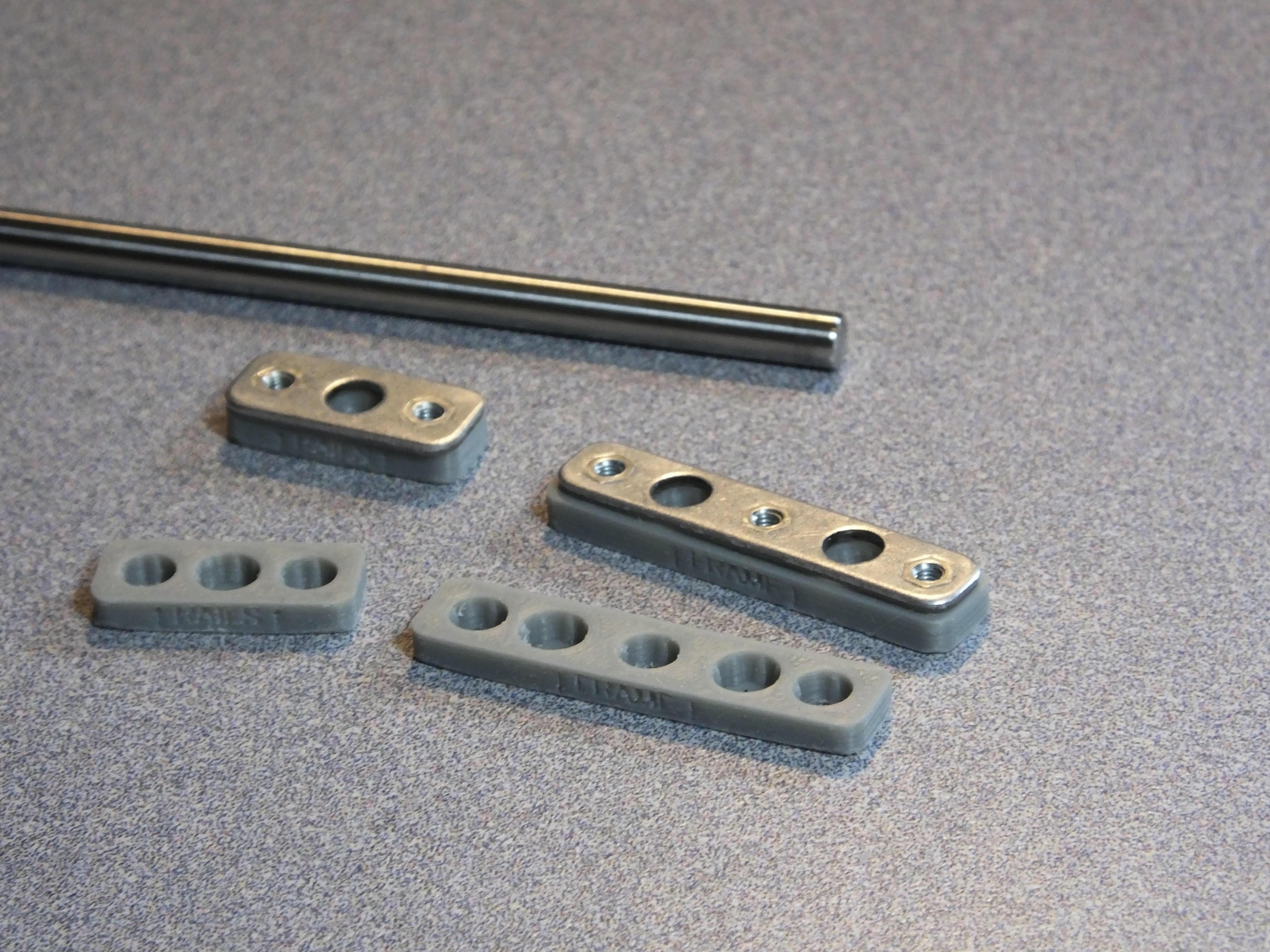
Our solution was to print some stabilizers which would fit under the existing brackets and through the inclusion of a tapered hole for the rods, the rods would be centered in the stabilizers and held firmly in place. These stabilizers were designed and printed but upon testing we discovered that variations in the lengths of the rods and possibly in the bends of the sheet metal enclosure would lead to different length of rod protruding into the tapered seat, so longer rods would push farther in than shorter rods. This causes the shorter rods to be held less firmly than the longer rods, so the stabilizing was not uniform depending on rod length.
Our second design solved the issues we discovered. The improved stabilizers eliminate the tapered seat for the rods and have a feature on the outboard side of the stabilizer which is designed to flex outward when the rod is inserted. This feature is tapered in a way that causes it to compress very tightly around the rod when the clamp is installed.
![]()
To install the rod stabilizers, we had to remove the covers from the bottom of the printer and rear of the tower. Then we removed the M3 Cap screws which hold the rail brackets to the top and bottom of the tower. There are two brackets with 3 screws and two brackets with 2 screws.
We also removed the Z-Axis stepper motor by loosening the grub screws holding it to the threaded rod for the Z-Axis, and the two screws holding the stepper motor in place. This let us slide the gantry assembly out of the rear of the printer and slide the rails off the brackets.
![]()
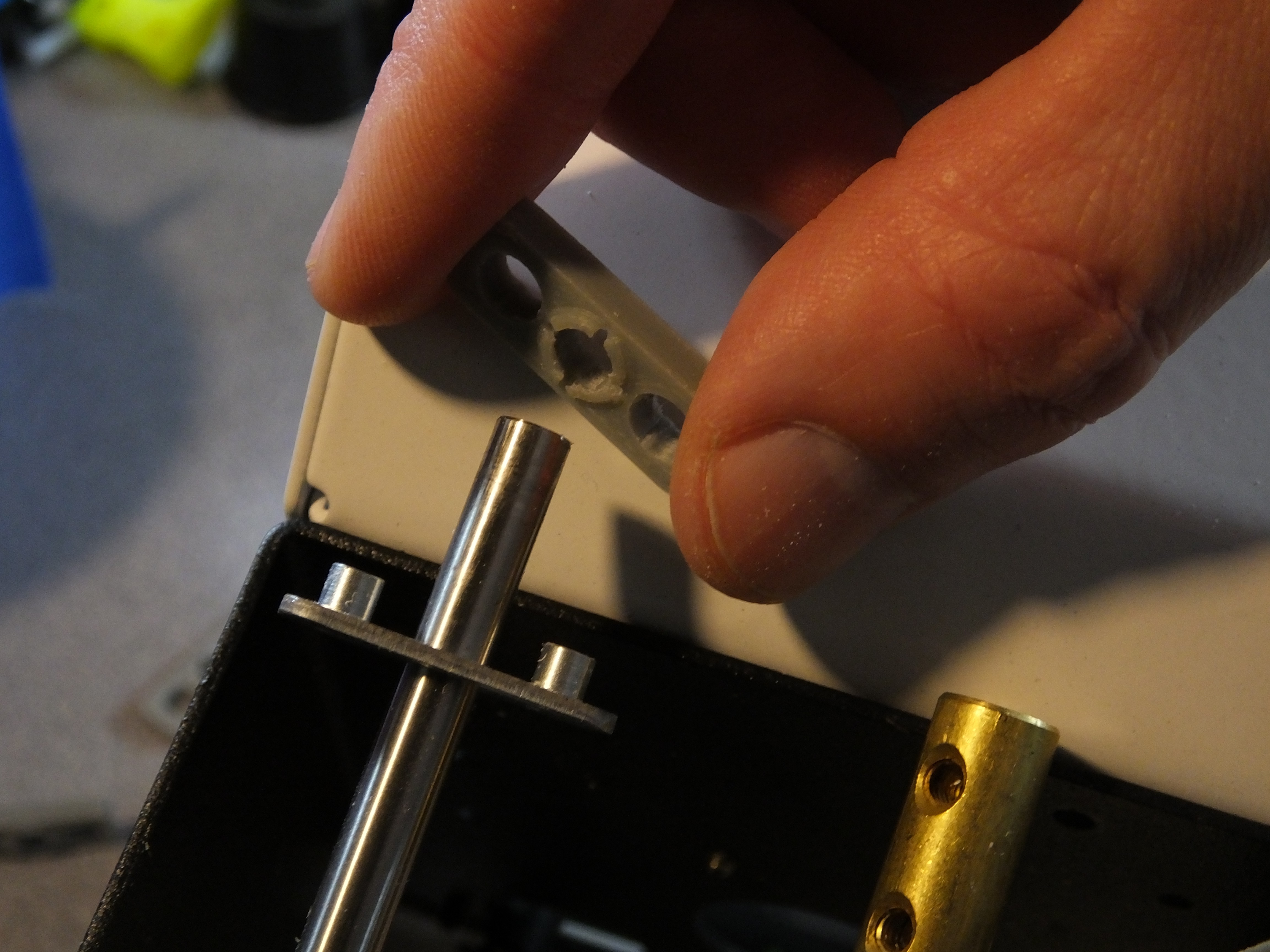
Installing the printed stabilizers was very straightforward. The first step is to slide one of the brackets over the rod. The next step is to push the rod into the stabilizer through one of the rod openings. The rod should be hard to press into the hole, as it has to spread the opening to pass through. This is normal. The stabilizers only go on one way, so make sure you are pushing them on with the clamping feature facing the bracket. The third step is to realize you forgot to put the bracket on and so you have to remove the stabilizer and then start over with the bracket.
![]()
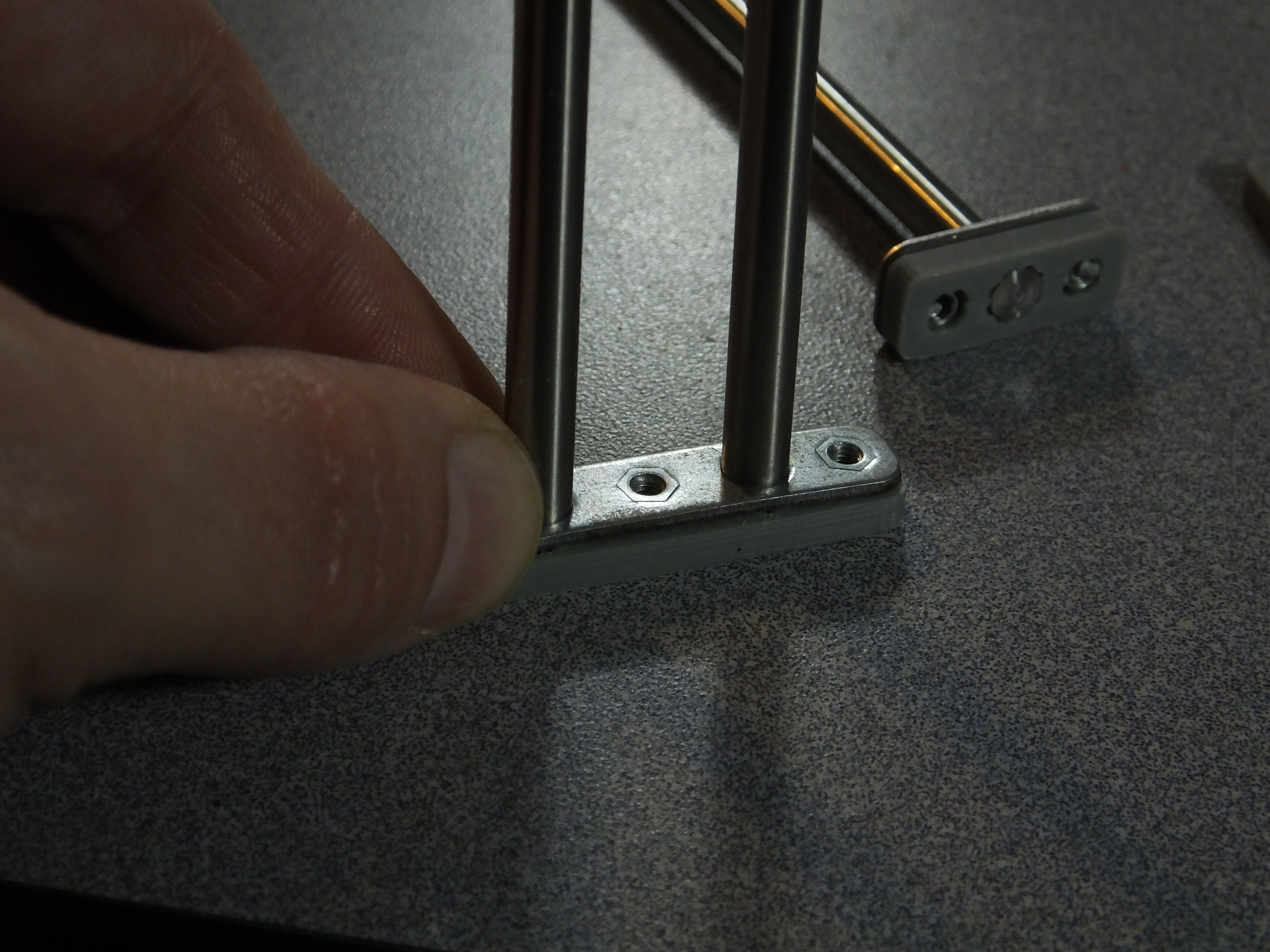
With the stabilizers in place, you can slide the brackets down and in place over them. The brackets have tight tolerances with the holes in the stabilizers, so make sure toy press them straight on. They should snap in place against the brackets with a little effort.
Now, you can reinstall the assembly in the printer tower. When you tighten the cap screws on the brackets, the clamp features on the stabilizers under the brackets will constrict tightly around the rods and secure them from moving.
![]()
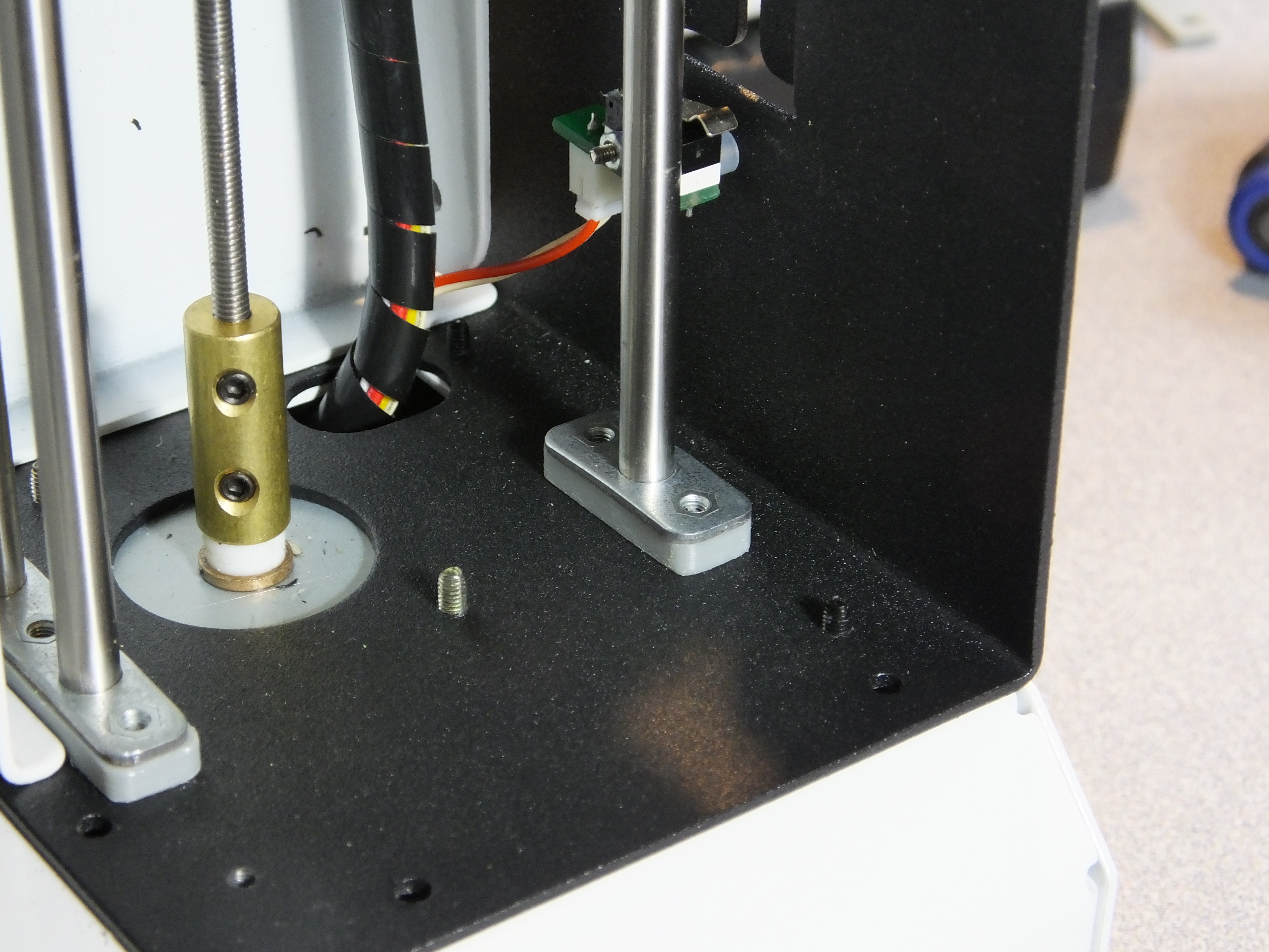
You can now reassemble the rest of the printer and you should see less play in the tower!
Congratulations! You've just made a huge improvement to the Z-Axis stability for a few pennies of filament and a little of your time!
-
Zero Offset E3Dv6 Clone Hot End Mount
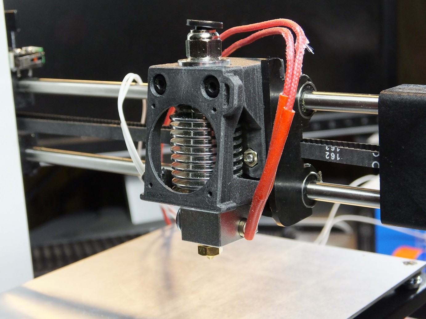
09/23/2016 at 17:15 • 8 commentsWhen the Monoprice Select Mini was first featured on HaD, the recommended first modification to perform was to swap out the hot end for an E3Dv6, using a 3D Printed mount. Before I even had the printer, I had ordered a $6.00 clone from Amazon, with a 0.25mm nozzle, anticipating that I would need the new hot end to be able to use commonly available nozzles in various sizes and materials. At the time, I was not aware that the stock hot end could work with common nozzles. I could easily swap out the stock nozzle and save some money, but after thinking about it a bit more I decided that I really wanted to have a separate hot end cooling fan and hot end layer fan, for better control over bridging and overhangs.
I looked at the available fan mounts that had been published when I received my MPSM, and I was not excited because they offset the nozzle quite a bit from stock, they pushed the nozzle down in the Z axis, and forward in the Y axis. This causes the nozzle tip to move almost all the way off the font of the build platform, and requires that the leveling screws get cranked way down to clear the nozzle.
![]()
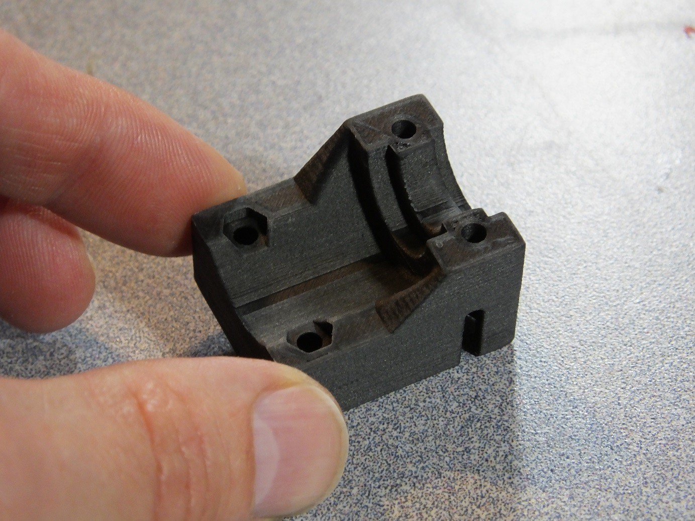
I didn't like losing build volume, due to the offset, so I started work on my own adapter design that retained the position of the nozzle as much as possible. Once I found the correct position for the nozzle, it was apparent that the strength of the screw mounting would be compromised because the space available was very thin. But I realized that I could extend the bracket inside the hollow cavity in the carriage, and use the walls and bosses in the cavity for strength. The screws would merely hold the bracket without experiencing much force.
![]()
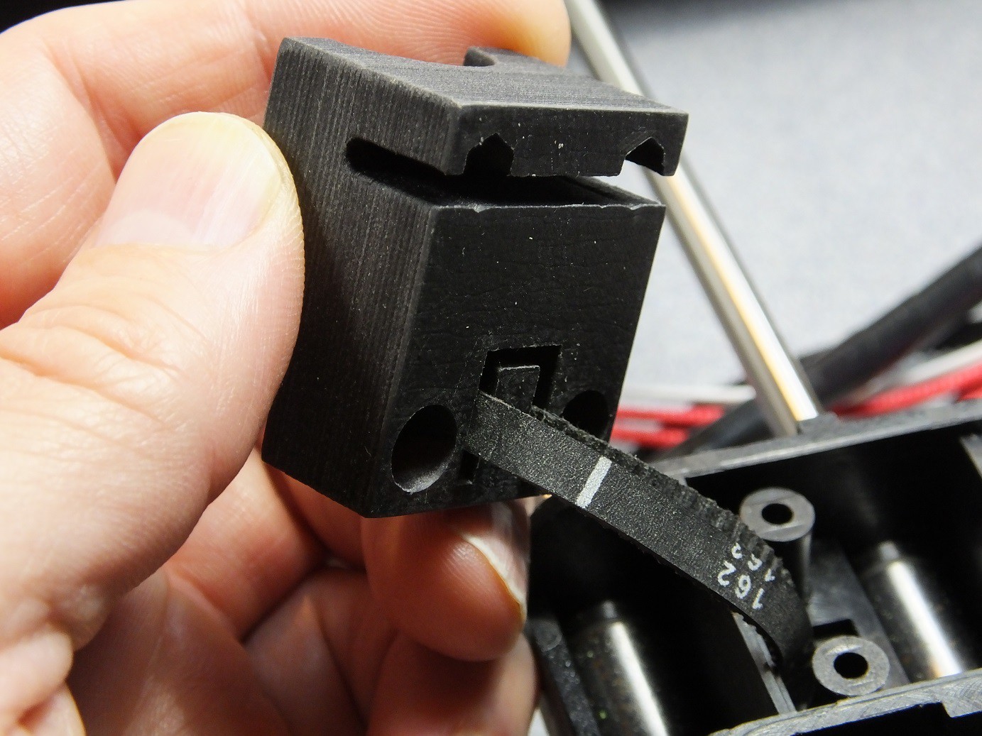
With the printer torn down to this level, I noticed the way the X-Axis belt was fastened, and it gave me an idea. I made a similar tab on the rear of my hot end adapter, so that the belt tension would hold it in place instead of the screws, which I would eliminate.
Ultimately, when I tested this design, the flexibility of the belt did not hold the bracket as firmly as I wanted, so I put the screw mounts back into the design. However, I noticed that the belt grip on the back actually acted like a belt tensioner, by removing slack from the belt.
![]()
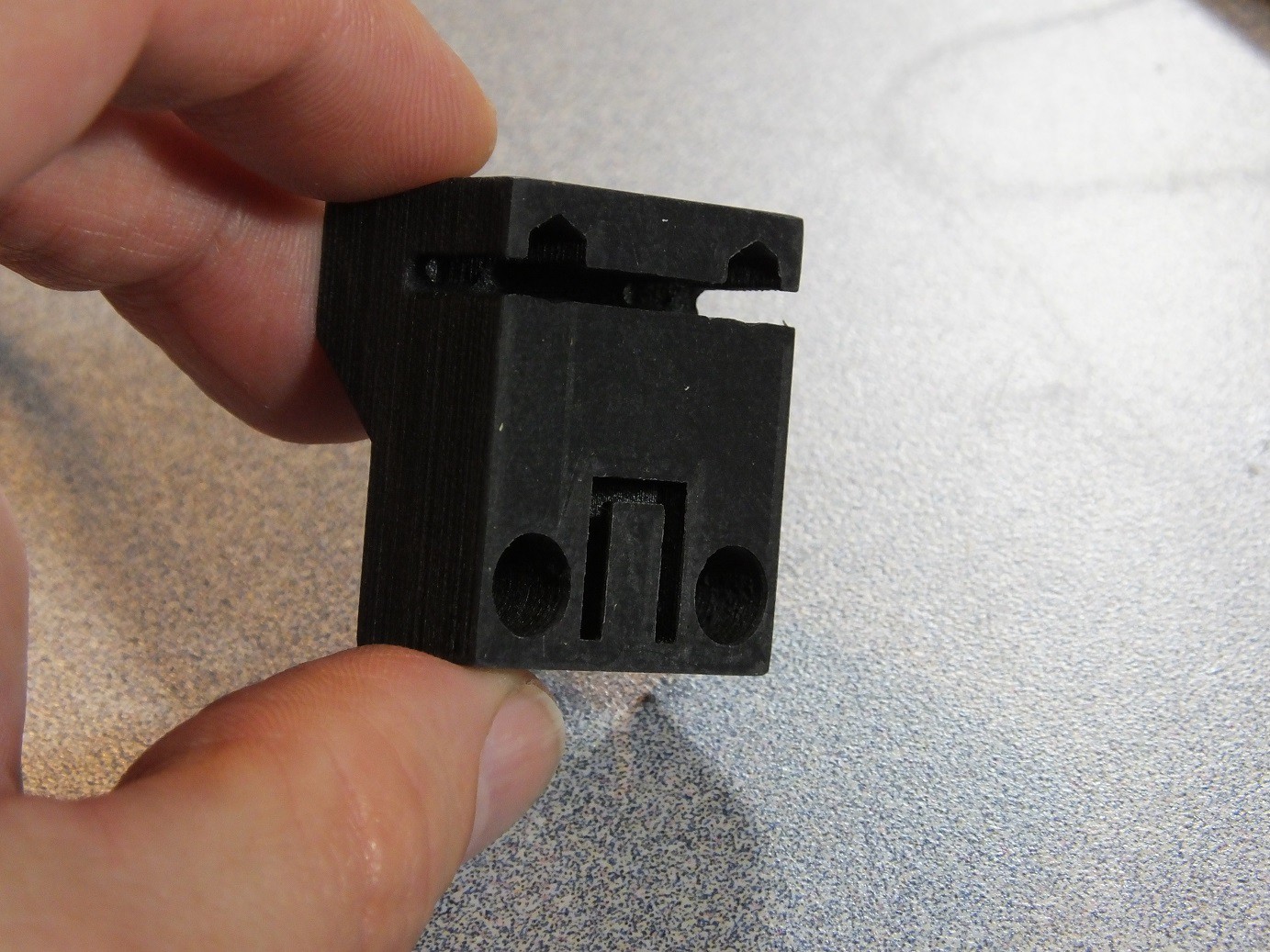
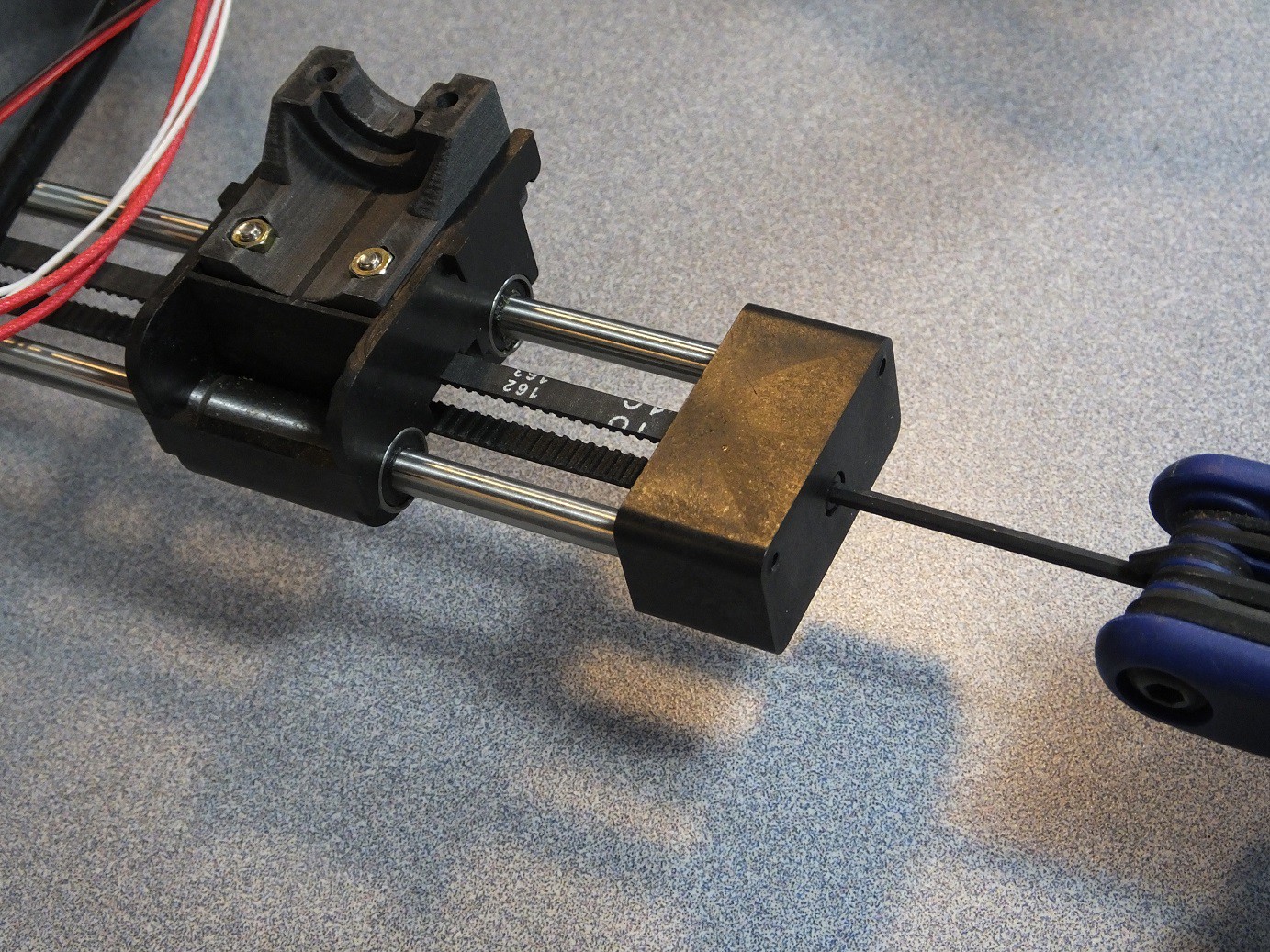
The final design includes both the belt tensioning feature and the screw bosses, and holds the mount very securely.
![]()
![]()
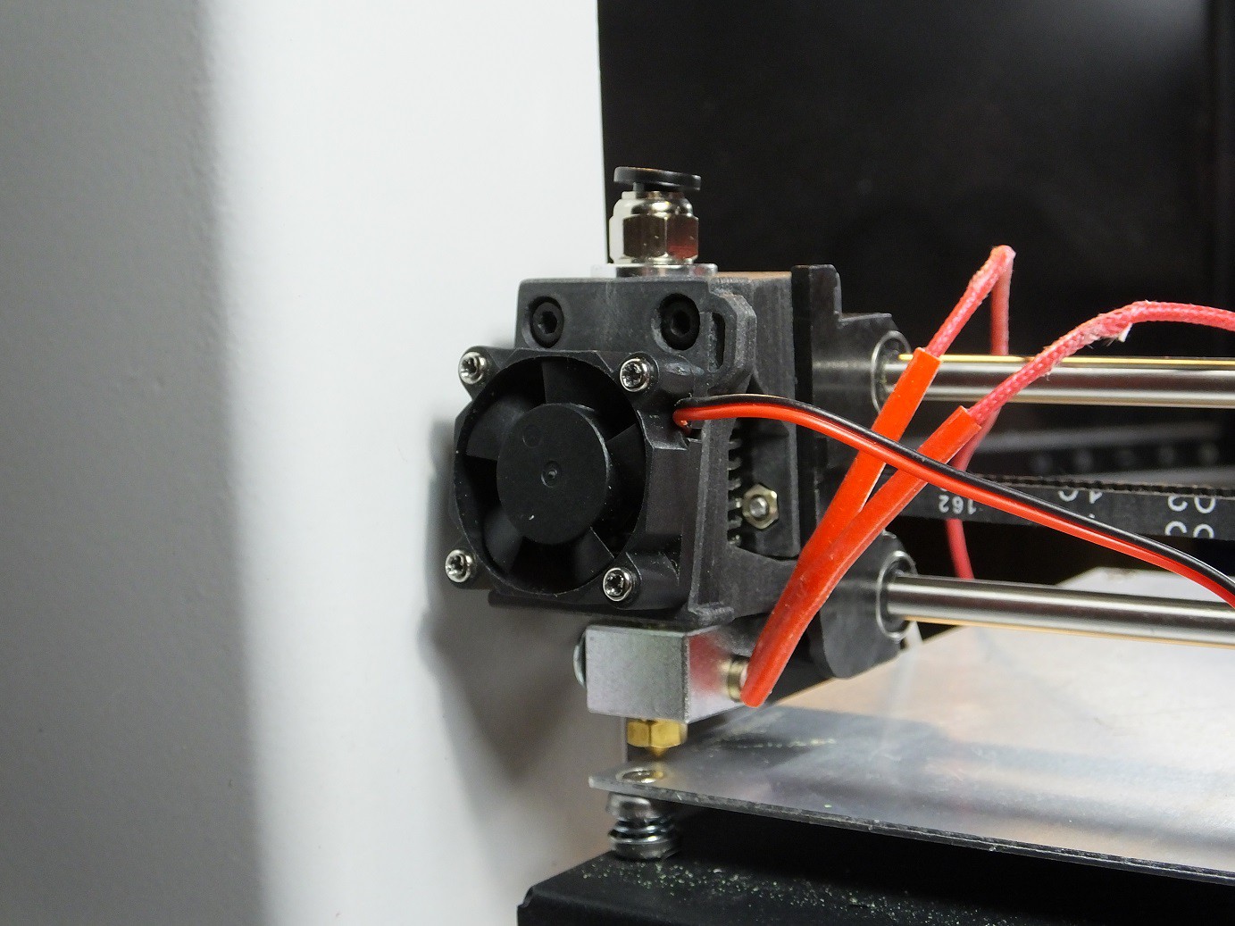
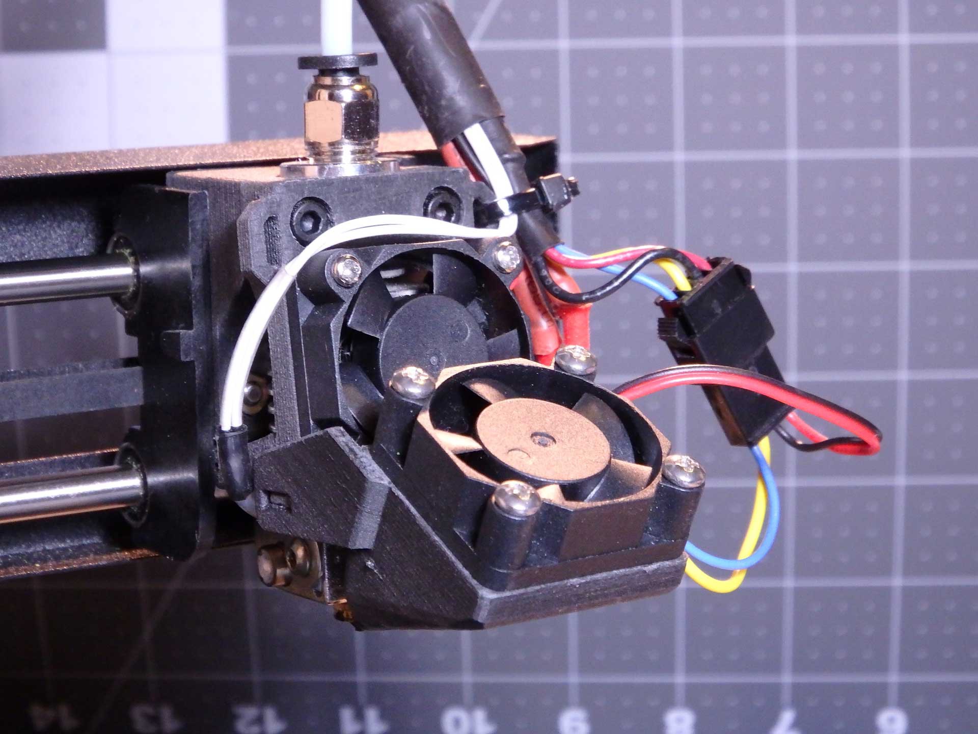
With the mount installed, I then created a fan shroud which would direct cooling air through the heat sink on the E3Dv6 Clone. This shroud design would double as the mounting clamp for the hot end, would have to be designed to maximize the cooling, and direct the exhaust air away from the print, to help prevent ABS warping. A layer fan accessory would attach to this shroud to provide controlled cooling for bridges and where needed.
![]()
The new mount shown here takes a 30mm fan, from the E3Dv6 clone. The stock heat sink and fan had no problems with filament temperatures up to 270C, so the E3Dv6 clone with the superior heat sink and larger air evacuation ports in the shroud should work just as well. Using a larger fan seems like an unnecessary change at this time.
![]()
The hot end fan was installed on the shroud, and looks like it will work great. There is still quite a bit of wiring to be done to make this all work, so I have not been able to test it yet. The internals of the printer are still spread out over the table beside the printer.
![]()
This is the new "Home" position of the new hot end nozzle tip, using this bracket. I estimated the position based on where the limit switches engaged. The bed didn't require any adjustments, and the Y-Axis seems very close to where I recall it was before I began. I should have taken some photos for reference, but I forgot.
Next up is some wiring and electrical modifications!
-
A Really Cool Part Fan
10/26/2016 at 01:51 • 2 commentsThe next improvement we are making to our Monoprice Select Mini is the addition of a Part Cooling Fan, which is a separate fan with directed air flow that is controlled by the Fan Output of the control board.
This means we had to rewire the fan attached to the E3Dv6 Fan, so that it will run when the printer is switched on, and take the existing fan wires, and connect them to the Part Cooling Fan. This way, fan control options in the slicer will be able to change the fan speed of the part cooling fan and turn it off for better bed adhesion without causing heat creep leading to jams in or above the heat break.
To make the fan attachment even cooler, a pair of 3mm White LEDs were built into the air duct to illuminate the print area under the nozzle.
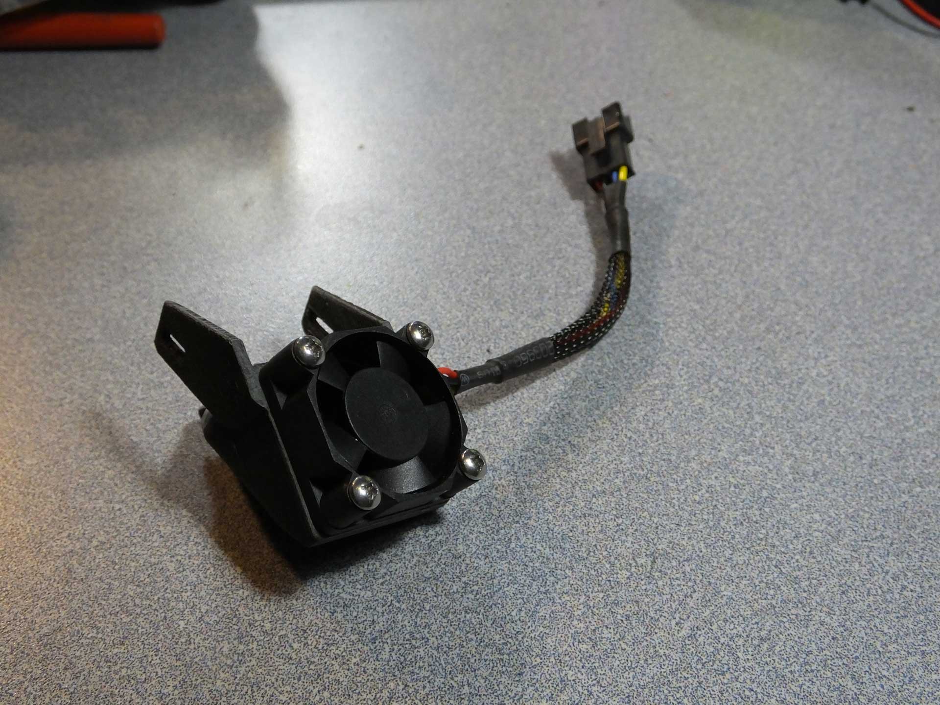
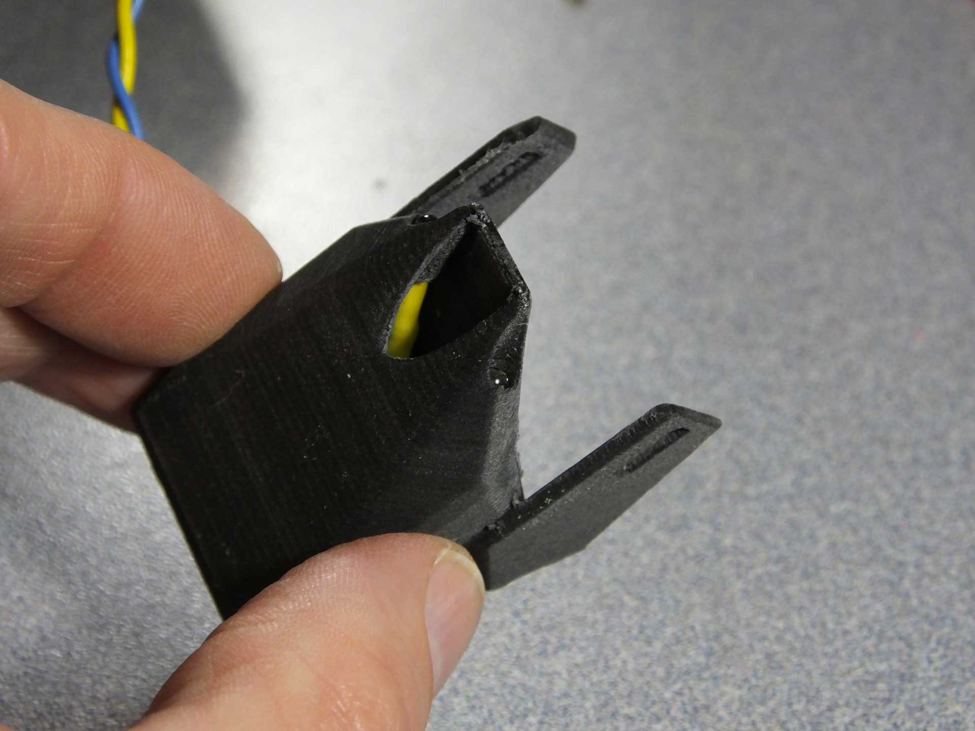
![]() This is that the Part Cooling Fan looks like when it is removed from the E3DV6 Mount. Notice that it has a JST style connector so that I can swap in different fans and LED lights in the future as I design new styles.
This is that the Part Cooling Fan looks like when it is removed from the E3DV6 Mount. Notice that it has a JST style connector so that I can swap in different fans and LED lights in the future as I design new styles.
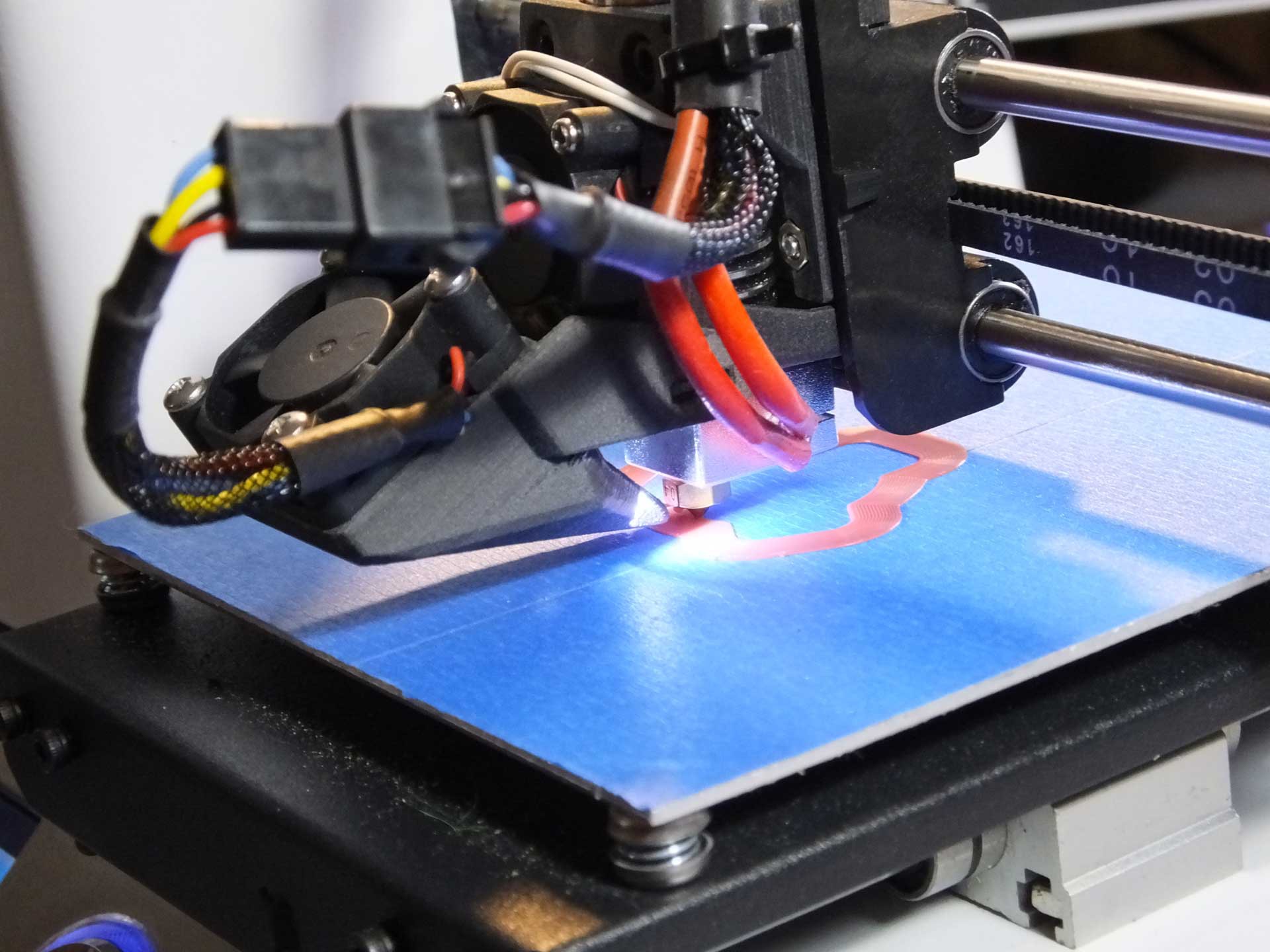
![]() The outlet of this nozzle directs all of the air flow directly on the extruded plastic that has just exited the nozzle. This is intended for improving overhangs and bridges. You can also see the LEDs that illuminate the print beside the outlet.
The outlet of this nozzle directs all of the air flow directly on the extruded plastic that has just exited the nozzle. This is intended for improving overhangs and bridges. You can also see the LEDs that illuminate the print beside the outlet.
![]()
Here is a very short video clip of the Zero Offset E3Dv6 Mount and LED Part Cooling Fan in action.
This modification was hard to put a price on because we had most of the parts laying around. The fan came from the E3Dv6 and the JST connectors were in an assortment we had, and the wire was salvaged from an old PC. Even if these parts were sourced new, the total would still likely be under $5.00US.
-
Zero Offset E3Dv6 Hot End and Part Cooling Fan Files are Now Available
10/26/2016 at 02:06 • 2 comments![]() The files and installation instructions for this setup are now available on our Thingiverse Page. To download these files, please go to:
The files and installation instructions for this setup are now available on our Thingiverse Page. To download these files, please go to:http://www.thingiverse.com/thing:1848402
Thanks for your feedback and comments! We appreciate the encouraging words!
-
Fixing Heated Bed Heater Failure, Sensor Failure, and Y-Axis Wobble/Errors
10/29/2016 at 20:07 • 3 commentsWhile fixing issues with some wobble in my Y axis, I noticed an issue with the wiring that will cause many problems with the heated bed. I has seen on my prints that there always was a bit of slop in the layer alignment, especially in the Y axis (front to back). Nothing really that serious, but enough to be annoying. I thought it was probably due to the way the belt is attached to the bed, or something in the drive pulleys under the bed. I was going to look at it eventually, but I believe I discovered the cause of the error while I was working on a different modification I was doing.
![]() Check out the video below and see if you can spot the issue before I explain it and discuss my solution.
Check out the video below and see if you can spot the issue before I explain it and discuss my solution.
As you can see in the clip above, the way the wiring for the heated bed is placed under the bed, as the bed moves back and forth, the wiring rubs on the belt and actually deflects the belt a couple of millimeters as it makes contact. The belt deflection in this way, is certainly causing the bed to shift slightly font to back as the belt tension changes. Fixing this issue can only make things better. This is certainly going to damage the headed bed sensor or heater wires, as them move back and forth.
I was able to shift the position of the wires under the bed a little and get them to stop wobbling the bed, but after many prints the heater began to heat only intermittently, and it would stop heating if I pushed it all the way to the rear. Eventually it stopped heating, and I thought perhaps the wiring was coming loose from the movement under the bed. I used the printer without the heated bed for some time but then the bed temperature sensor started to report crazy values while printing.
![]()
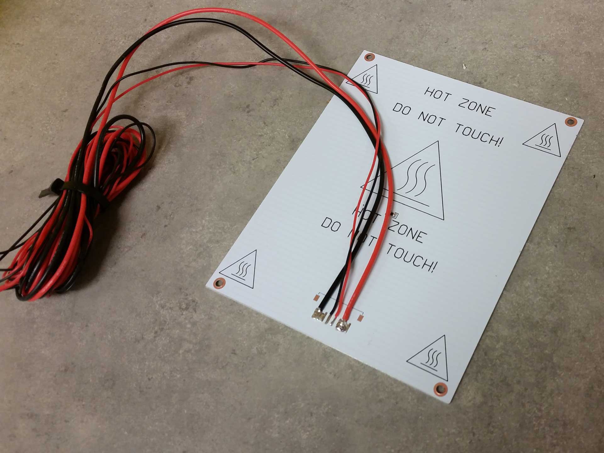
I was pretty sure it was the wires under the bed getting damaged from the motion. When I investigated the problem, I ran into an obvious broken wire under the bed. The thinner wires going to the thermistor were not visibly broken, but under the insulation the wires were failing and I could make the temperature on the screen change to crazy numbers by shifting the thin wires around. It looks like I would have to replace the wiring on the heated bed. But how would I correct the issue?
![]() My solution was to replace the heated bed wiring with better quality wiring and route it so that there would be no stress on the wires and no interference with any of the moving parts. For the wiring, I chose to use silicone jacketed wire which I had on hand for my rocket and quadrotor experiments, which I purchased in bulk from Hobbyking. I probably only used a dollar or so of the wire if I were to buy it separately.
My solution was to replace the heated bed wiring with better quality wiring and route it so that there would be no stress on the wires and no interference with any of the moving parts. For the wiring, I chose to use silicone jacketed wire which I had on hand for my rocket and quadrotor experiments, which I purchased in bulk from Hobbyking. I probably only used a dollar or so of the wire if I were to buy it separately. Soldering the wires to the heated bed proved to be a challenge as the aluminum would keep the iron from heating the solder. I ended up warming the whole bed up with a heat gun and then soldering the wires. Pre-heating the aluminum was enough to let the soldering iron work on the joints.
While I was in there, I also reflowed the thermistor with some lead solder I had on hand. No-lead solder is notorious for being brittle, and other people have reported that their thermistors fail from heat expansion/contraction cycles of the board, or from flexing the board during print removal. By flowing the joints with more flexible lead solder, I hope to prevent any of these issues on my heated bed.
![]()
I applied liberal amounts of Kapton Tape to make sure nothing would ever short out, or pull loose. I also dressed up the wires with more of the cable sleeve I salvaged from a discarded PC a while back. It dresses up the wiring, and probably helps with strain relief of the moving wires.
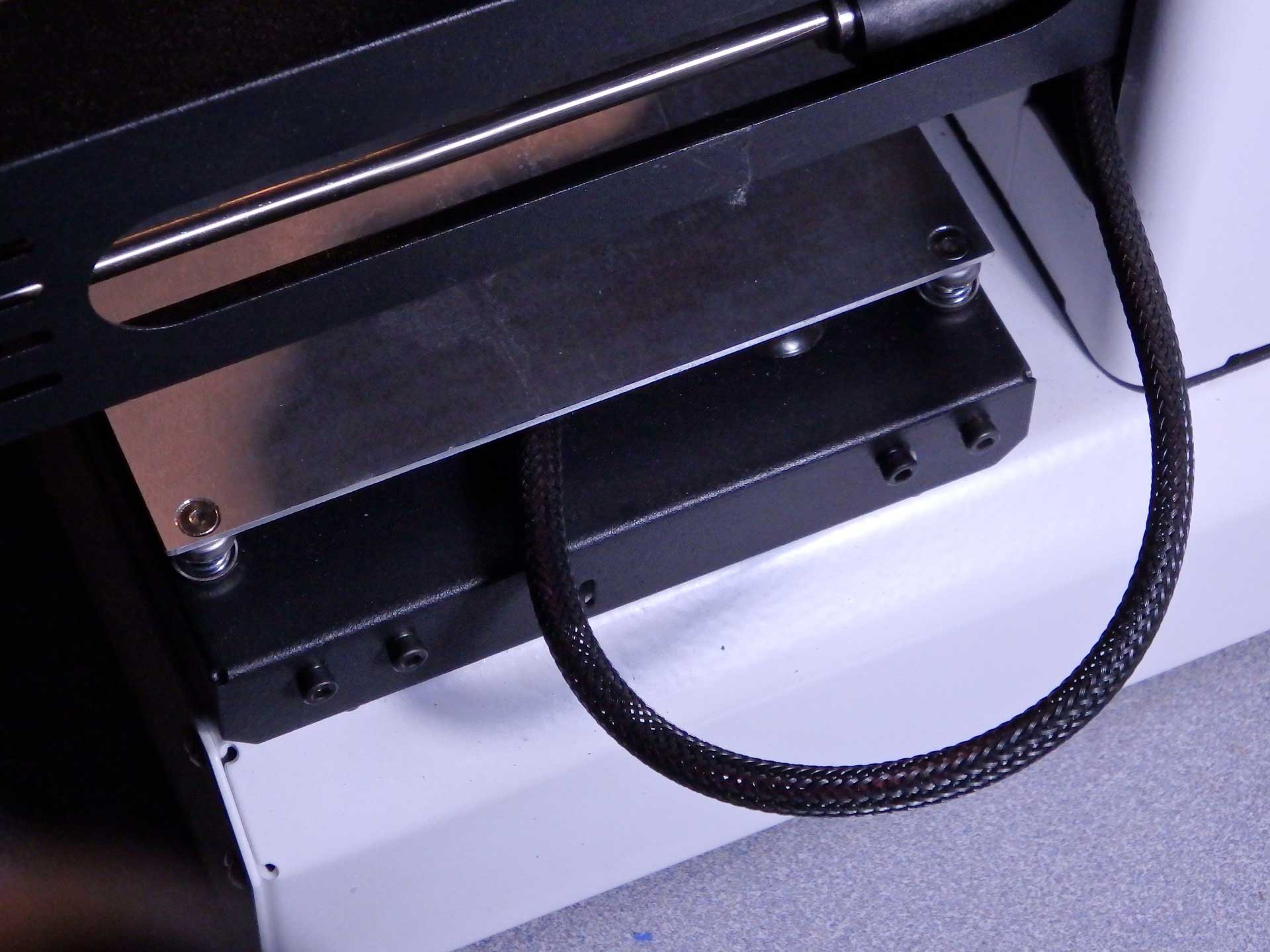
![]() To solve the original Y-axis belt rubbing problem, I re-routed the heated bed wiring through the slot in the Z-axis tower. The gantry never lowered enough to interfere with the wiring, and the new cable routing solved all the issues with the belt. The wire actually moves very little ones it is not confined under the bed. This wire configuration should be standard on the Mini.
To solve the original Y-axis belt rubbing problem, I re-routed the heated bed wiring through the slot in the Z-axis tower. The gantry never lowered enough to interfere with the wiring, and the new cable routing solved all the issues with the belt. The wire actually moves very little ones it is not confined under the bed. This wire configuration should be standard on the Mini.![]() Ultimately, I decided I didn't like the length of the heated bed wires, so I decided to make a hole in the back of the printer and transplant the rubber grommet from the bed to the rear of the printed, and feed the wires directly out the back of the printer below the bed. I like this approach because I was able to make the wiring a lot shorter. This is even better and should really be the way the printers are built from the factory (even better than my last suggestion).
Ultimately, I decided I didn't like the length of the heated bed wires, so I decided to make a hole in the back of the printer and transplant the rubber grommet from the bed to the rear of the printed, and feed the wires directly out the back of the printer below the bed. I like this approach because I was able to make the wiring a lot shorter. This is even better and should really be the way the printers are built from the factory (even better than my last suggestion).I think I would like to design a printed cable attachment point to one of the screws that attaches the rod ends to the bed tray. Right now the kapton taps is really the only thing that secures the wiring to the bottom of the bed.
Watch this space for an update when I have the printed part designed and test fit.
-
What to do if you're not a fan of constantly running fans?
11/02/2016 at 18:50 • 3 commentsI'm not a big fan of having the cooling fan for my hot end running all the time, or having the LEDs on my hot end running all the time, I also wanted to add a cooling fan to my control board inside the printer, but I did not want to have that fan running all the time either. Other printers solve these issues by using software controlled outputs to turn these various peripheral devices on and off only when the printer is printing. I wanted to do something similar, but because the firmware of the printer is closed source and there are no extra outputs on the board to use for this purpose, I had to add this function the old fashioned way: with a circuit hack.
![]()
The general principle for this hack is to tap into the heater power and use the operation of the heater in the hot end to turn on and off the fans and LEDs. This is not nearly as simple as tapping into the heater power and using it to operate everything, since the heater is controlled by the software and it is pulsed on and off for various time periods to simulate an analog signal. By varying the amount of time the heater is on over a specific time period, a more precisely controlled temperature is achieved. For example, if you turn the heater on for 1 second out of every 10 seconds of elapsed time, the heater would be getting 10% of the energy it would get if it was on constantly. Therefore, the heater would be about 10% as hot. This pulsing of a digital value to simulate an analog value is called "Pulse Width Modulation" or PWM for short. This prevents us from using the heater control directly to control our fans and LEDs because they would be pulsing on and off as the controller tries to regulate the temperature of the hot end.
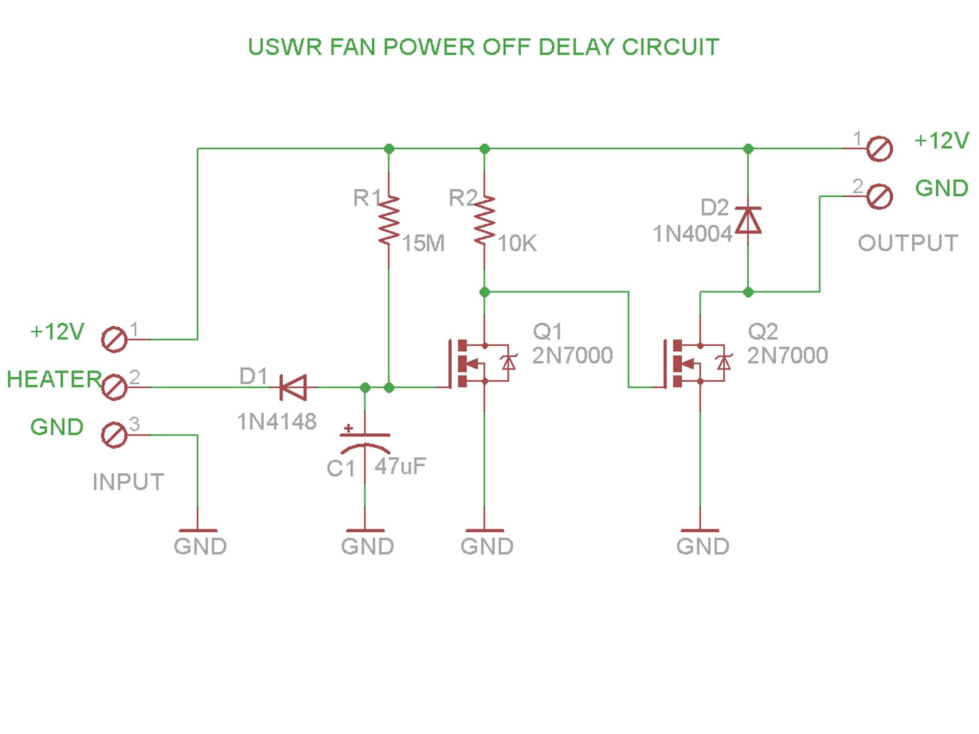
The solution to this issue is to create a circuit that is essentially a delay timer that will start counting when the heater is pulsed, and stops counting when some time has elapsed without activity on the heater. This is certainly a trivial thing to do with an Arduino, but we're going to do this the old fashioned way, with whatever scrap parts we have in the lab. Here is our circuit:
![]() The operation of the circuit is quite simple: 12V is provided to the heater and the ground for the heater is connected by a FET on the control board, when the heater is turned on. We use this signal to monitor for the heater activity.
The operation of the circuit is quite simple: 12V is provided to the heater and the ground for the heater is connected by a FET on the control board, when the heater is turned on. We use this signal to monitor for the heater activity.When the HEATER signal is grounded (heater is ON), Capacitor C1 is discharged through Diode D1. This causes FET Q1 to turn OFF. This FET will stay off as long as HEATER is grounded. If HEATER is not grounded (the heater is pulsed OFF or shut down) then Capacitor C1 is charged very slowly through 15M resistor R1. Eventually, C1 reaches a point where it has charged enough to turn on FET Q1.
What we have in the circuit right now is that Q1 turns off when the heater is pulsed by the control board at least one time, and it stays off for about 2.5 minutes if the heater does not get pulsed again for that time. This is almost what we want. We really want the opposite logic. To fix this, we add a second FET connected to the drain of Q1 and configured as an inverter. 10K resistor R2 is connected to the gate of FET Q2 so when Q1 is on, it is pulling the gate of Q2 low and turning Q2 off. When Q1 is off, R2 pulls the gate of Q2 high, and turns it on.
Diode D1 is present to prevent leakage from the control board from charging C1 faster than we want, and diode D2 is present as a snubbing diode in case we power an inductive load with this circuit. D2 prevents the backflow of current when and load is shut off from damaging our circuit.
![]() The circuit was mocked up and tested on a breadboard kit, using through-hole parts I had not touched in a few years. It was fun going back and doing this for a change.
The circuit was mocked up and tested on a breadboard kit, using through-hole parts I had not touched in a few years. It was fun going back and doing this for a change.![]() The circuit was then transplanted to some perf board for installation in my Select Mini. Above you can see where I used an old wire wound 10 ohm resistor to simulate the heater. Grounding the center terminal on the right simulates the pulsing of the heater ground on the Mini. Another thing you may notice is the small capacitor on the + and - power terminals. This has nothing to do with the circuit itself. It's just a neat trick that a very smart guy told me many years ago. The purpose of the capacitor is to provide a place to clip test leads on the power screw terminals. Instead of sticking paper clips or wires into the screw terminals, you insert a capacitor (of sufficient voltage rating for the supply). The trick is that the capacitor doesn't affect the circuit but provides a good place to clip the test leads and the body of the capacitor prevents the leads from moving around and shorting together as you handle the circuit. I always loved this trick.
The circuit was then transplanted to some perf board for installation in my Select Mini. Above you can see where I used an old wire wound 10 ohm resistor to simulate the heater. Grounding the center terminal on the right simulates the pulsing of the heater ground on the Mini. Another thing you may notice is the small capacitor on the + and - power terminals. This has nothing to do with the circuit itself. It's just a neat trick that a very smart guy told me many years ago. The purpose of the capacitor is to provide a place to clip test leads on the power screw terminals. Instead of sticking paper clips or wires into the screw terminals, you insert a capacitor (of sufficient voltage rating for the supply). The trick is that the capacitor doesn't affect the circuit but provides a good place to clip the test leads and the body of the capacitor prevents the leads from moving around and shorting together as you handle the circuit. I always loved this trick.In the video clip below, you can see the circuit in operation.
If you view the video, you can see where I simulate a single pulse on the heater, and the LED and fan run for 2.5 minutes and then shut off. I chose the lengthy delay because I wanted to insure that when the printer finished a print, the cooling fan would continue to run for a long enough time period to allow the nozzle to cool off. I chose 2,5 minutes based on how fast the stock hot end cooled.
![]() I printed a small support bracket for the PCB I made, which was designed to fit on the top of the 40mm cooling fan bracket which I designed for the control board inside the printer. The object files for these printed parts is located on our Thingiverse page. You can get them here: http://www.thingiverse.com/thing:1867169
I printed a small support bracket for the PCB I made, which was designed to fit on the top of the 40mm cooling fan bracket which I designed for the control board inside the printer. The object files for these printed parts is located on our Thingiverse page. You can get them here: http://www.thingiverse.com/thing:1867169The cooling fan bracket can be used without the additional circuit, if all you want to do is add an internal fan to your Mini. You can see the completed cooling fan and circuit board assembly in the image below.
![]() I did have to tap into the 12V power and the HEATER control signal coming from the control board, but I accomplished this by soldering some short wires to the underside of the control board to pick up the signals.
I did have to tap into the 12V power and the HEATER control signal coming from the control board, but I accomplished this by soldering some short wires to the underside of the control board to pick up the signals. So far the board has worked flawlessly for over 100 hours of printing. I'm very pleased with the way it turned out. This mod literally cost me nothing because I had everything laying around, but as far as I can tell, the whole thing could be made for $3 or $4, depending on how much you want to spend on the fan.
Of course, you can just use the fan bracket to hold a fan that runs when the printer is on and not worry about the timing circuit. I just happen to have a thing for constantly running cooling fans, and took this design as a challenge.
Enjoy!
-
I have the Power!
11/09/2016 at 18:11 • 7 commentsOkay, so I screwed up. I was attempting to measure the power consumption of the Mini by putting a power resistor inline with the power supply and computing the power from the voltage across the resistor. That was the idea, but I was lazy and used clip leads to tap into the power at the barrel connector of the Mini, and I shorted the power supply by accident and it died. I should have opened the printer and tapped into the power wiring inside, but I was in a hurry because I wanted to get back to a big printing project and in my haste I killed the power supply. Thankfully, the Mini itself was fine when I tested with a benchtop supply. I only killed the power supply.
The idea of using a bench supply every time I used my mini was bugging me, and I had seen other people replacing the supply and relocating it inside the Mini before, so I decided I would try to make an internal supply mod for my Mini as well.
![]()
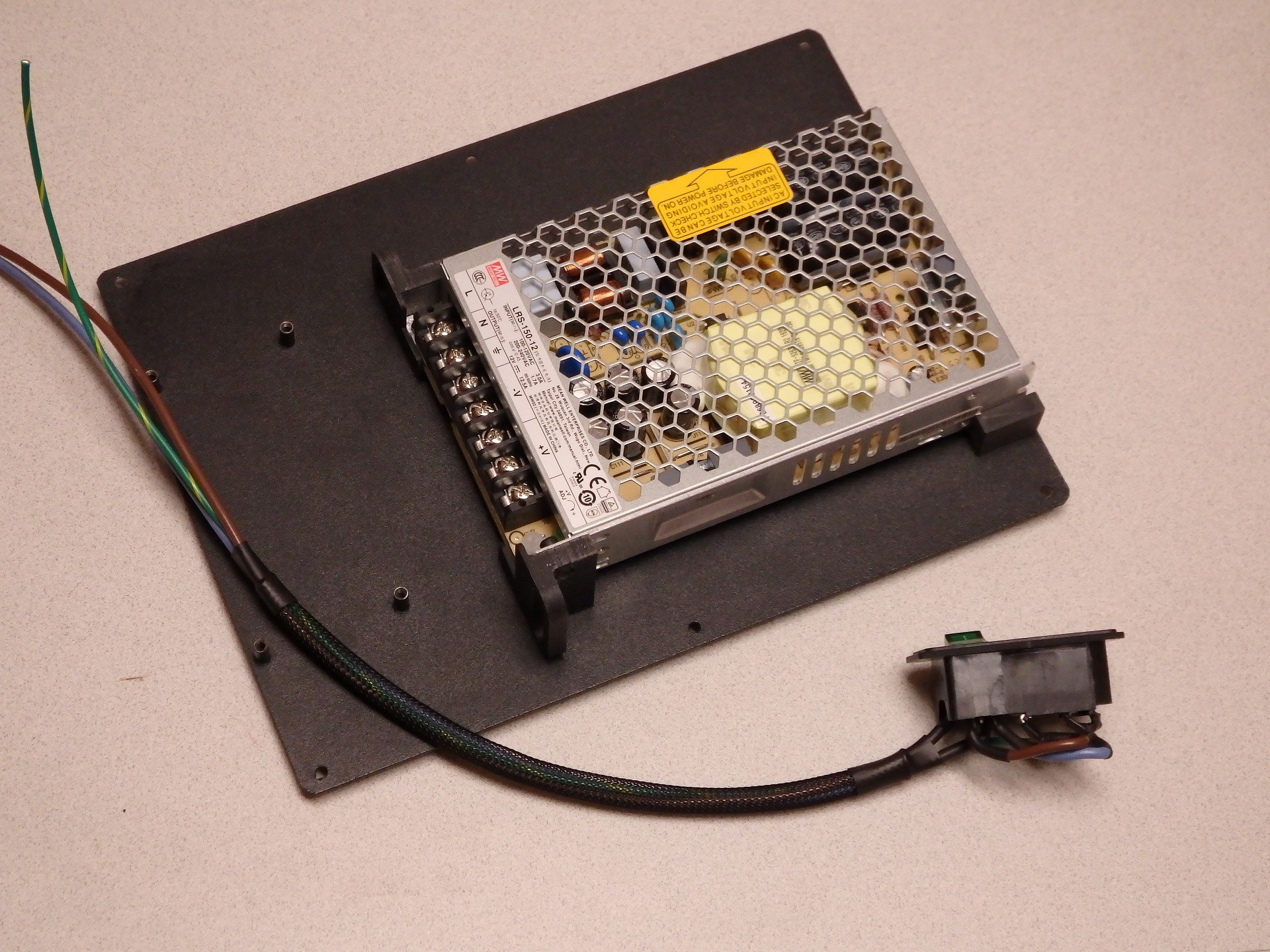
I hit the interwebs and tried to find a power supply that was small enough to fit inside the Mini, but had better specs than the stock supply. I wanted something with more current, so I could further mod the Mini and not run into power supply loading issues. The stock power supply is supposed to provide 10A of power at 12VDC, so the stock supply should be rated for 120 Watts (10A * 12V = 120W). By picking a higher capacity supply I would also be running it below spec and it should stay cooler as well. I settled on using a Meanwell LRS-150-12 supply. These are 150W at 12VDC, and sell for about $20 online, and my measurements indicated it would fit inside the Mini case.
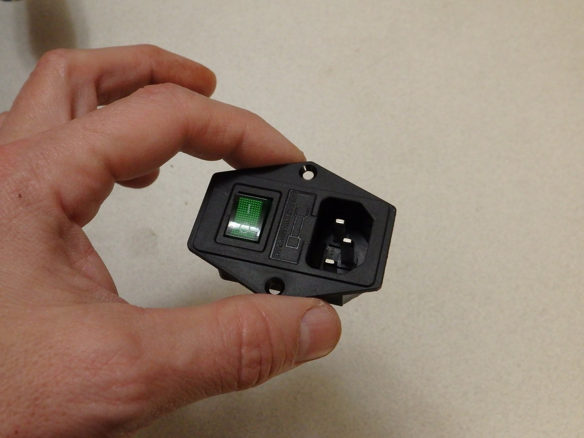
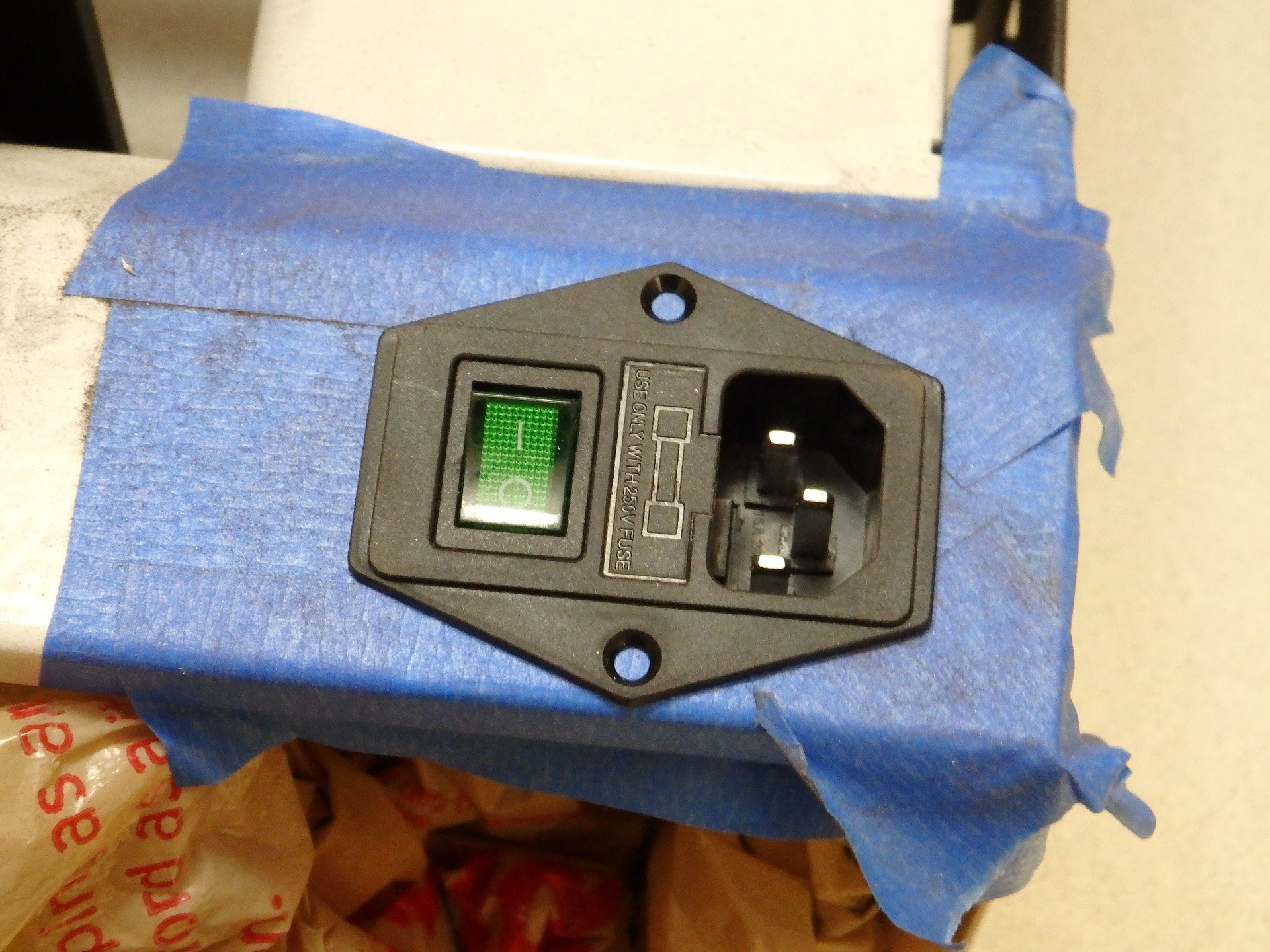
While I was messing around with the power supply, I decided I would add a switch and a fuse and when I was looking around I came across a nice little IEC320 C14 Power Socket with Illuminated Switch Fuse Holder on Amazon (Search for the part by name and several sellers come up). I did some measurements, and determined that the socket would fit in a hole that completely covered the existing power input and switch holes in the Mini, so it would look like it was a factory installed component.
![]()
When I got the power supply I test fit it inside, and there was plenty of room. However, the supply covered the vents in the bottom of the case. The height of the supply is short enough that I decided to raise it up on metal threaded standoffs so that it would have ventilation under the supply. The problem with this idea is that there are only two mounting screw holes on the bottom of the supply. The holes are on opposite corners, so they could hold it in place, but it seemed a little unstable for my tastes. I ditched the standoffs in favor of some printed mounting brackets that would hold it in more than two points.
![]()
While my mounting brackets were printing, I wired up the input wiring. Based on the test fitting of the power supply, I opted to directly solder the power wiring to the lugs on the power socket and switch, instead of using crimp on spade terminals. This allowed me to better insulate the wiring with heat shrink, and bend the lugs over to provide extra clearance behind the power supply. This is how the power is wired for use with US 120VAC power.
![]()
My printed mounting brackets hold the supply on the bottom edge and side edges and provide attachment on all four corners, I also added some wire harness guide loops to assist in routing the wiring inside the Mini. I tweaked the size of the brackets for maximum clearance for the cooling air to come in through the vent holes below the power supply, and split the one bracket into two sections so there would be an air passage to flow from the vent to the CPU board. You can download these bracket files from our Thingiverse page at the following link: http://www.thingiverse.com/thing:1881464 (see that page for printing instructions)
![]()
When installed, they held the power supply firmly in place and had plenty of air gap over the vents to allow cooling air flow under the supply. I turned out great. The edge of the supply with the screw terminals just fits under the Z stepper motor, so I had to be careful where I located the supply mounting. In the end I found a location I was happy with.
![]()
Cutting a hole for the Power Socket was simple. I just used a Dremel tool with a cutting wheel. The steel was a lot thicker than I thought it would be, but working slowly and putting tape over the areas I wanted to keep pristine helped. I also stuffed plastic bags inside the Mini case, to prevent the dust and shavings from getting on the mechanism or electronics.
![]()
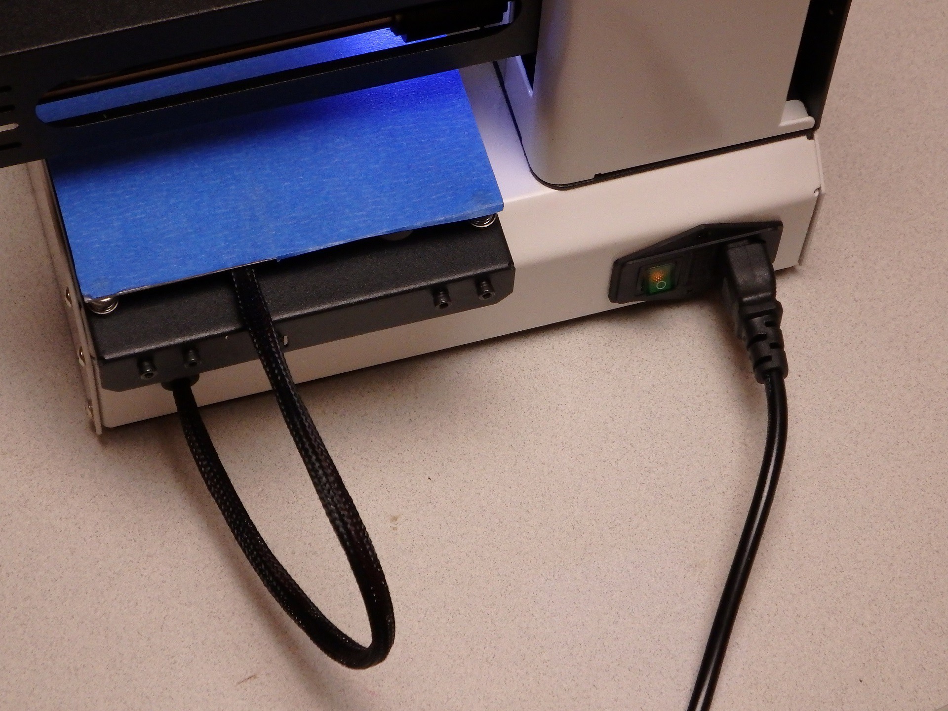
The sharp edges were cleaned up manually with a file and smoothed to the point I was happy they looked decent, then I test fit the Power Socket. The final bit of this work was finished up by drilling the mounting screw holes. I used some M3 flathead screws and nuts in the bracket to hold it in place.
![]()
When everything was buttoned up, the only thing I needed was a fuse for the Power Connector (It didn't come with one). I have seen where many people had the same issue with this connector and they ran out and ordered a fuse to match the current rating of their supply, but this is wrong and dangerous. A 10A 12V supply does not require a 10A fuse on the AC input side of the supply. You would use a 10A fuse if you were fusing the 12V lines. In the case of our Power Connector, the fuse is wired to the AC input, which has a significantly higher voltage, therefore the current needed is lower. I couldn't find the complete specs for the power supply, so I measured the AC current draw of the Mini with both heaters running and measured 2.6A on the AC input. I put a 3A fuse in the socket and it didn't blow. The inrush current of the power supply caused by turning the switch on and off didn't blow it either, so I think I have a good value for the fuse.
![]()
I'm really pleased with the way it turned out. I just completed a 56 hour long print with the Mini, and it worked flawlessly. I really like this mod. It did kind of blow up my budget on this project because it ended up costing about $25, but I think it looks really nice, and of course it frees up space on the desk by eliminating the bulky external supply. The added safety of the fuse is also a bonus. let me know what you think of this mod in the comments section. Enjoy!
Stay tuned for more mods!
-
Don't go wobbly on me now!
01/14/2017 at 23:02 • 0 comments![]() Several people in the Facebook Group for the Monoprice Select Mini have experienced severe issues with wobble in their Z-axis that is not cured by stabilizing the rails. I have seen several people who have observed that their print quality suffers because the stock coupler between the Z-Axis Stepper Motor and the Threaded Rod is not aligning the two shafts properly, or the grub screw is shifting the rod to one side. I decided to make a replacement for the coupler that forces the threaded rod into perfect alignment with the motor shaft. Get the file on my Thingiverse page: http://www.thingiverse.com/thing:2038369
Several people in the Facebook Group for the Monoprice Select Mini have experienced severe issues with wobble in their Z-axis that is not cured by stabilizing the rails. I have seen several people who have observed that their print quality suffers because the stock coupler between the Z-Axis Stepper Motor and the Threaded Rod is not aligning the two shafts properly, or the grub screw is shifting the rod to one side. I decided to make a replacement for the coupler that forces the threaded rod into perfect alignment with the motor shaft. Get the file on my Thingiverse page: http://www.thingiverse.com/thing:2038369![]() Here is the coupler which I designed. On one side it has threads for the 4mmx0.7 Threaded Rod, and the other side has a hole to accept the 3mm Motor Shaft. Three clamping surfaces per side will be used to hold the coupler firmly in place and force the two shafts into perfect alignment.
Here is the coupler which I designed. On one side it has threads for the 4mmx0.7 Threaded Rod, and the other side has a hole to accept the 3mm Motor Shaft. Three clamping surfaces per side will be used to hold the coupler firmly in place and force the two shafts into perfect alignment.![]() This piece will print perfectly fine with no supports and oriented so that the threaded hole is facing up. Please print with thick walls and a decent fill. I used 4 perimeters and 20% infill for this one. I do not think the plastic type is important because this part is not subjected to heat.
This piece will print perfectly fine with no supports and oriented so that the threaded hole is facing up. Please print with thick walls and a decent fill. I used 4 perimeters and 20% infill for this one. I do not think the plastic type is important because this part is not subjected to heat.![]() Installation is very simple: Begin by removing the six screws that hold the black metal bottom to the mini and pull the bottom off the printer.
Installation is very simple: Begin by removing the six screws that hold the black metal bottom to the mini and pull the bottom off the printer.![]()
Six more screws hold the metal cover to the back of the tower, three on top and three inside the base of the Mini. These screws may have small washers on them, so keep track of the screws with washers and where they were located.
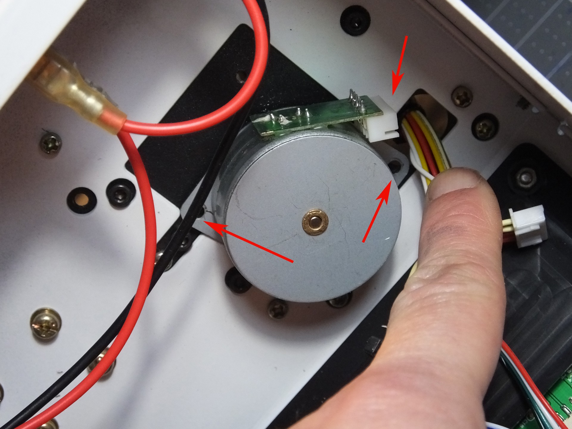
![]() Remove the two screws holding the Z-Axis Stepper Motor to the underside of the tower. Also unplug the cable while you're in there. Note the position of the connector on the motor where the wires were plugged in. When you put the printer back together, you have a 50% chance of facing this in the wrong direction, unless you make a note this position now.
Remove the two screws holding the Z-Axis Stepper Motor to the underside of the tower. Also unplug the cable while you're in there. Note the position of the connector on the motor where the wires were plugged in. When you put the printer back together, you have a 50% chance of facing this in the wrong direction, unless you make a note this position now.![]() Spin the Threaded Rod to unscrew it from the Gantry. If you are reading these instructions before you began working then you get a bonus! When you begin work use the move menu to raise the Gantry all the way to the top before tearing down the printer. It will save you a lot of spinning of the Threaded Rod in this step here.
Spin the Threaded Rod to unscrew it from the Gantry. If you are reading these instructions before you began working then you get a bonus! When you begin work use the move menu to raise the Gantry all the way to the top before tearing down the printer. It will save you a lot of spinning of the Threaded Rod in this step here.![]()
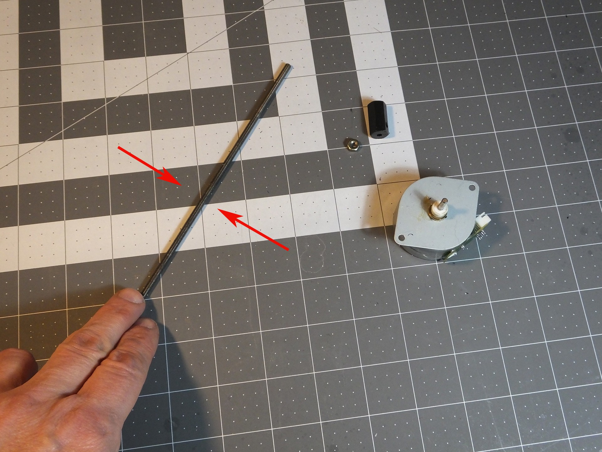
When you've unscrewed the Threaded Rod from the Gantry, it will come right off with the Stepper Motor. You need to remove the factory coupler from the Threaded Rod and the Stepper Motor, by loosening the grub screw or screws in the side of the coupler. There are often locked in place with a threadlocker, so use a flame from a lighter to heat the coupler very hot and the threads should come loose. Just be careful not to touch the hot metal. The coupler and the locking nut on top should come right off with a couple of wrenches now.
![]()
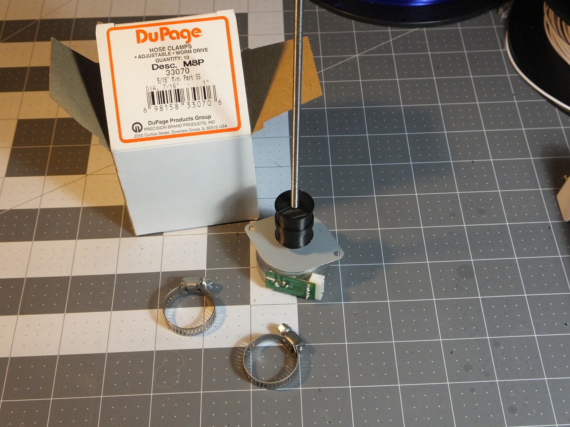
Roll the Threaded Rod on a perfectly flat surface and look to see if it is warped or bent. If it is, you can try to straighten it by hand until it rolls perfectly, or obtain a replacement part.![]() Push the unthreaded side of the New Coupler on the Motor Shaft until it just touches the spacers on the shaft. If you don't have spacers, don't go any closer to the motor than about 5mm. Then, thread the Threaded Rod into the threaded side of the New Coupler, and tighten it until it reaches the bottom of the hole. At this point you want to get a pair of Hose Clamps ready. The Hose Clamps should fit a 1" pipe and have a 5/16" wide band. Slightly smaller clamps should fit as well. Just prepare them by opening them up wide enough to fit over the New Coupler easily. DO NOT INSTALL THEM YET. If you do, you won't get the Stepper Motor back on.
Push the unthreaded side of the New Coupler on the Motor Shaft until it just touches the spacers on the shaft. If you don't have spacers, don't go any closer to the motor than about 5mm. Then, thread the Threaded Rod into the threaded side of the New Coupler, and tighten it until it reaches the bottom of the hole. At this point you want to get a pair of Hose Clamps ready. The Hose Clamps should fit a 1" pipe and have a 5/16" wide band. Slightly smaller clamps should fit as well. Just prepare them by opening them up wide enough to fit over the New Coupler easily. DO NOT INSTALL THEM YET. If you do, you won't get the Stepper Motor back on.![]() Now, insert the Threaded Rod through the hole and slide the Hose Clamps over the rod before you start threading it back into the Gantry where you removed it. Keep screwing the Threaded Rod into the Gantry until you can seat the Stepper Motor back where it belongs and screw it back in place, making note to get the connector back in the right position to reach the connector on the wiring harness.
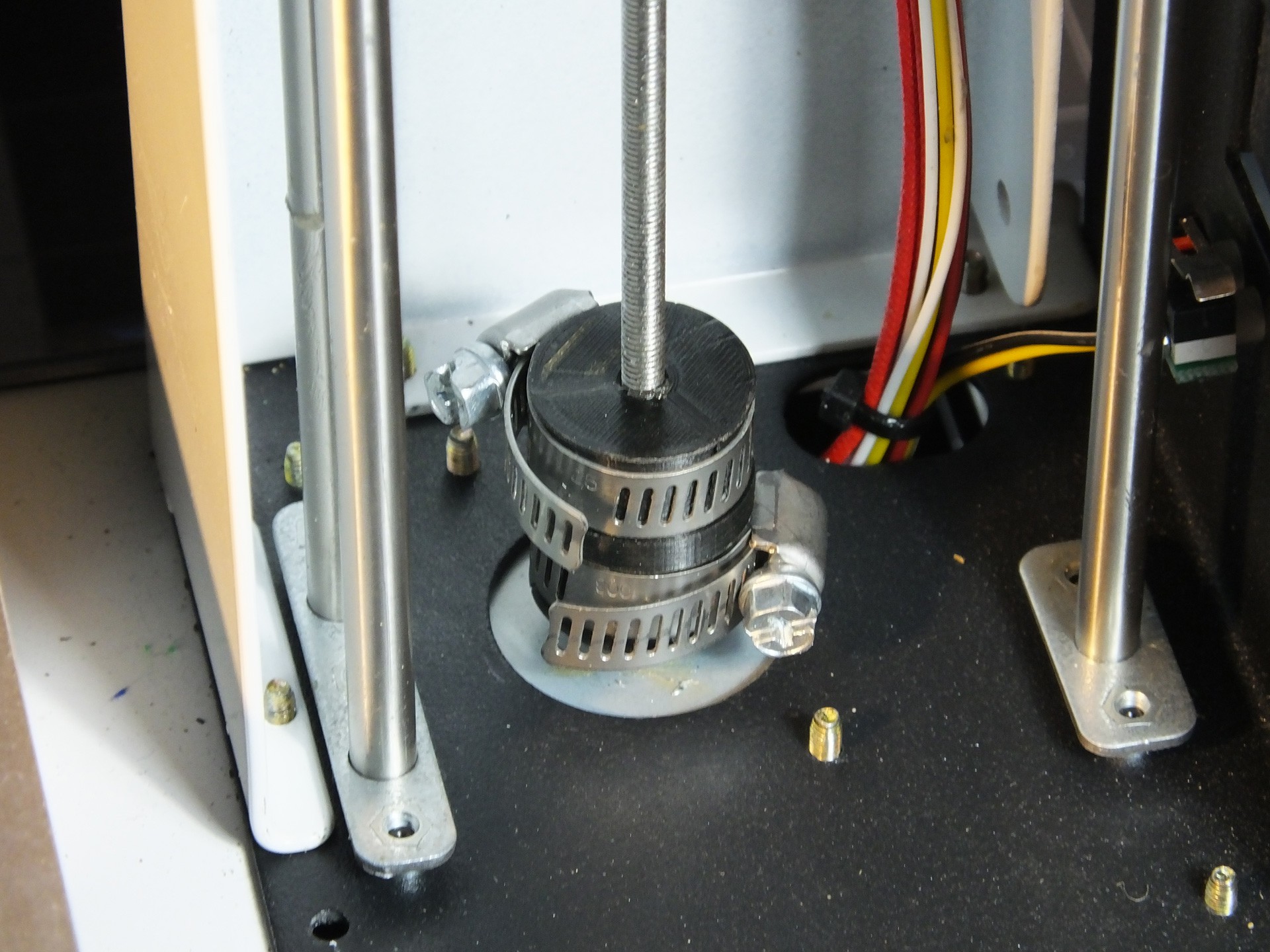
Now, insert the Threaded Rod through the hole and slide the Hose Clamps over the rod before you start threading it back into the Gantry where you removed it. Keep screwing the Threaded Rod into the Gantry until you can seat the Stepper Motor back where it belongs and screw it back in place, making note to get the connector back in the right position to reach the connector on the wiring harness.![]() Now you can slide the Hose Clamps down into the grooves in the New Coupler and tighten them up, to secure the Threaded Rod and Z-Axis Motor Shaft in perfect alignment.
Now you can slide the Hose Clamps down into the grooves in the New Coupler and tighten them up, to secure the Threaded Rod and Z-Axis Motor Shaft in perfect alignment.Check that the clamps don't interfere with the wiring inside the tower. If you think they may snag, you can cover the clamps with Electrical Tape to prevent them from catching the wiring.
Reinstall the rear cover of the tower, and then put the bottom cover back on the printer.
This upgrade cost me about $1.00 total, for two hose clamps. That's it!
Happy Printing!
-
Keeping the X-Axis Belt from Twisting
01/20/2017 at 05:17 • 4 commentsOver on the Facebook Group for the Mini, Brian Corbino started a flurry of activity when he posted a description of how he went about changing the plastic pulleys and cheap belts in the Mini with aluminum pulleys and GT2 belts. Quite a number of people were interested in this project, and have been having a lot of success with this upgrade.
Seeing how many people are swapping the pulleys reminded me of something I wanted to fix on the Mini for a long time but never got around to it. What I'm talking about is the way the pulley bracket for the X-Axis idler pulley is fastened to the end of the gantry with a single screw on the center point of the bracket. This means that the pulley is completely free to twist out of alignment when you tighten the screw.
![]() See how the pulley bracket is twisted? This is really annoying, and every time you install this pulley you have to mess around and try and get it straight by hand. Because this annoys me, I created an Alignment Clip that goes between the pulley bracket and the plastic channel where the pulley sits, which keeps the pulley at a perfect right angle to the rods, which will make the belt perfectly flat and level.
See how the pulley bracket is twisted? This is really annoying, and every time you install this pulley you have to mess around and try and get it straight by hand. Because this annoys me, I created an Alignment Clip that goes between the pulley bracket and the plastic channel where the pulley sits, which keeps the pulley at a perfect right angle to the rods, which will make the belt perfectly flat and level.![]() Here is what the Alignment Clip looks like before it is installed. To install the alignment bracket, you can clip it over the pulley bracket and insert it into the channel in the end of the gantry, or put the Alignment Clip in the channel first and then install the pulley bracket. If you want to print your very own Alignment Clip, you can get the model from my Thingiverse Page: http://www.thingiverse.com/thing:2049820
Here is what the Alignment Clip looks like before it is installed. To install the alignment bracket, you can clip it over the pulley bracket and insert it into the channel in the end of the gantry, or put the Alignment Clip in the channel first and then install the pulley bracket. If you want to print your very own Alignment Clip, you can get the model from my Thingiverse Page: http://www.thingiverse.com/thing:2049820![]() Note the orientation of the Alignment clip. It should only clip on one way and should center itself once you install it on the gantry. It should fit snugly in the channel, and prevent the pulley from twisting.
Note the orientation of the Alignment clip. It should only clip on one way and should center itself once you install it on the gantry. It should fit snugly in the channel, and prevent the pulley from twisting.![]() Here's the "After" photo, showing how nice and straight the pulley is now that it can't twist. Does this affect print quality or the life of the belt and pulley? I'm not sure. However, it takes only a couple of minutes to print, and makes working on the belt and pulley totally effortless. You don't have to fuss with the alignment of the pulley by hand any longer.
Here's the "After" photo, showing how nice and straight the pulley is now that it can't twist. Does this affect print quality or the life of the belt and pulley? I'm not sure. However, it takes only a couple of minutes to print, and makes working on the belt and pulley totally effortless. You don't have to fuss with the alignment of the pulley by hand any longer.
Monoprice Select Mini Maximum 3D Printer Mods
Low/zero cost upgrades for the Monoprice Select Mini 3D Printer.


 This is that the Part Cooling Fan looks like when it is removed from the E3DV6 Mount. Notice that it has a JST style connector so that I can swap in different fans and LED lights in the future as I design new styles.
 The outlet of this nozzle directs all of the air flow directly on the extruded plastic that has just exited the nozzle. This is intended for improving overhangs and bridges. You can also see the LEDs that illuminate the print beside the outlet.
 The files and installation instructions for this setup are now available on our Thingiverse Page. To download these files, please go to:
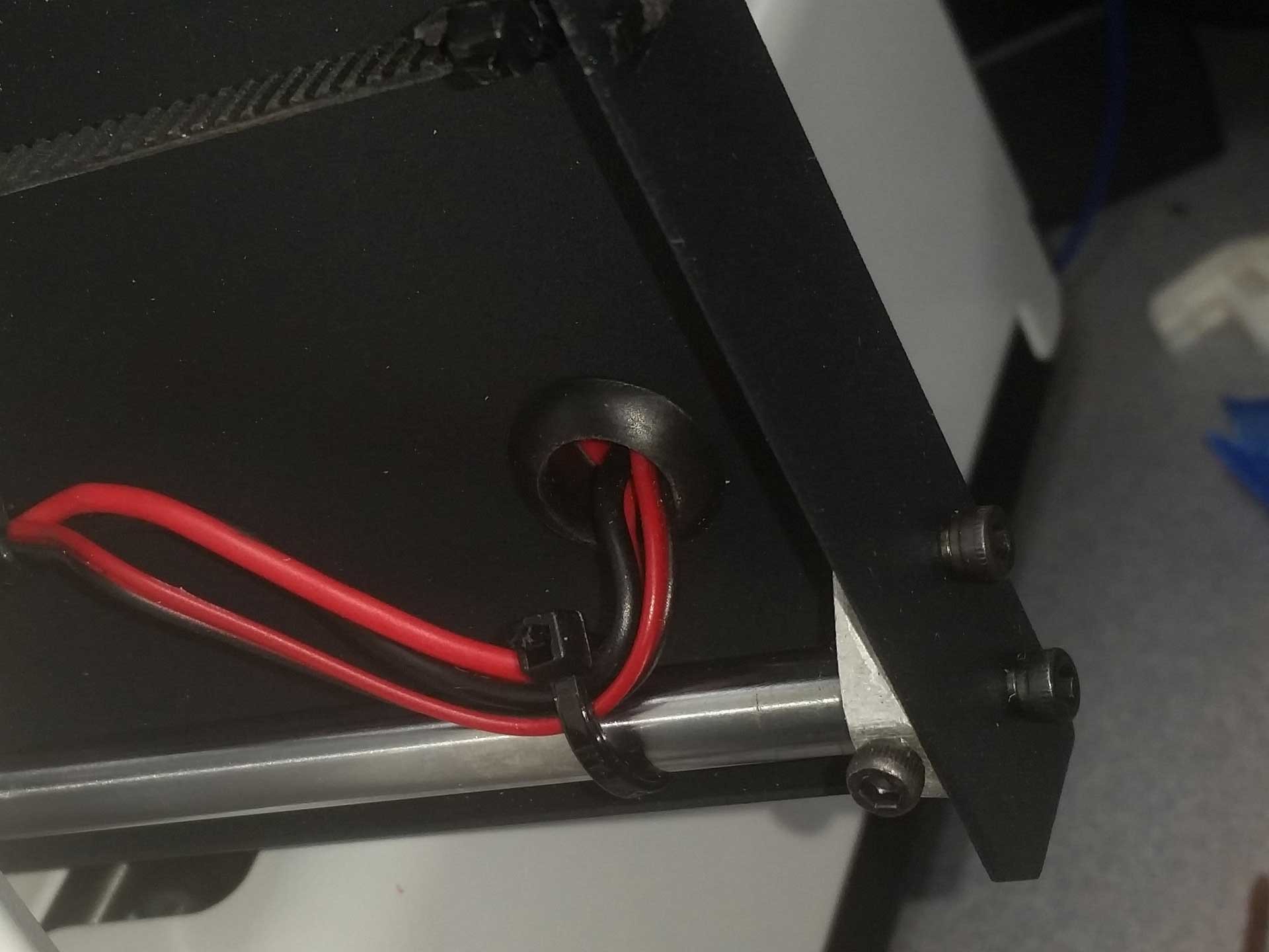 Check out the video below and see if you can spot the issue before I explain it and discuss my solution.
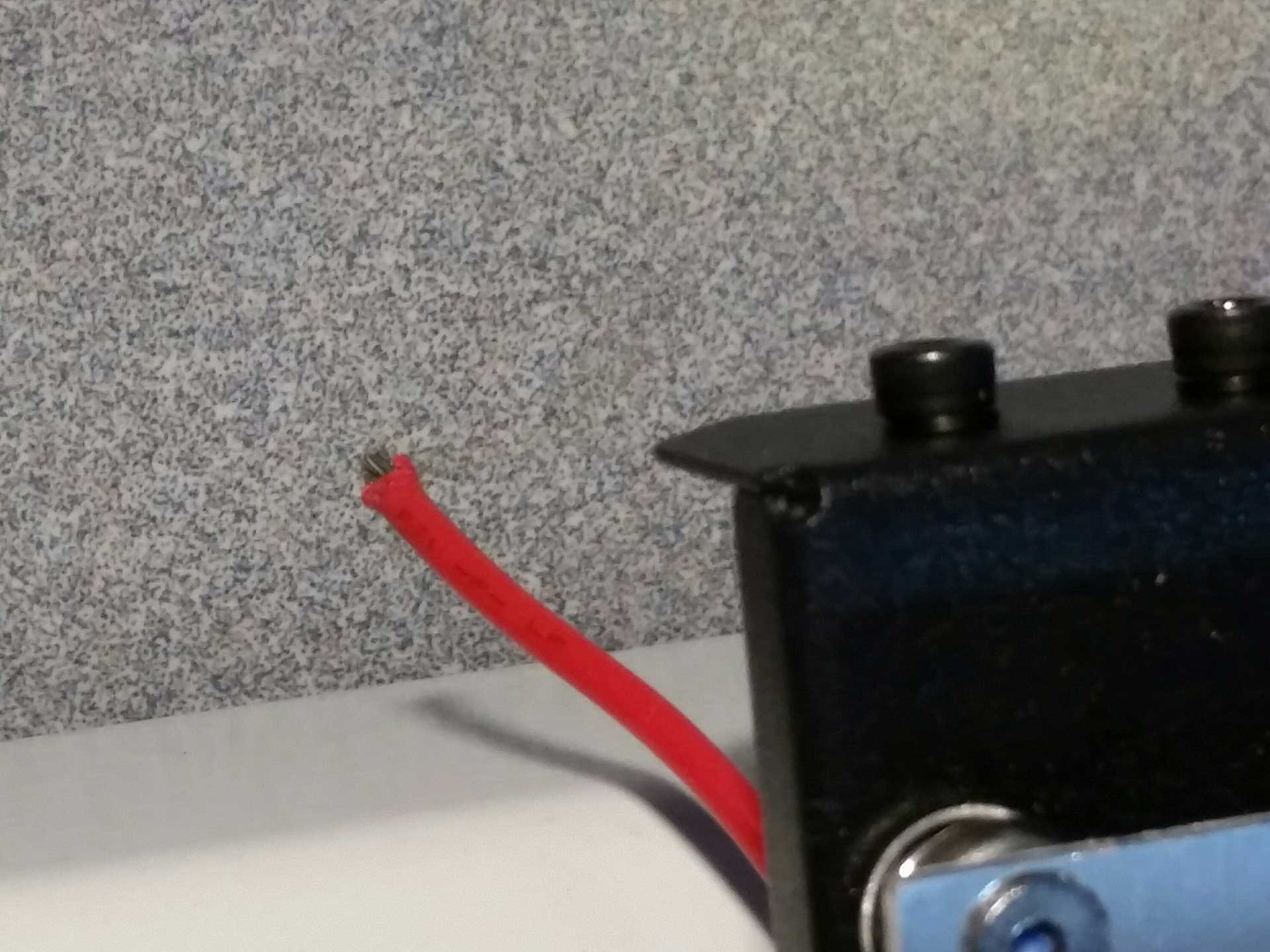
 My solution was to replace the heated bed wiring with better quality wiring and route it so that there would be no stress on the wires and no interference with any of the moving parts. For the wiring, I chose to use silicone jacketed wire which I had on hand for my rocket and quadrotor experiments, which I purchased in bulk from Hobbyking. I probably only used a dollar or so of the wire if I were to buy it separately.
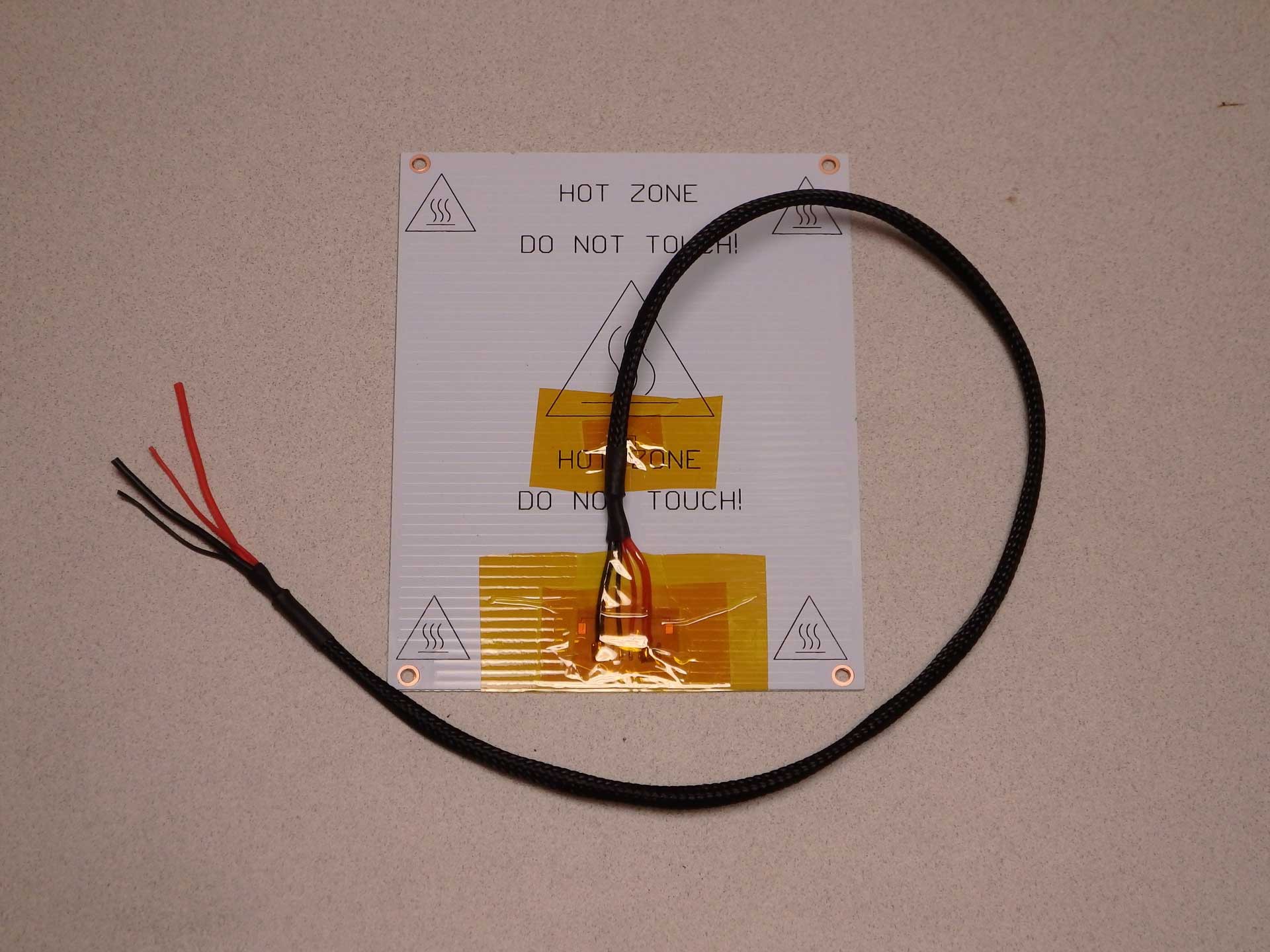
 To solve the original Y-axis belt rubbing problem, I re-routed the heated bed wiring through the slot in the Z-axis tower. The gantry never lowered enough to interfere with the wiring, and the new cable routing solved all the issues with the belt. The wire actually moves very little ones it is not confined under the bed. This wire configuration should be standard on the Mini.
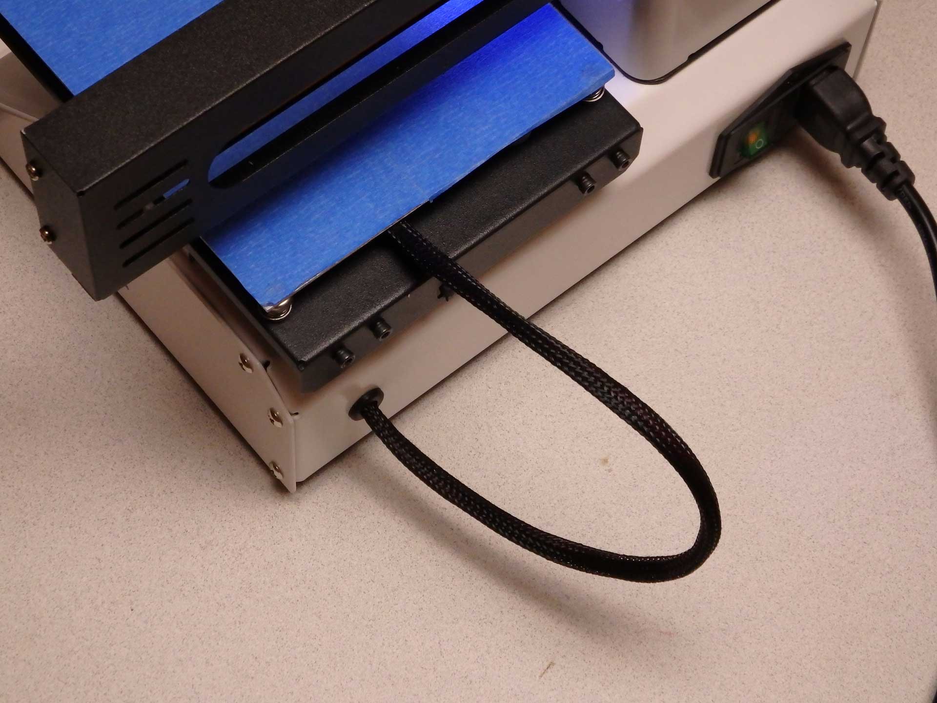 Ultimately, I decided I didn't like the length of the heated bed wires, so I decided to make a hole in the back of the printer and transplant the rubber grommet from the bed to the rear of the printed, and feed the wires directly out the back of the printer below the bed. I like this approach because I was able to make the wiring a lot shorter. This is even better and should really be the way the printers are built from the factory (even better than my last suggestion).
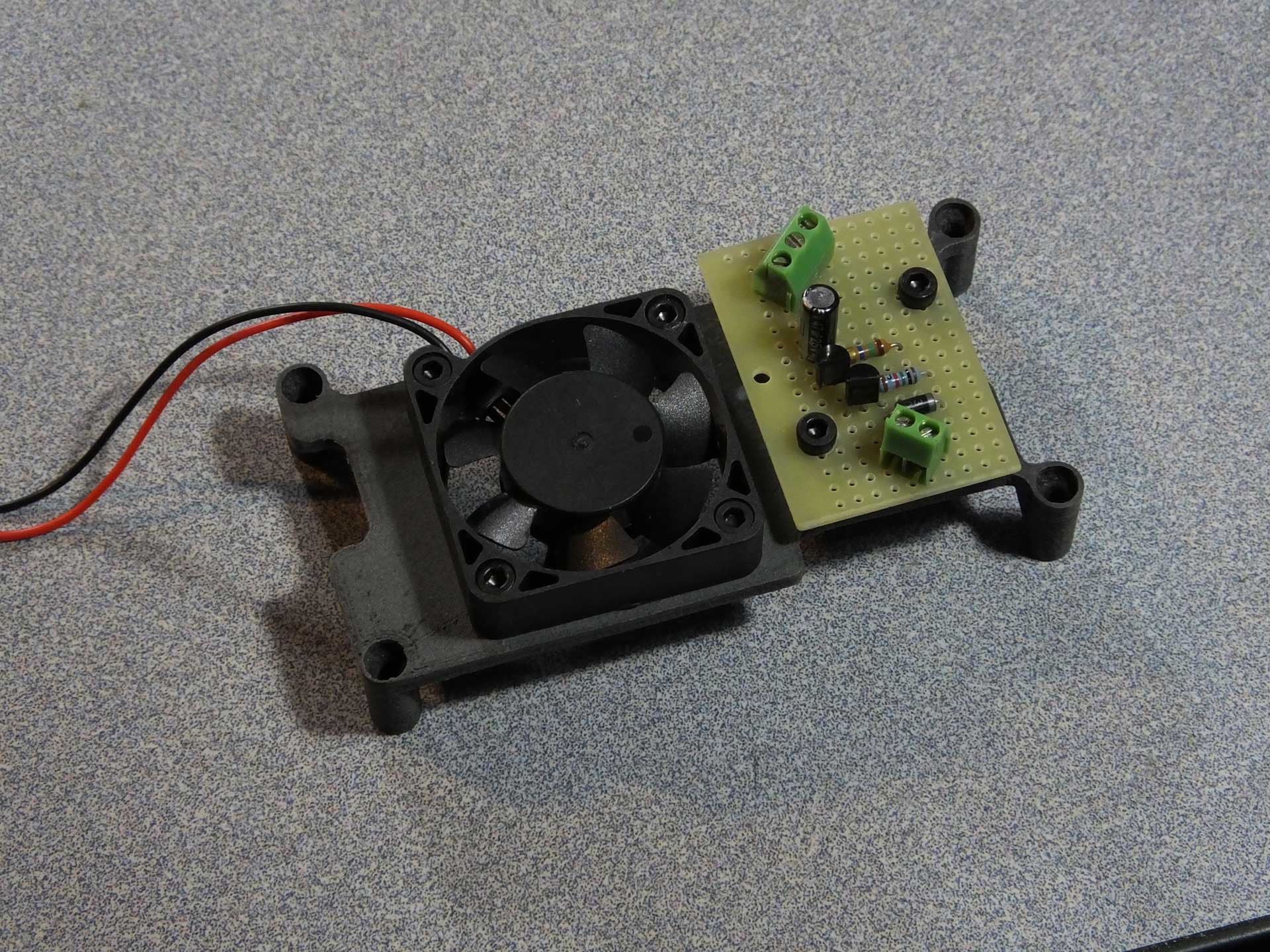
 The operation of the circuit is quite simple: 12V is provided to the heater and the ground for the heater is connected by a FET on the control board, when the heater is turned on. We use this signal to monitor for the heater activity.
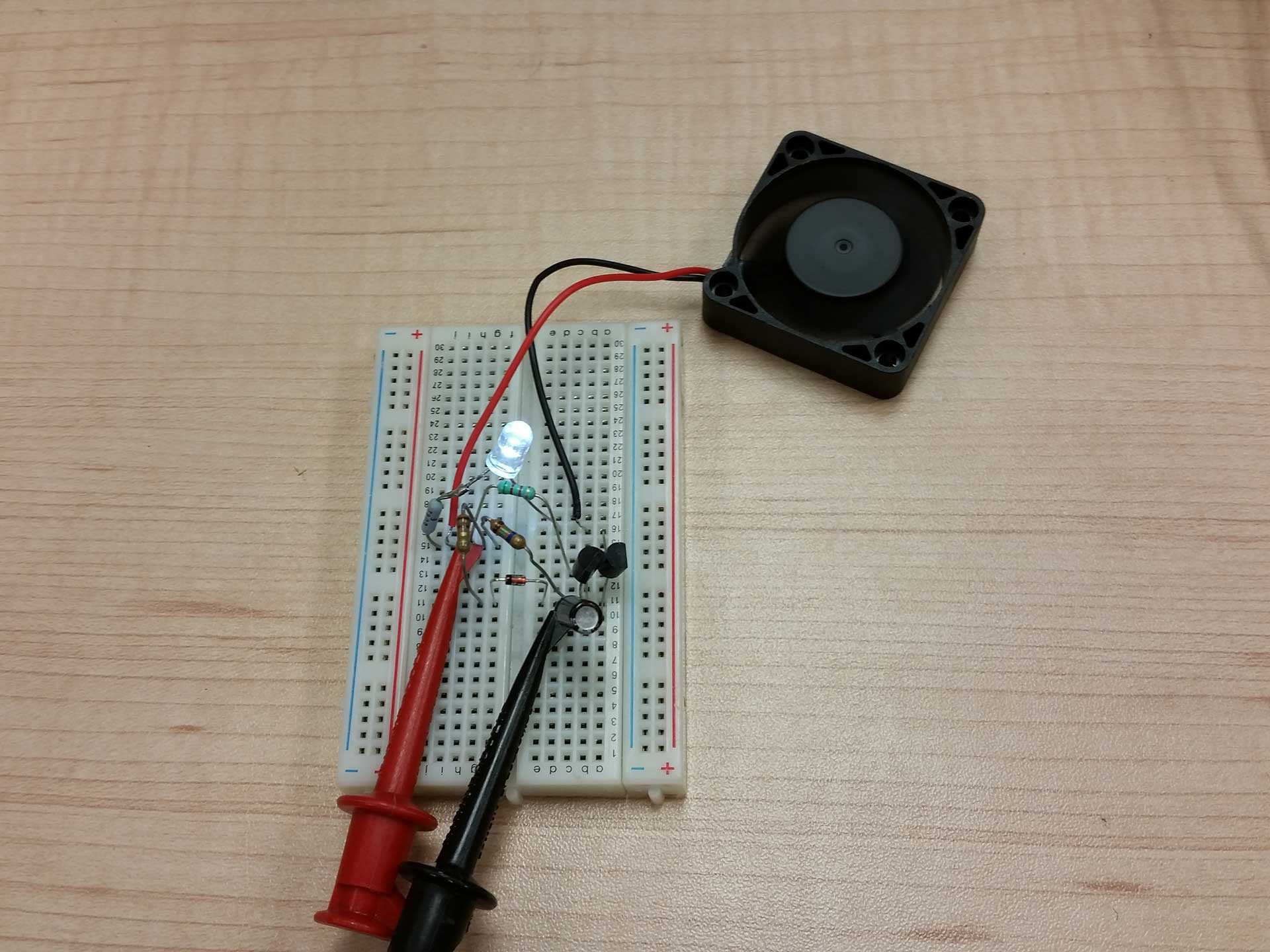 The circuit was mocked up and tested on a breadboard kit, using through-hole parts I had not touched in a few years. It was fun going back and doing this for a change.
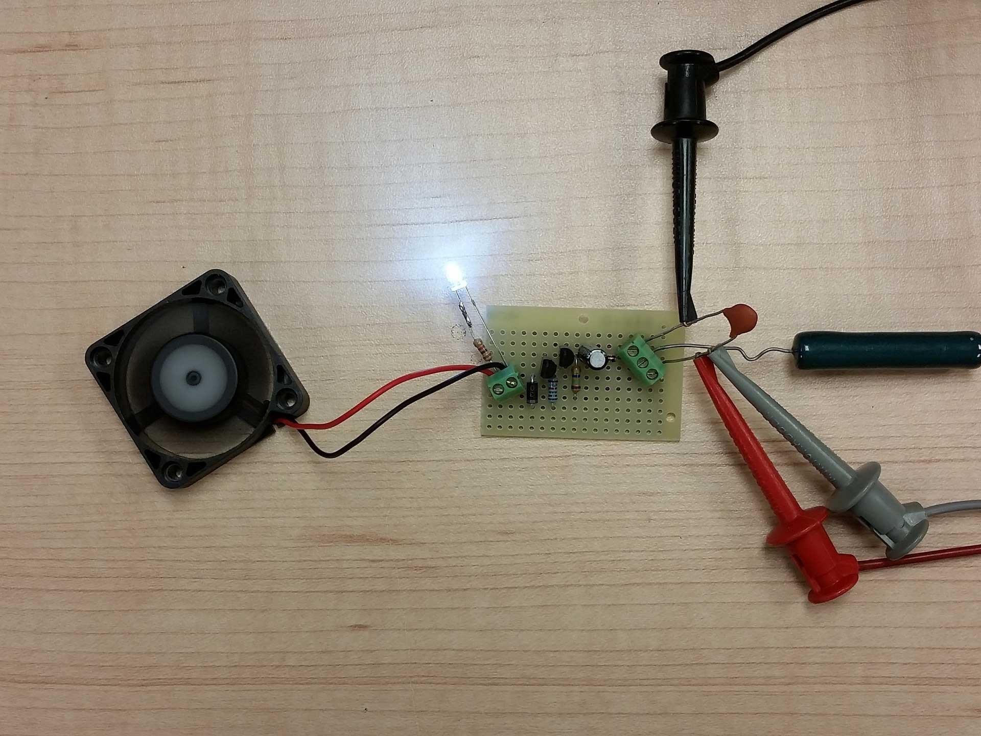 The circuit was then transplanted to some perf board for installation in my Select Mini. Above you can see where I used an old wire wound 10 ohm resistor to simulate the heater. Grounding the center terminal on the right simulates the pulsing of the heater ground on the Mini. Another thing you may notice is the small capacitor on the + and - power terminals. This has nothing to do with the circuit itself. It's just a neat trick that a very smart guy told me many years ago. The purpose of the capacitor is to provide a place to clip test leads on the power screw terminals. Instead of sticking paper clips or wires into the screw terminals, you insert a capacitor (of sufficient voltage rating for the supply). The trick is that the capacitor doesn't affect the circuit but provides a good place to clip the test leads and the body of the capacitor prevents the leads from moving around and shorting together as you handle the circuit. I always loved this trick.
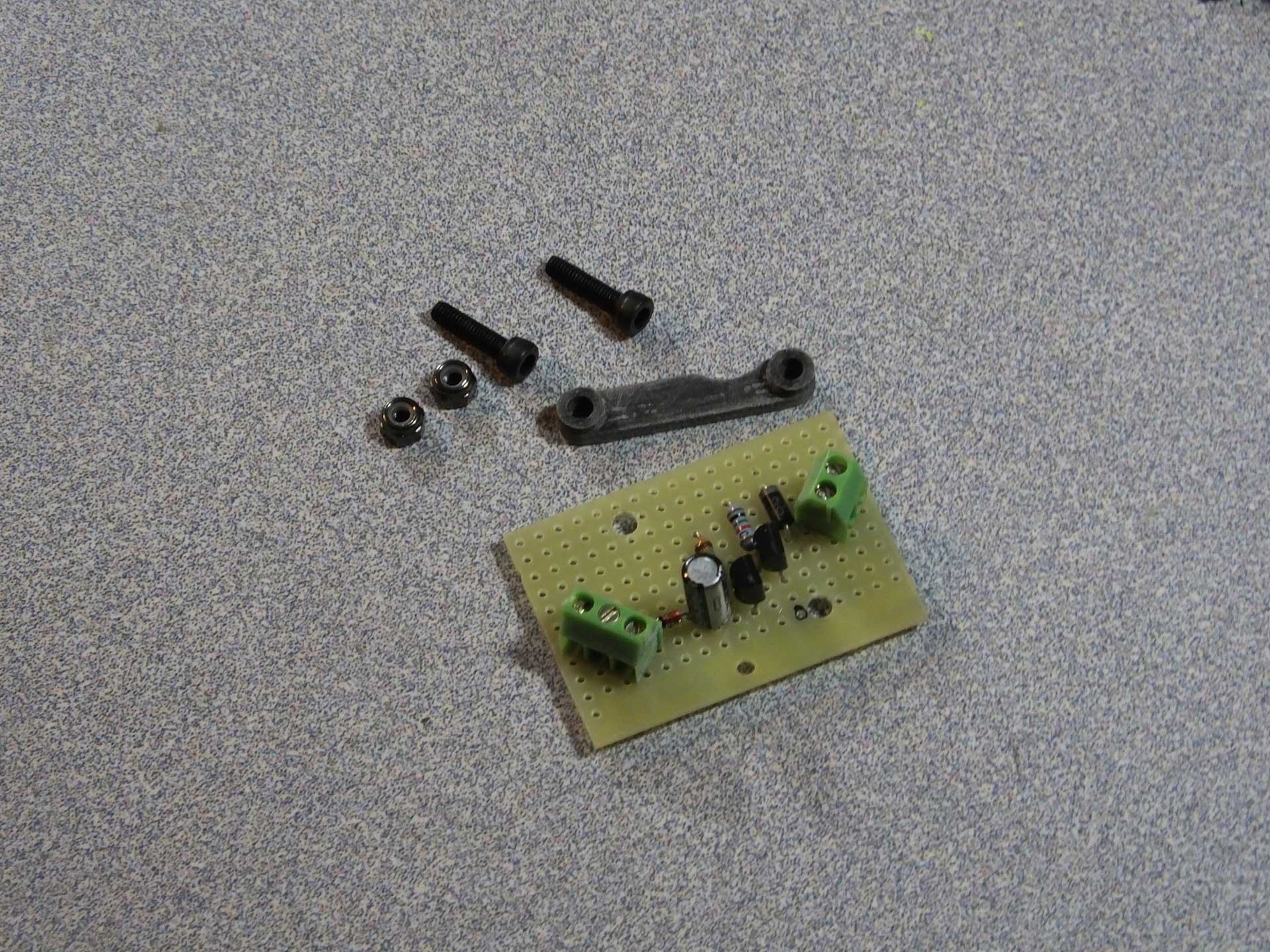 I printed a small support bracket for the PCB I made, which was designed to fit on the top of the 40mm cooling fan bracket which I designed for the control board inside the printer. The object files for these printed parts is located on our Thingiverse page. You can get them here:
 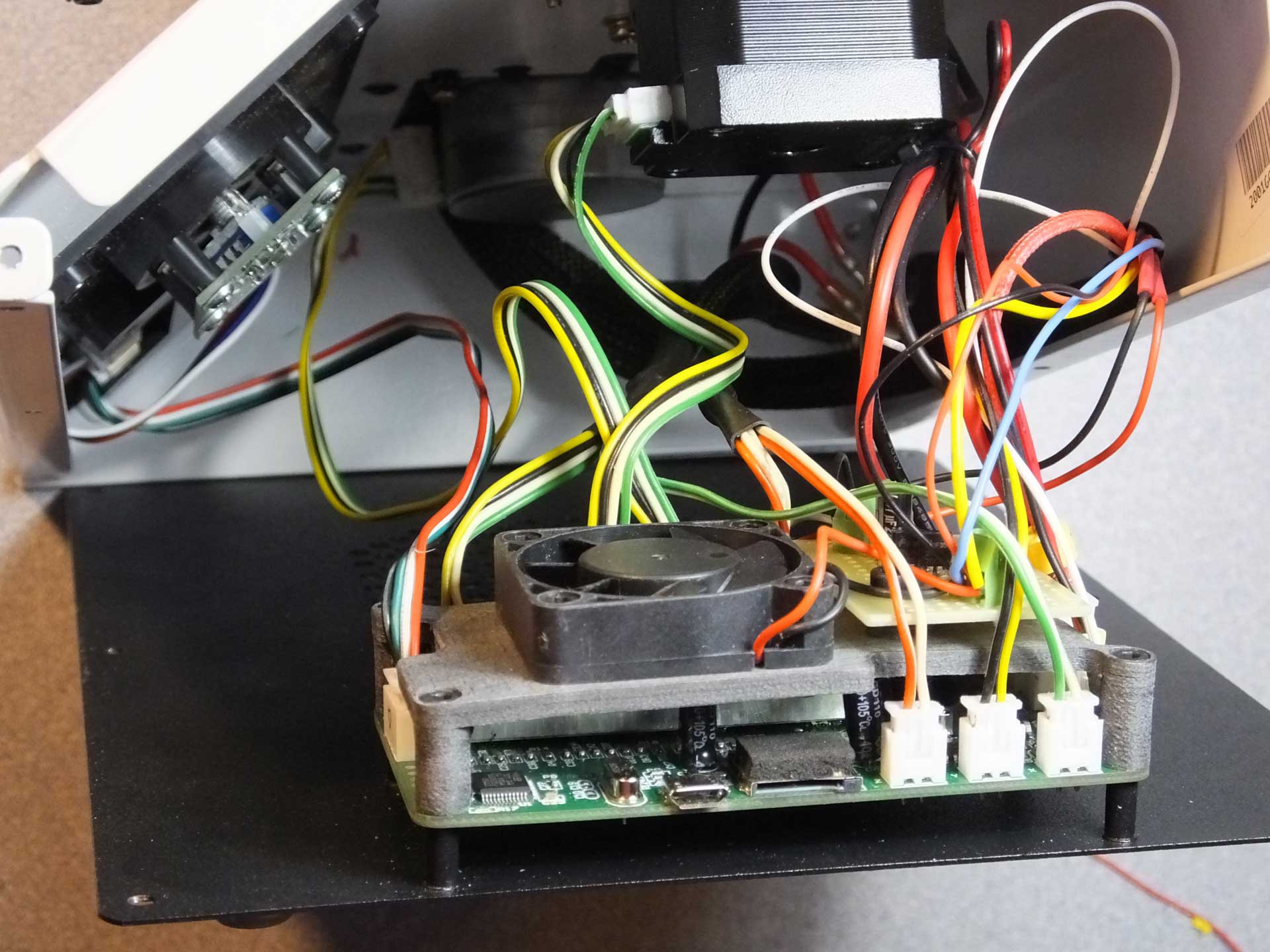 I did have to tap into the 12V power and the HEATER control signal coming from the control board, but I accomplished this by soldering some short wires to the underside of the control board to pick up the signals.


 Several people in the Facebook Group for the Monoprice Select Mini have experienced severe issues with wobble in their Z-axis that is not cured by stabilizing the rails. I have seen several people who have observed that their print quality suffers because the stock coupler between the Z-Axis Stepper Motor and the Threaded Rod is not aligning the two shafts properly, or the grub screw is shifting the rod to one side. I decided to make a replacement for the coupler that forces the threaded rod into perfect alignment with the motor shaft. Get the file on my Thingiverse page:
 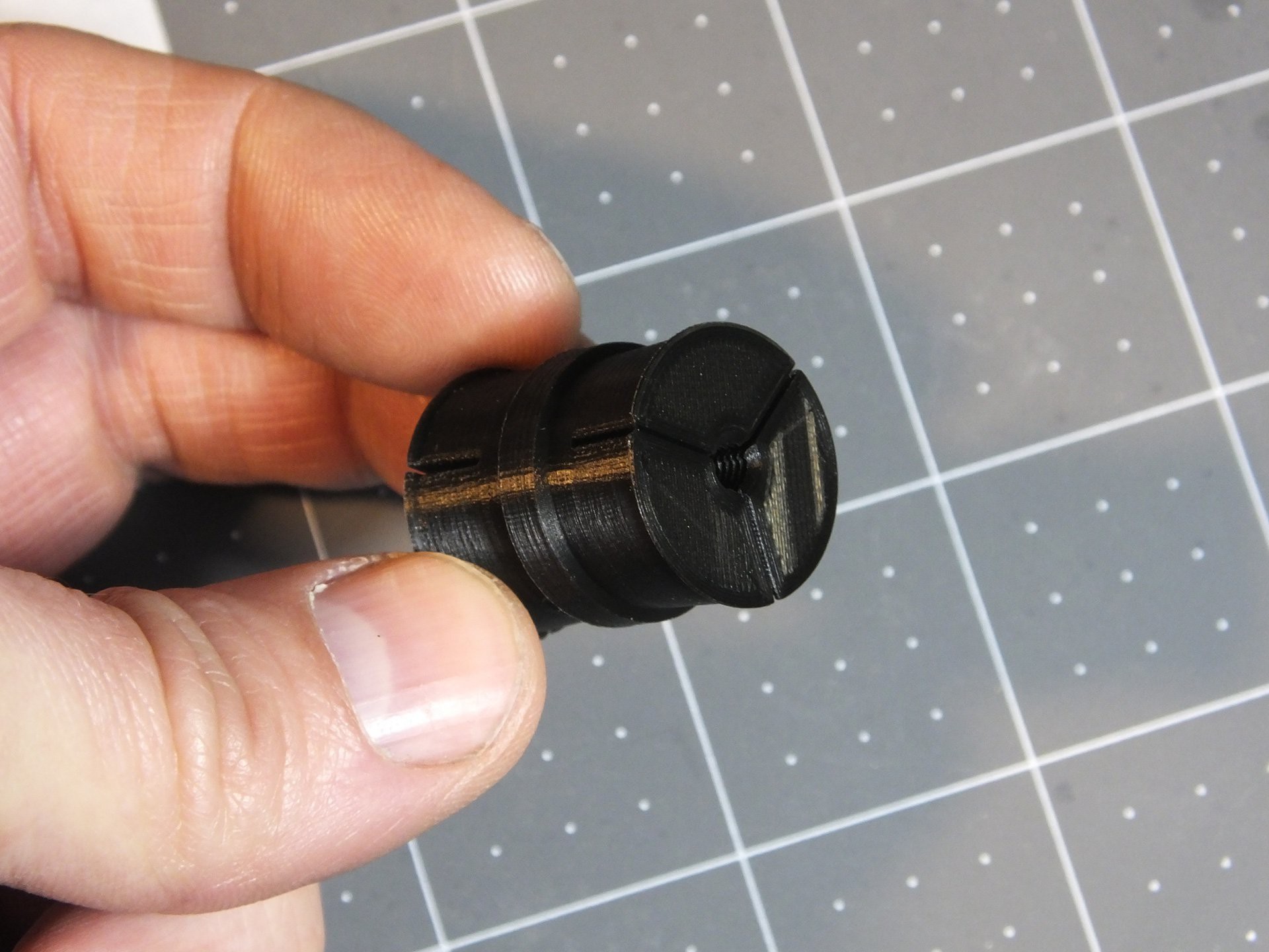 Here is the coupler which I designed. On one side it has threads for the 4mmx0.7 Threaded Rod, and the other side has a hole to accept the 3mm Motor Shaft. Three clamping surfaces per side will be used to hold the coupler firmly in place and force the two shafts into perfect alignment.
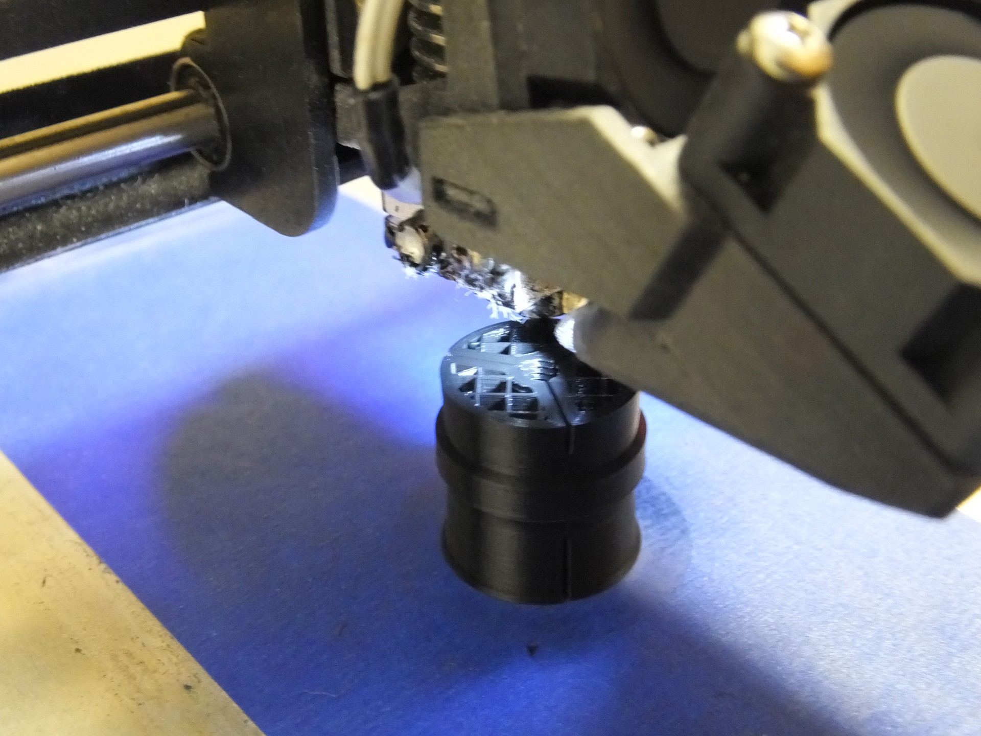 This piece will print perfectly fine with no supports and oriented so that the threaded hole is facing up. Please print with thick walls and a decent fill. I used 4 perimeters and 20% infill for this one. I do not think the plastic type is important because this part is not subjected to heat.
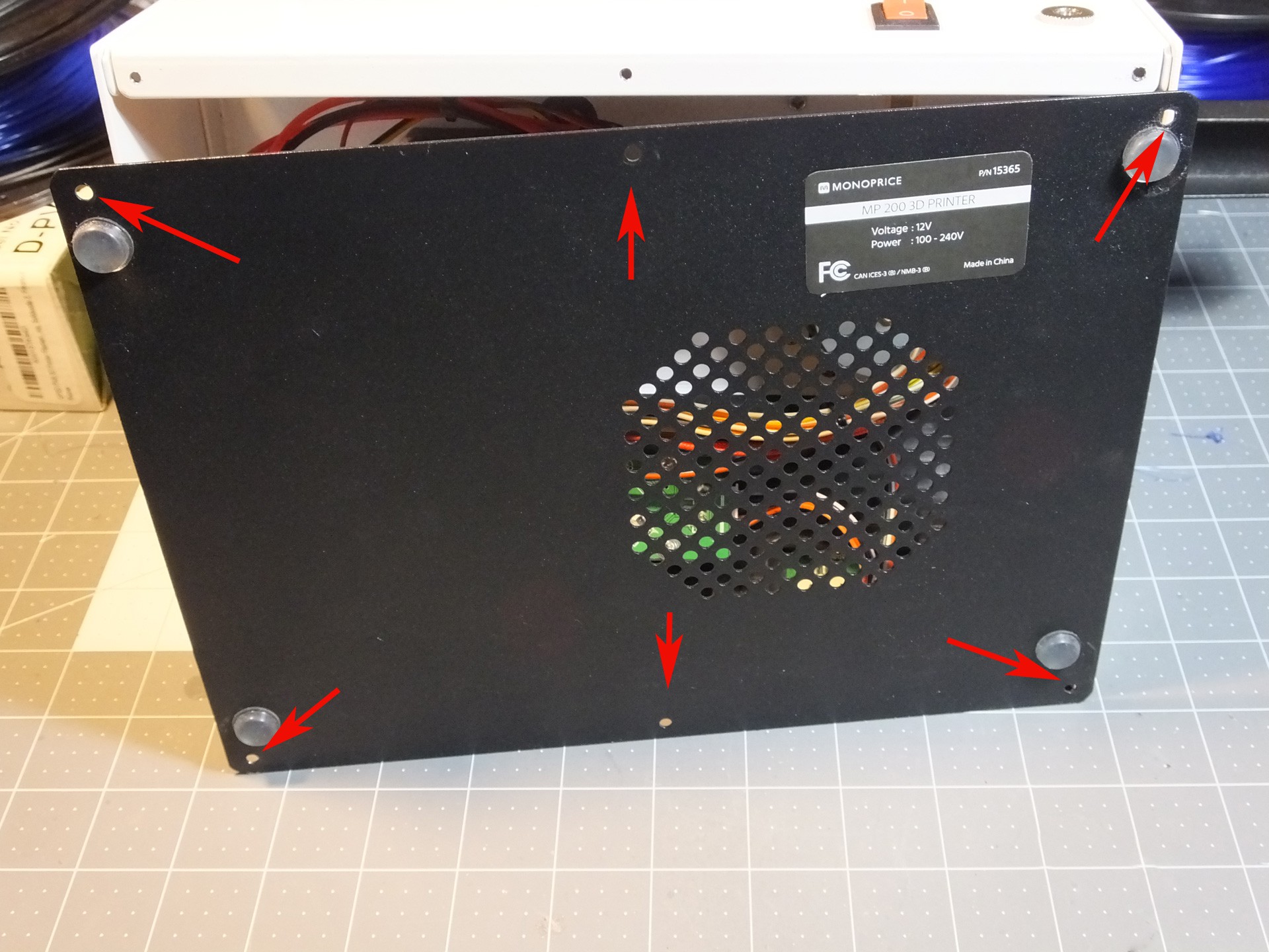 Installation is very simple: Begin by removing the six screws that hold the black metal bottom to the mini and pull the bottom off the printer.
 Remove the two screws holding the Z-Axis Stepper Motor to the underside of the tower. Also unplug the cable while you're in there. Note the position of the connector on the motor where the wires were plugged in. When you put the printer back together, you have a 50% chance of facing this in the wrong direction, unless you make a note this position now.
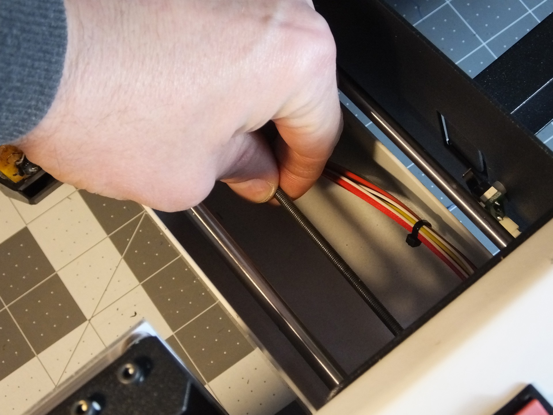 Spin the Threaded Rod to unscrew it from the Gantry. If you are reading these instructions before you began working then you get a bonus! When you begin work use the move menu to raise the Gantry all the way to the top before tearing down the printer. It will save you a lot of spinning of the Threaded Rod in this step here.
 Push the unthreaded side of the New Coupler on the Motor Shaft until it just touches the spacers on the shaft. If you don't have spacers, don't go any closer to the motor than about 5mm. Then, thread the Threaded Rod into the threaded side of the New Coupler, and tighten it until it reaches the bottom of the hole. At this point you want to get a pair of Hose Clamps ready. The Hose Clamps should fit a 1" pipe and have a 5/16" wide band. Slightly smaller clamps should fit as well. Just prepare them by opening them up wide enough to fit over the New Coupler easily. DO NOT INSTALL THEM YET. If you do, you won't get the Stepper Motor back on.
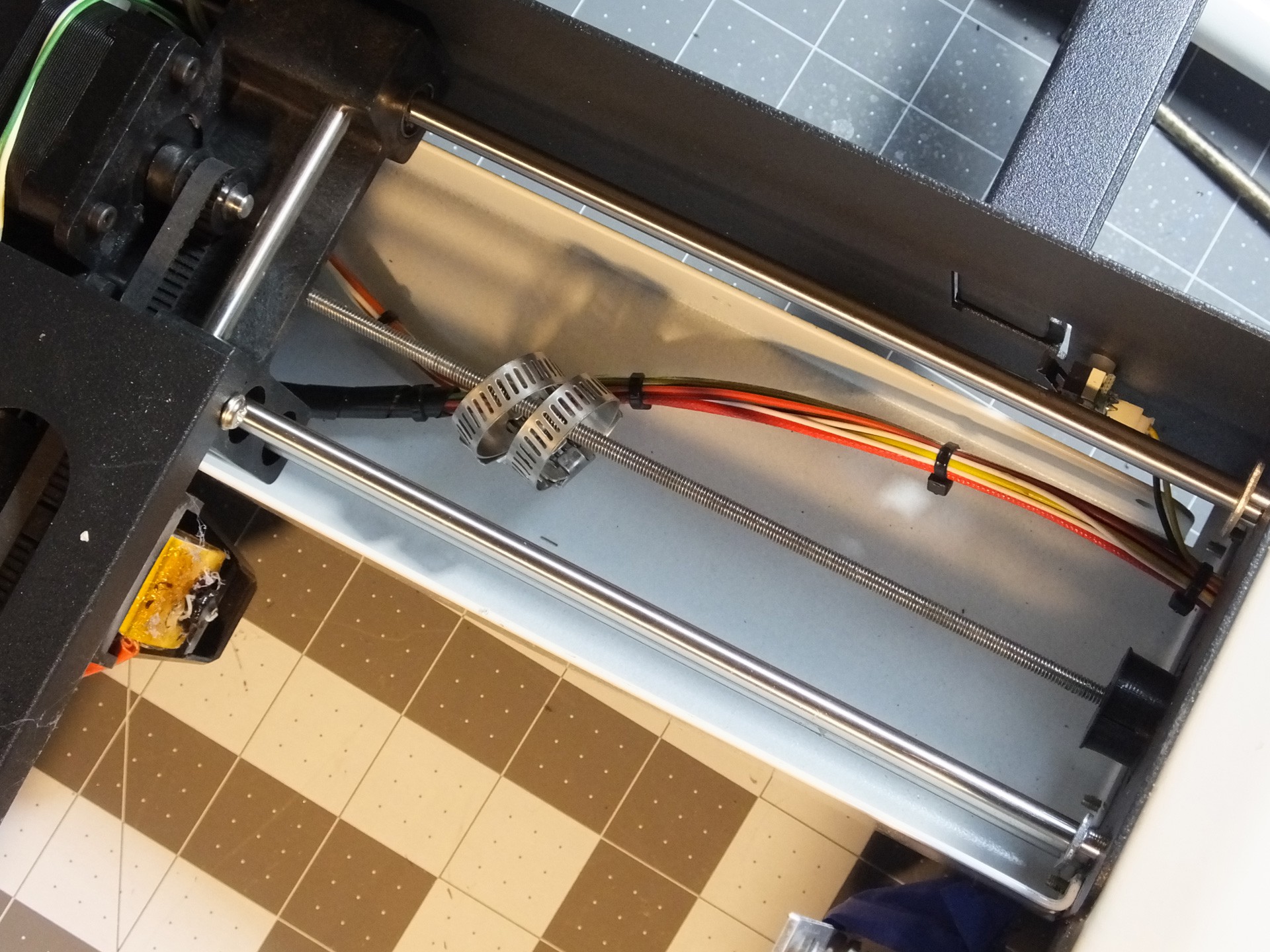 Now, insert the Threaded Rod through the hole and slide the Hose Clamps over the rod before you start threading it back into the Gantry where you removed it. Keep screwing the Threaded Rod into the Gantry until you can seat the Stepper Motor back where it belongs and screw it back in place, making note to get the connector back in the right position to reach the connector on the wiring harness.
 Now you can slide the Hose Clamps down into the grooves in the New Coupler and tighten them up, to secure the Threaded Rod and Z-Axis Motor Shaft in perfect alignment.
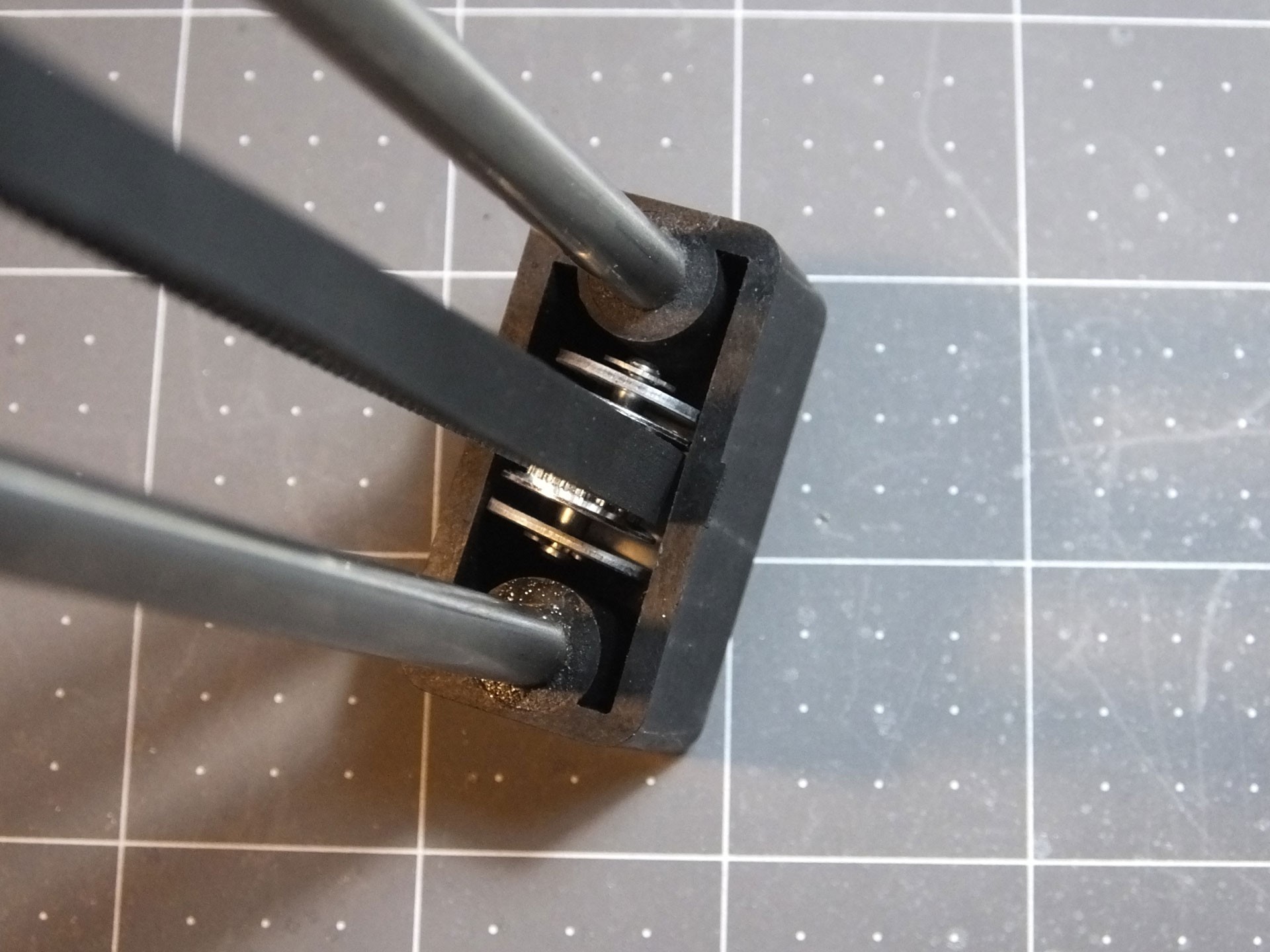 See how the pulley bracket is twisted? This is really annoying, and every time you install this pulley you have to mess around and try and get it straight by hand. Because this annoys me, I created an Alignment Clip that goes between the pulley bracket and the plastic channel where the pulley sits, which keeps the pulley at a perfect right angle to the rods, which will make the belt perfectly flat and level.
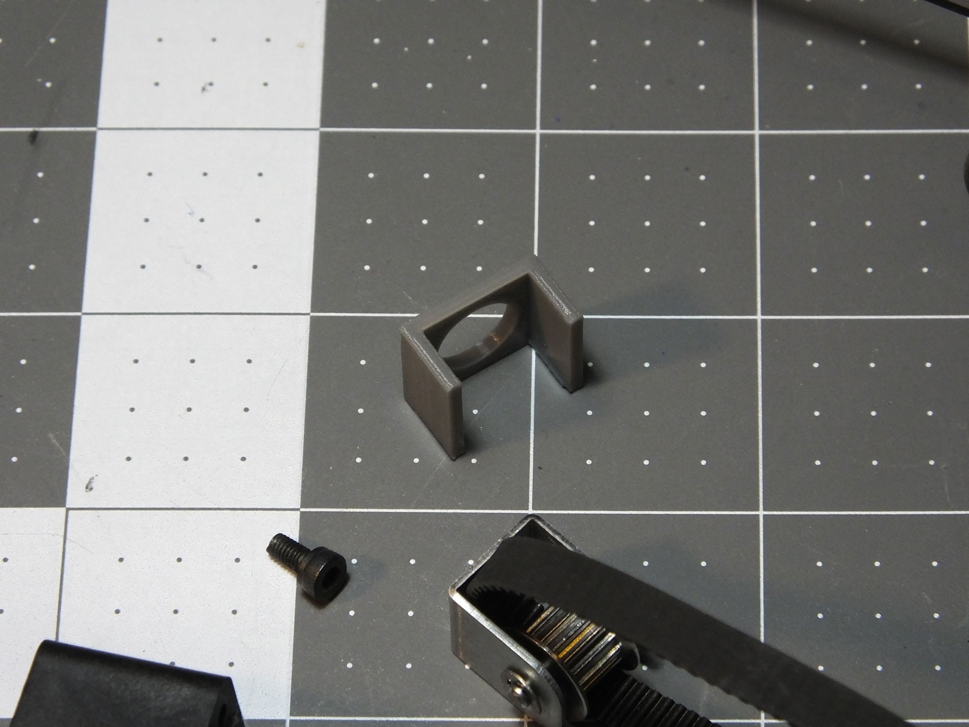 Here is what the Alignment Clip looks like before it is installed. To install the alignment bracket, you can clip it over the pulley bracket and insert it into the channel in the end of the gantry, or put the Alignment Clip in the channel first and then install the pulley bracket. If you want to print your very own Alignment Clip, you can get the model from my Thingiverse Page:
 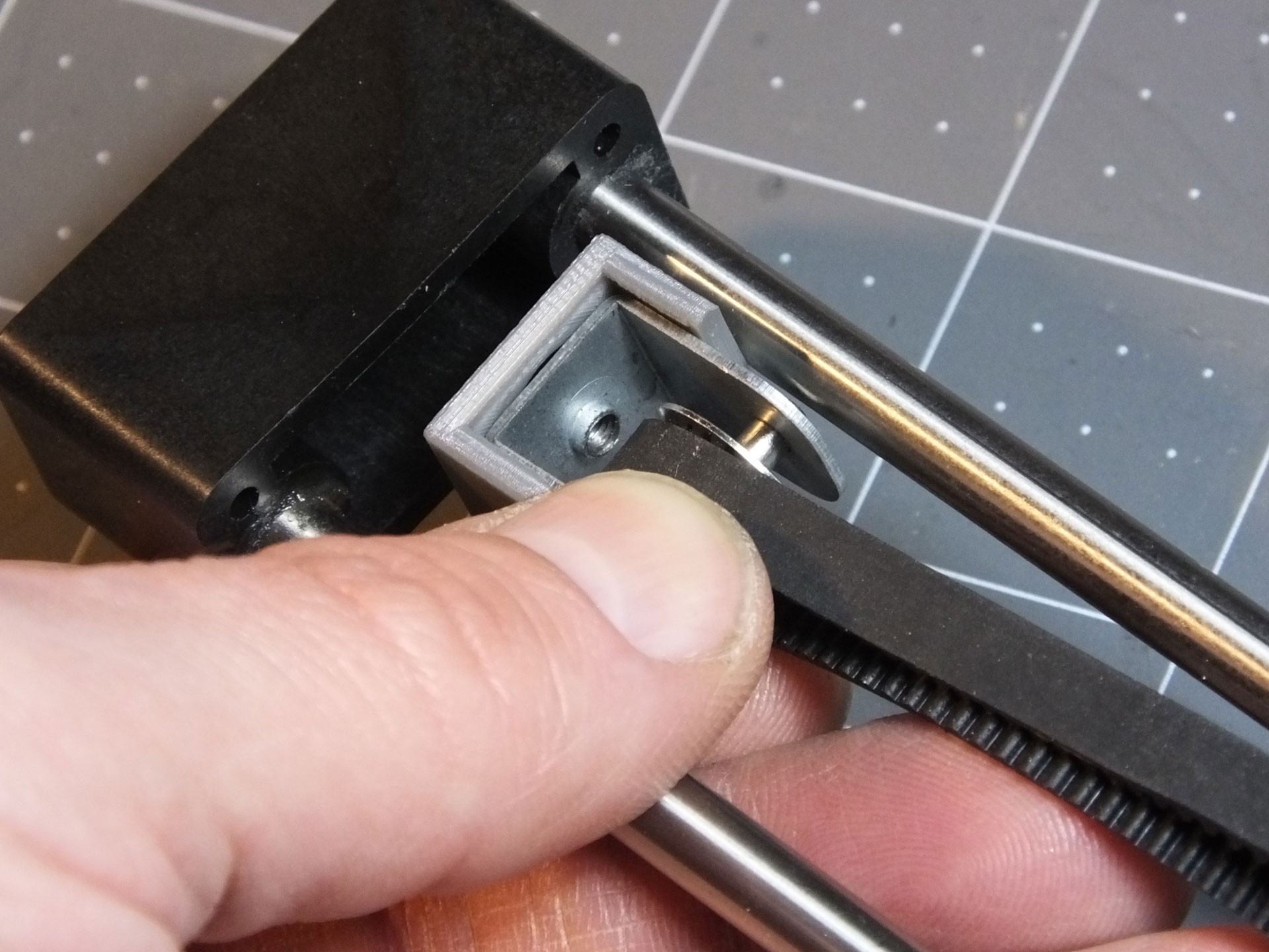 Note the orientation of the Alignment clip. It should only clip on one way and should center itself once you install it on the gantry. It should fit snugly in the channel, and prevent the pulley from twisting.
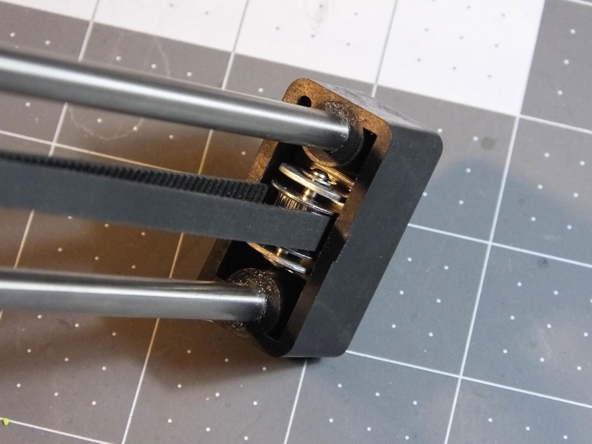 Here's the "After" photo, showing how nice and straight the pulley is now that it can't twist. Does this affect print quality or the life of the belt and pulley? I'm not sure. However, it takes only a couple of minutes to print, and makes working on the belt and pulley totally effortless. You don't have to fuss with the alignment of the pulley by hand any longer.