 U.S. Water Rockets
Since we got the printer for $32 less than list price, our unwritten goal is to try and spend less then $32 on upgrades, and see what quality we can get. Consider that this printer has a small build area (which we will maximize in the project) we will not be printing huge projects with this printer. But that's okay, because it makes sense that a small printer should print small items and print them with exceptional detail, so our objective is to be able to print highly detailed models, and articulated models or functional mechanical designs, so detailed print quality will be our benchmark for the print quality we are shooting for. On a printer this small, we're not really trying to go for warp speed printing as the goal, so our upgrades will be focused on detail, over speed. It is very likely that anything we do for improved detail will also help at higher speeds.
0%
0%
Monoprice Select Mini Maximum 3D Printer Mods
Low/zero cost upgrades for the Monoprice Select Mini 3D Printer.
Become a Hackaday.io member
Already have an account? Log in.
Just one more thing
To make the experience fit your profile, pick a username and tell us what interests you.
Pick an awesome username
hackaday.io/
Your profile's URL: hackaday.io/username. Max 25 alphanumeric characters.
Pick a few interests
Projects that share your interests
People that share your interests
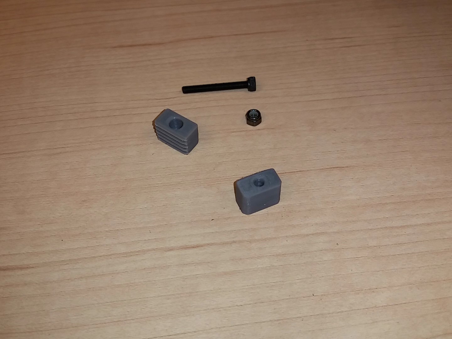 You will also need some fasteners for this project. You will need one 25mm M3 socket cap screw, two 16mm M3 socket cap screws, and three M3 Nylock nuts. You can use standard nuts, but we strongly recommend the use of Nylock nuts because they will not vibrate loose.
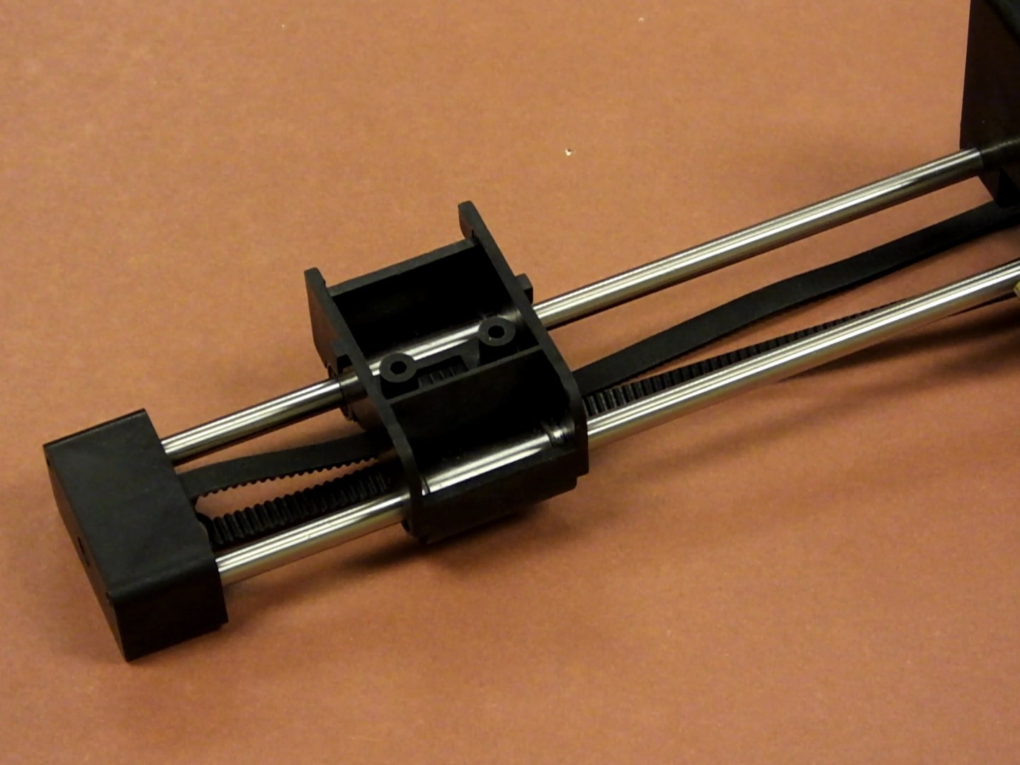
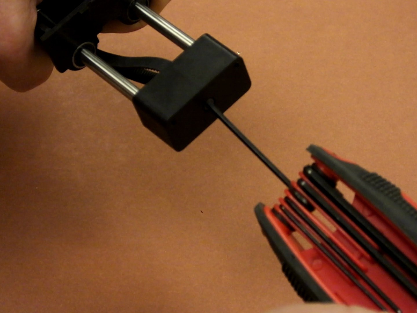
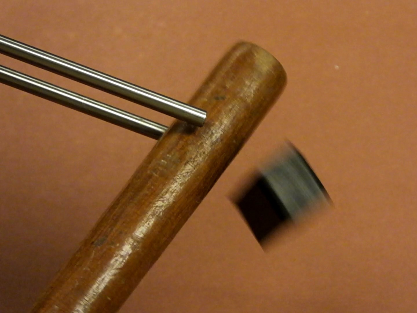 Gently tap on the inside of the plastic end cap for the X-Axis linear rods, until it pops off. It is just pressure fit on, and should come off relatively easily with a few sharp raps on the back side.
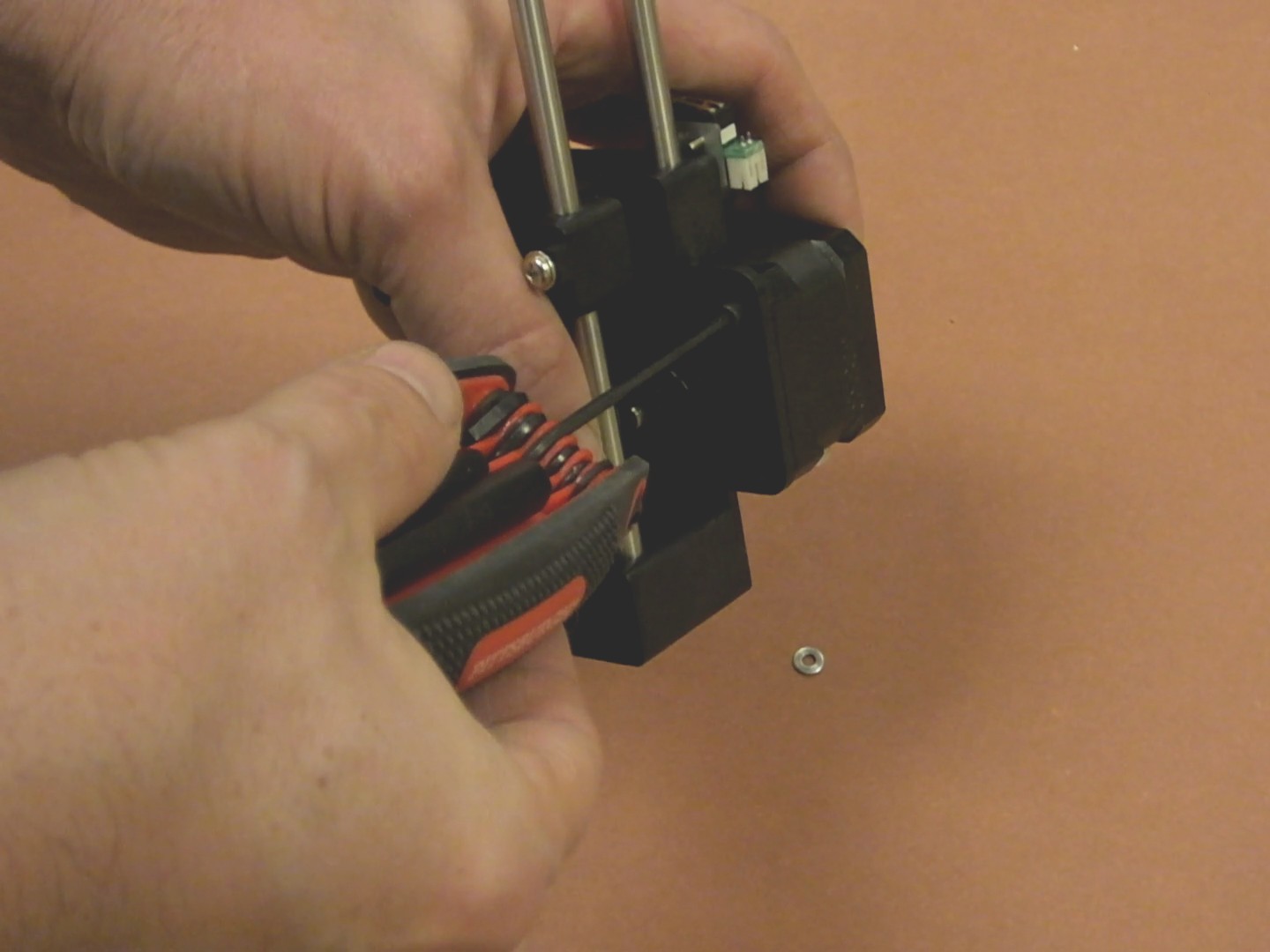
 P
P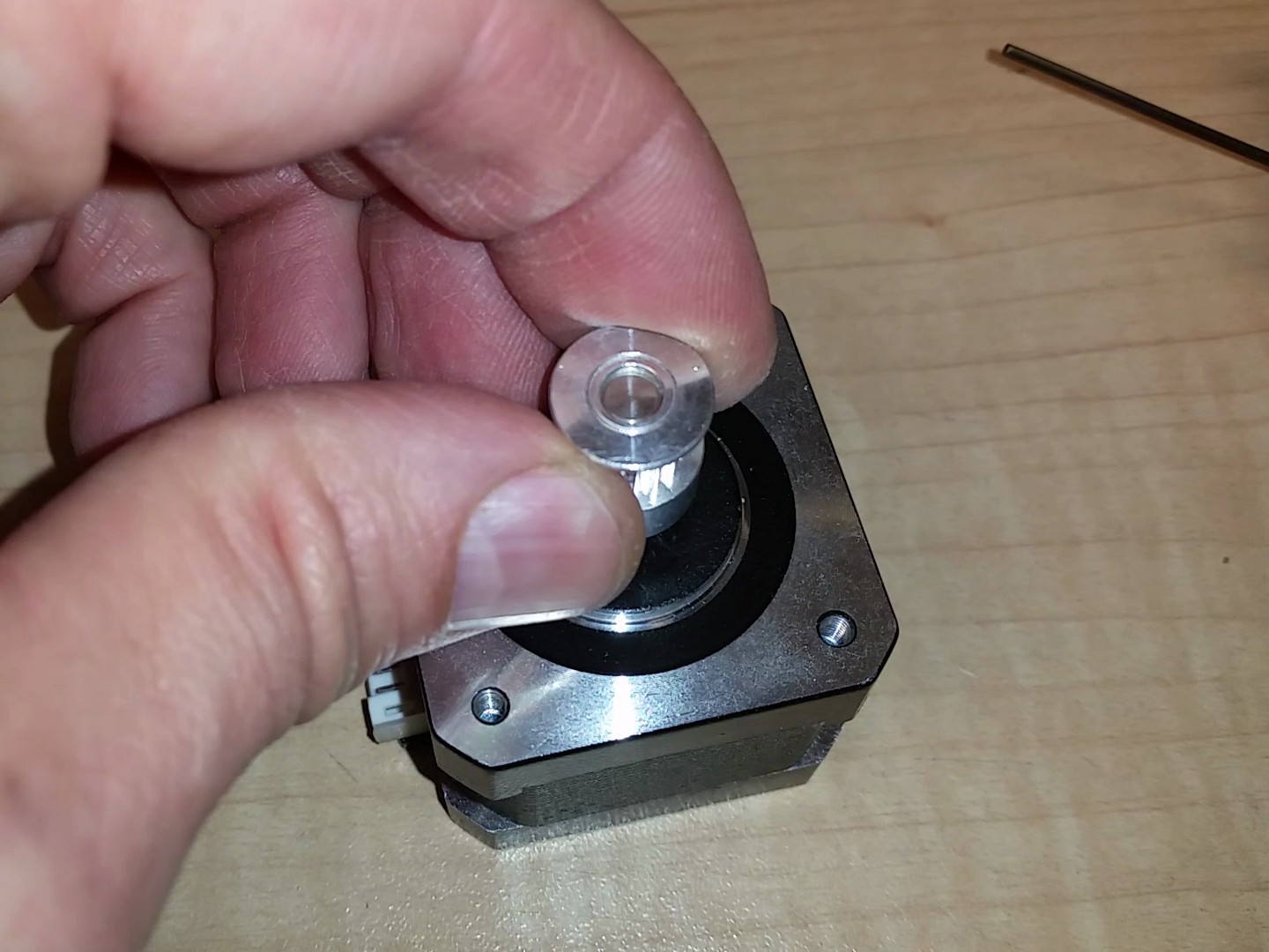
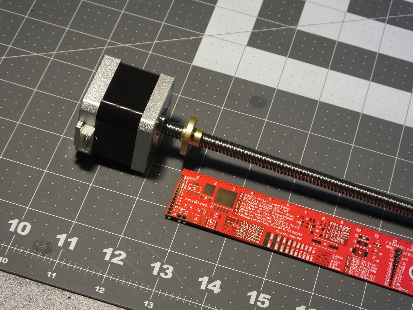 The first thing you need is a NEMA17 motor with leadscrew with a matching nut. I was able to find several sets of them on
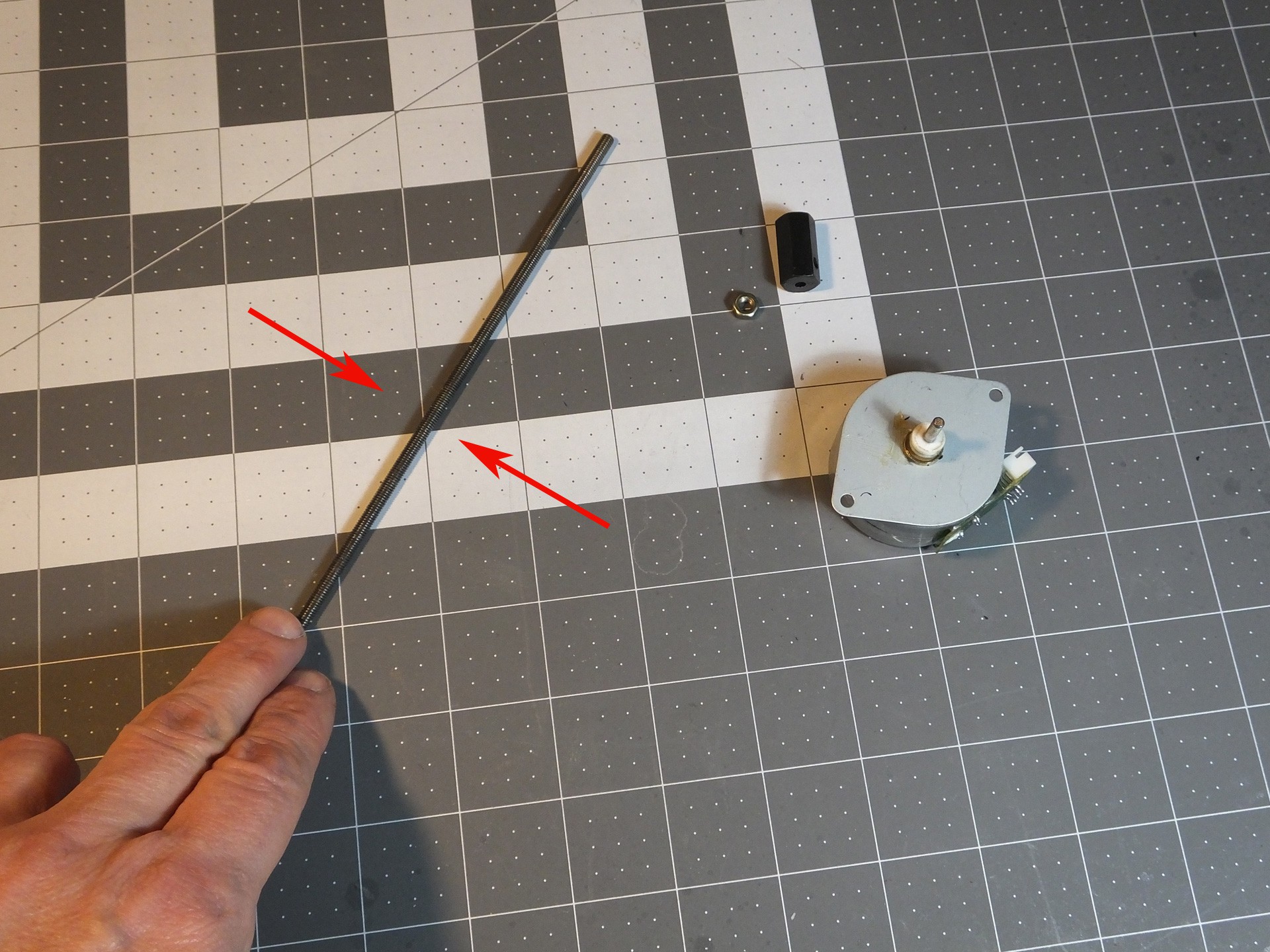
 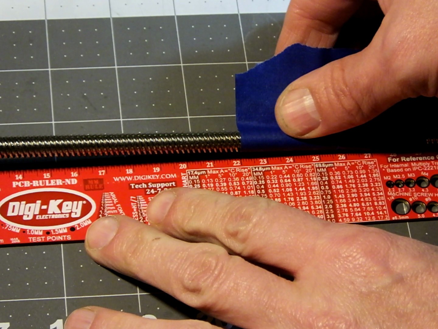 Through some careful measurement and calibrated guesswork, I determined that the lead screw for the Mini with this modification should be 220mm in length, so I measured the correct distance from the top of the NEMA17 Motor, and marked the spot to cut with a piece of tape I happened to have laying around.
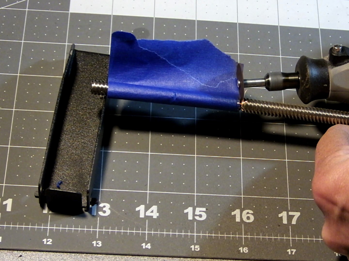 I used a rotary tool with a cutting wheel installed to cut the leadscrew to the proper length. I tried to do this as carefully as possible and as straight as possible, by rotating the leadscrew by hand as I cut into it around the perimeter and toward the middle until the excess part fell off.
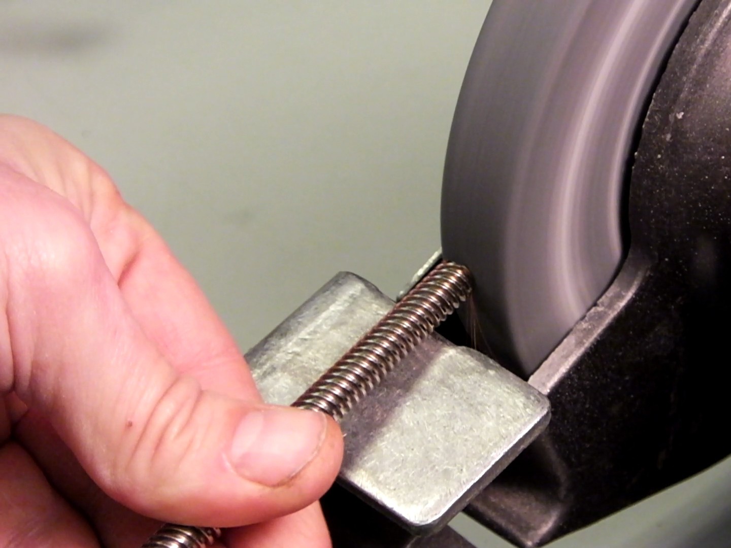 The cut end of the lead screw was a little jagged and had sharp edges and it was difficult to get the nut to thread on, so I used a bench grinder to round off the end of the lead screw to get rid of the sharp edges. Now the not would go on and off easily. With the motor prepared, it's time to dig into the guts of the mini and swap the motors and lead screws. I've already detailed how to remove the existing lead screw in my previous project entry:
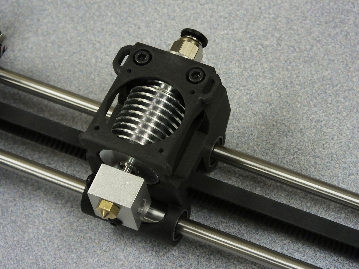
 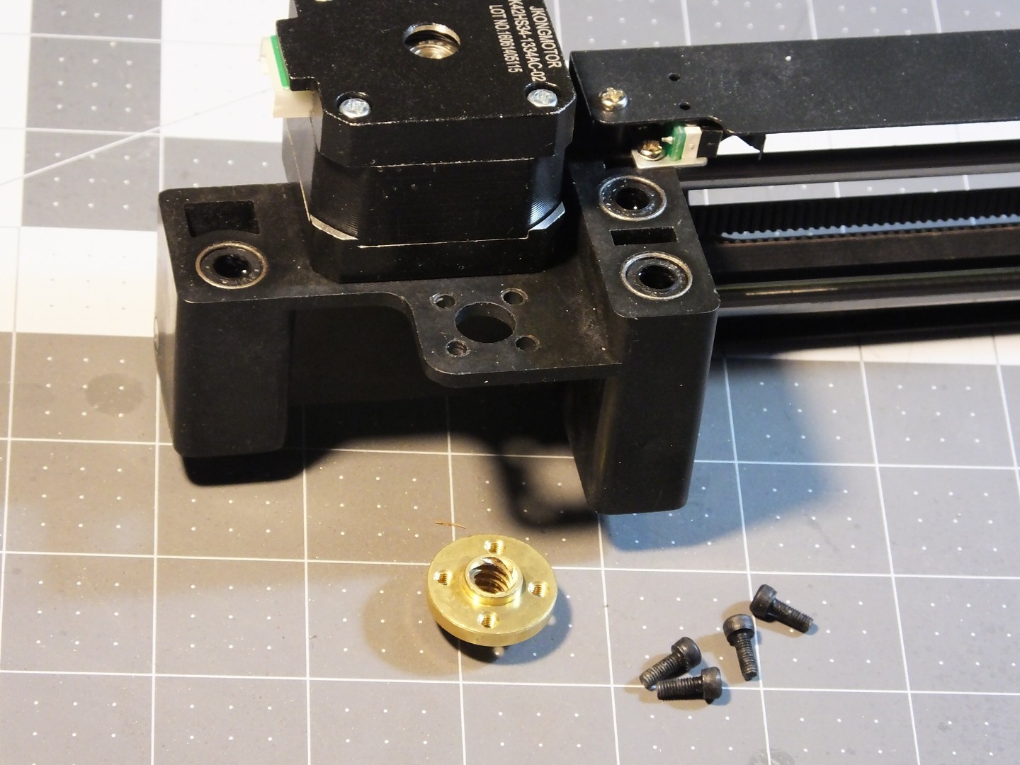 The next step is replacing the lead screw nut on the X-axis gantry with the new one that came with the leadscrew. Take out the 4 screws from the existing nut and swap in the new nut. You will need some M3 screws to hold the new nut in place. Note that the nut can sit on top of or below the gantry. If you use a separate motor and leadscrew with a coupler, you will possibly have to put the leadscrew nut on the top of the gantry to leave space for the coupler under the gantry.
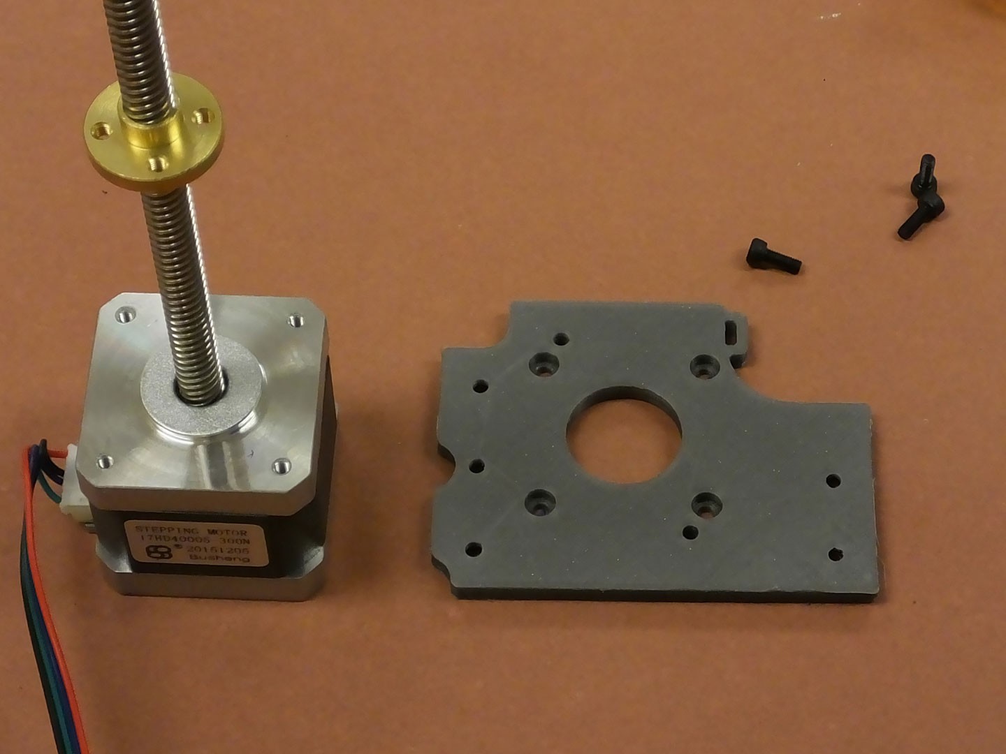 You should have a printed NEMA17 mounting bracket for the Z-axis already printed and ready to install. If not, grab the file from our Thingiverse page here:
 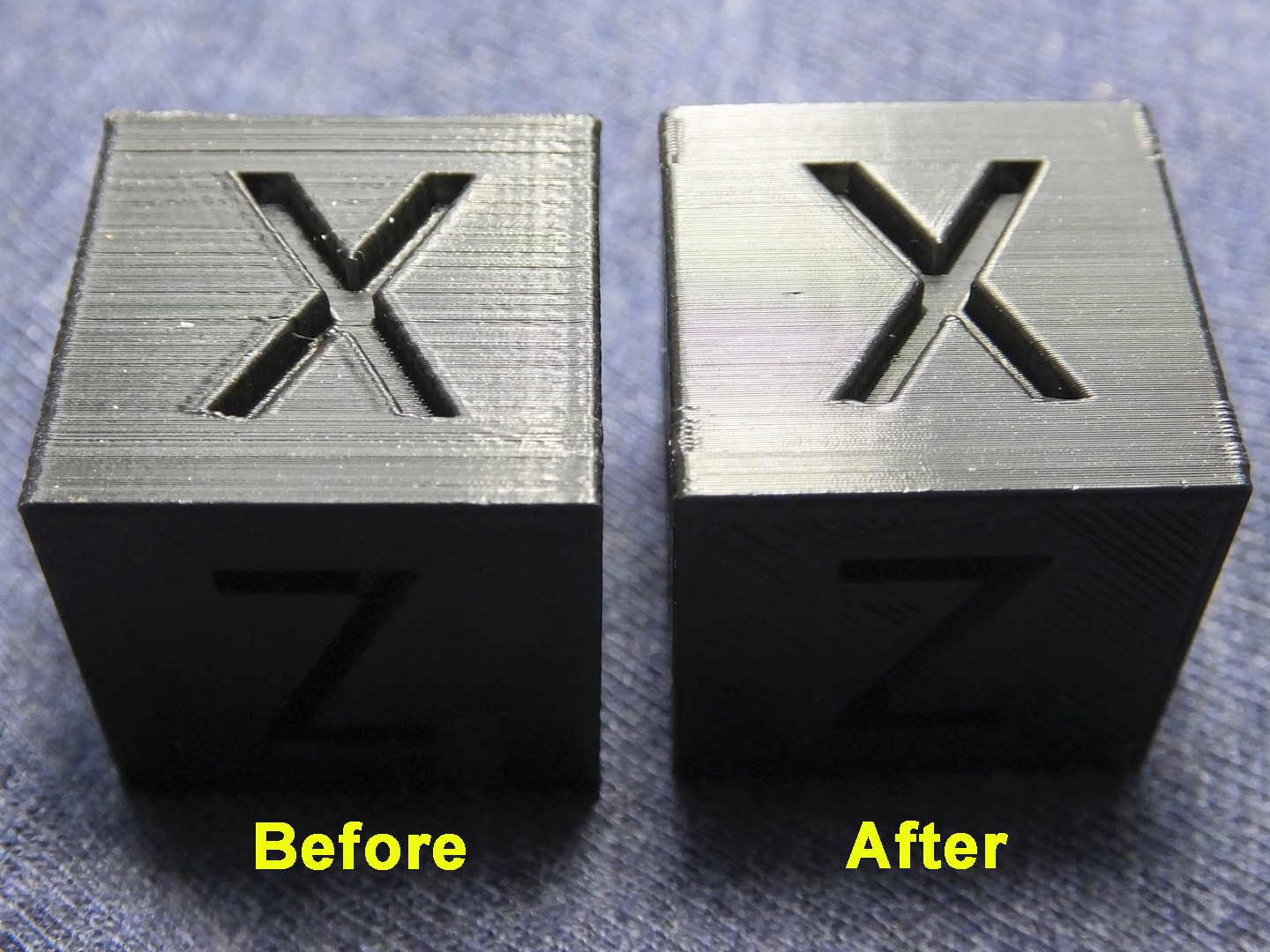 This was done on the same printer with the same filament at the same cura settings (except for a tiny difference in layer height due to different Z-axis thread pitch). You can see what a difference it makes!
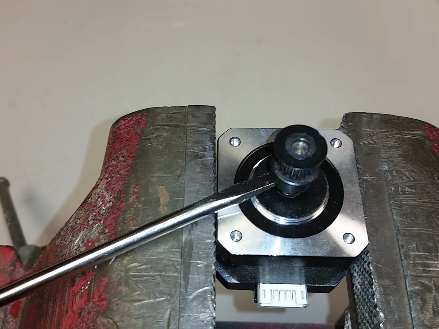
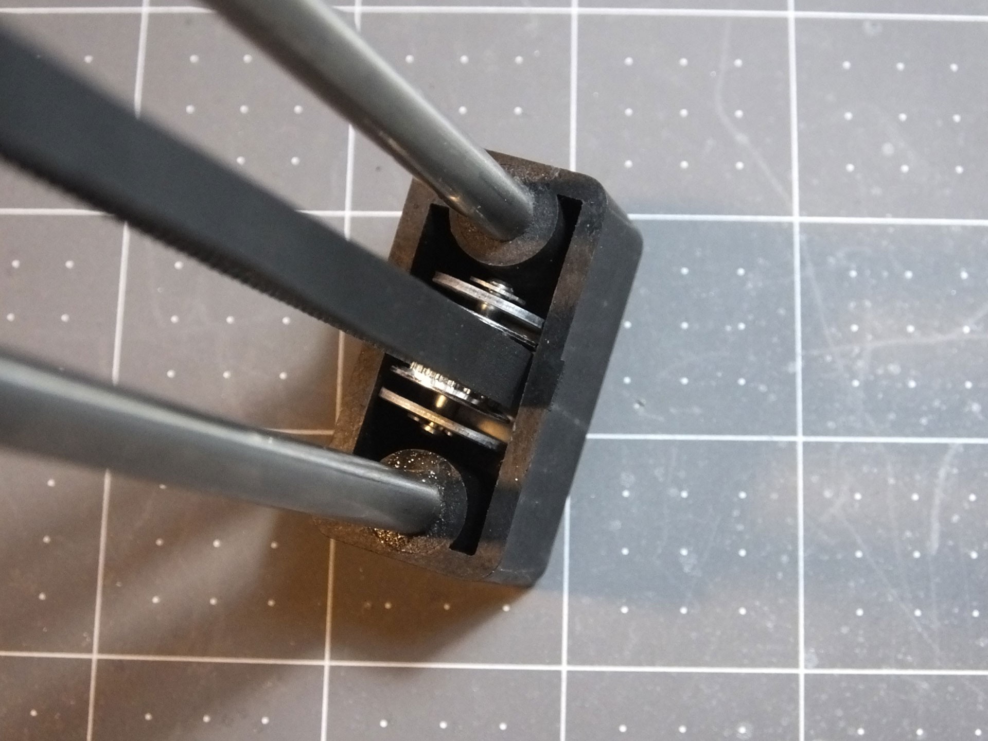 See how the pulley bracket is twisted? This is really annoying, and every time you install this pulley you have to mess around and try and get it straight by hand. Because this annoys me, I created an Alignment Clip that goes between the pulley bracket and the plastic channel where the pulley sits, which keeps the pulley at a perfect right angle to the rods, which will make the belt perfectly flat and level.
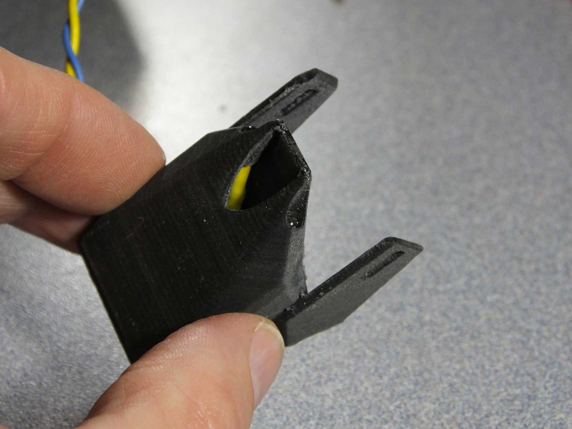
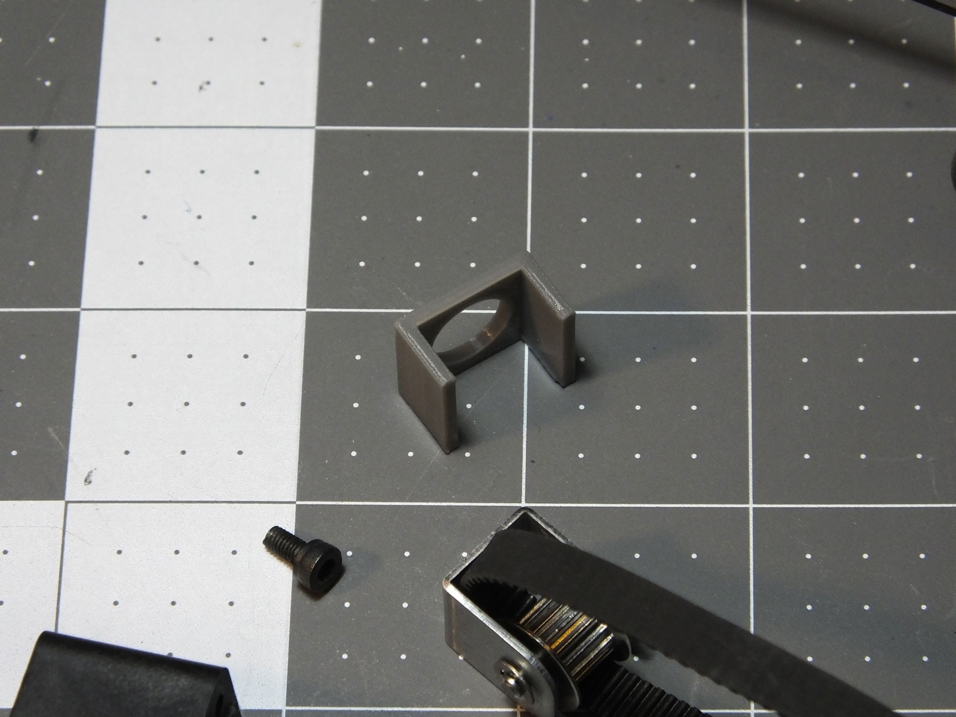 Here is what the Alignment Clip looks like before it is installed. To install the alignment bracket, you can clip it over the pulley bracket and insert it into the channel in the end of the gantry, or put the Alignment Clip in the channel first and then install the pulley bracket. If you want to print your very own Alignment Clip, you can get the model from my Thingiverse Page:
 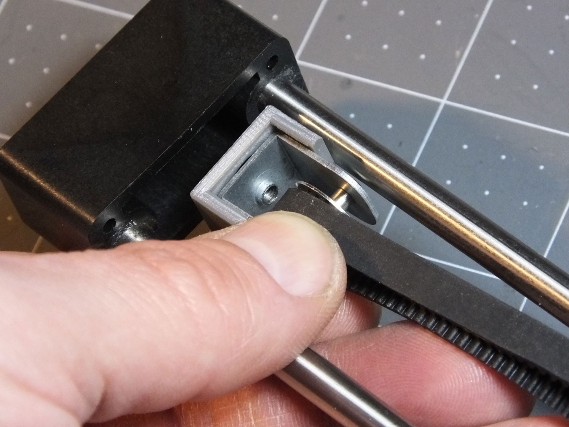 Note the orientation of the Alignment clip. It should only clip on one way and should center itself once you install it on the gantry. It should fit snugly in the channel, and prevent the pulley from twisting.
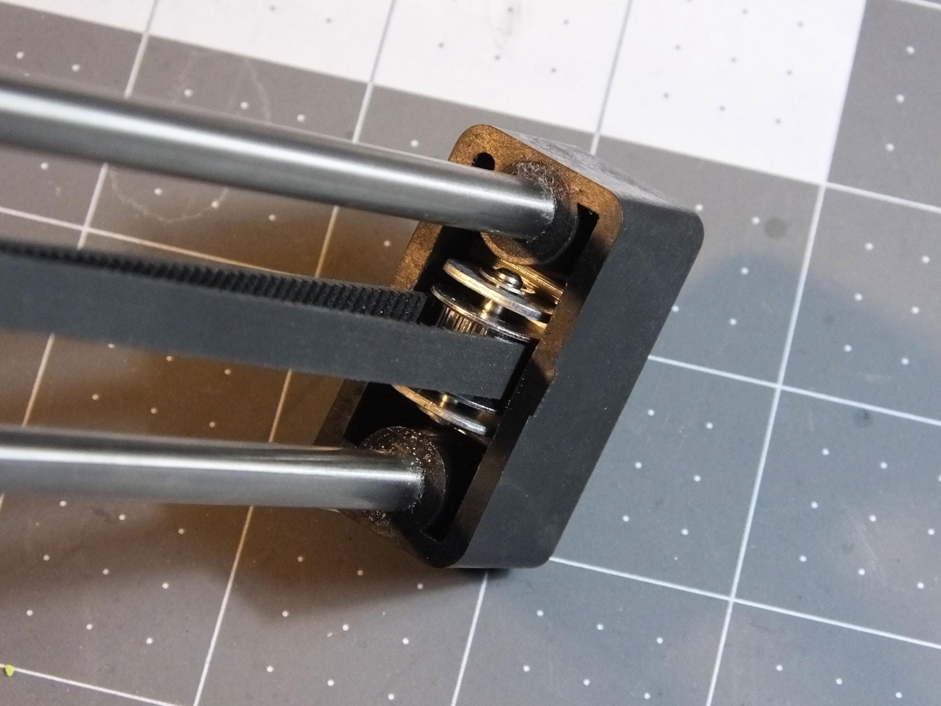 Here's the "After" photo, showing how nice and straight the pulley is now that it can't twist. Does this affect print quality or the life of the belt and pulley? I'm not sure. However, it takes only a couple of minutes to print, and makes working on the belt and pulley totally effortless. You don't have to fuss with the alignment of the pulley by hand any longer.
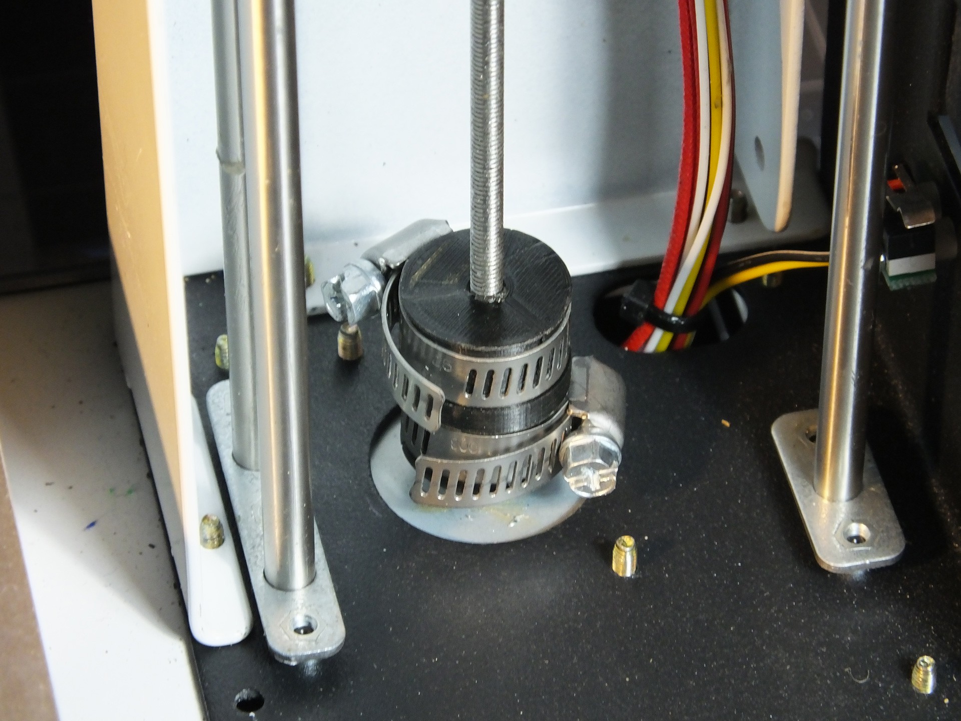 Several people in the Facebook Group for the Monoprice Select Mini have experienced severe issues with wobble in their Z-axis that is not cured by stabilizing the rails. I have seen several people who have observed that their print quality suffers because the stock coupler between the Z-Axis Stepper Motor and the Threaded Rod is not aligning the two shafts properly, or the grub screw is shifting the rod to one side. I decided to make a replacement for the coupler that forces the threaded rod into perfect alignment with the motor shaft. Get the file on my Thingiverse page:
 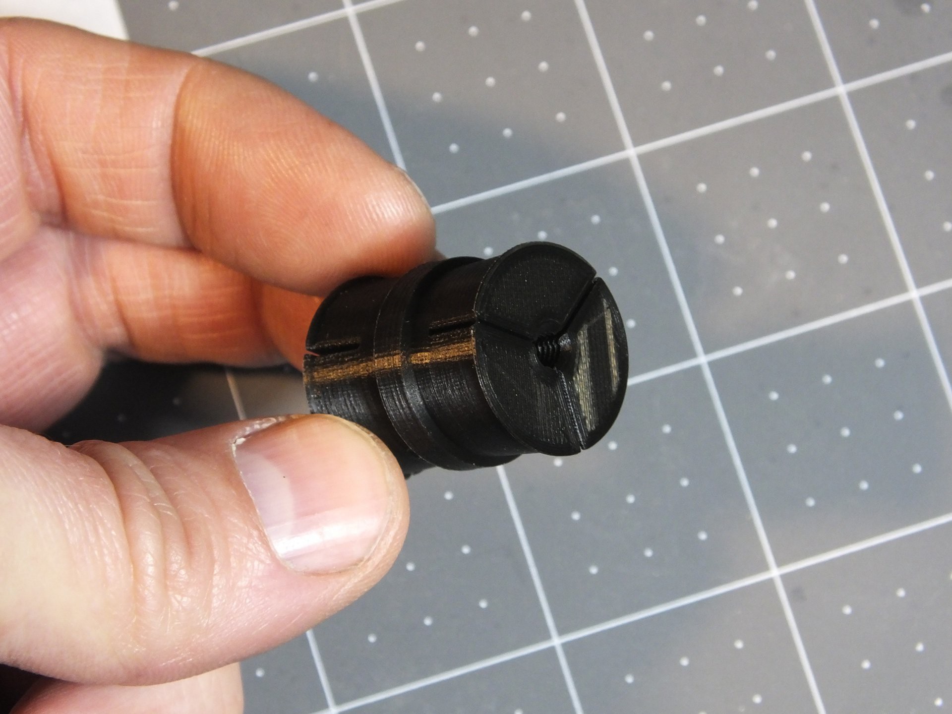 Here is the coupler which I designed. On one side it has threads for the 4mmx0.7 Threaded Rod, and the other side has a hole to accept the 3mm Motor Shaft. Three clamping surfaces per side will be used to hold the coupler firmly in place and force the two shafts into perfect alignment.
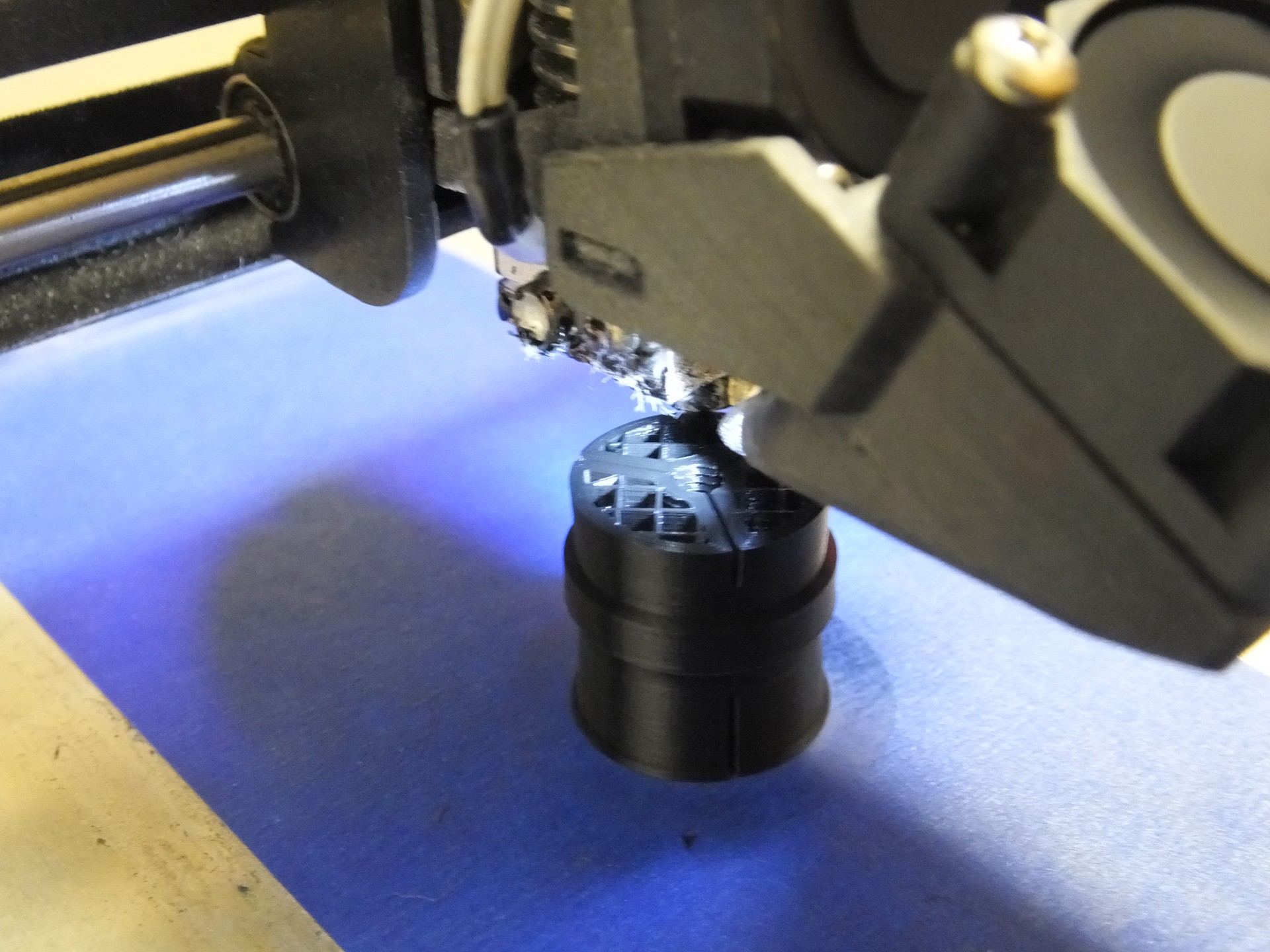 This piece will print perfectly fine with no supports and oriented so that the threaded hole is facing up. Please print with thick walls and a decent fill. I used 4 perimeters and 20% infill for this one. I do not think the plastic type is important because this part is not subjected to heat.
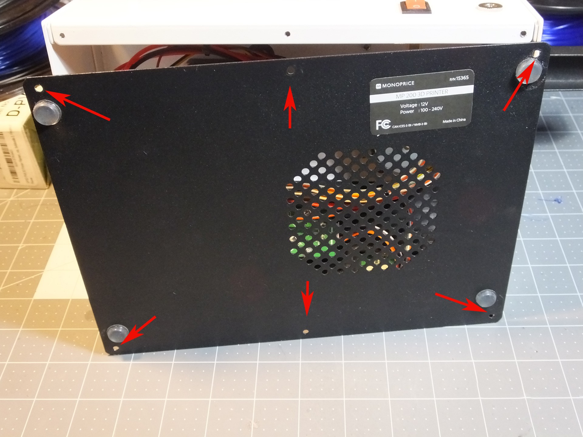 Installation is very simple: Begin by removing the six screws that hold the black metal bottom to the mini and pull the bottom off the printer.
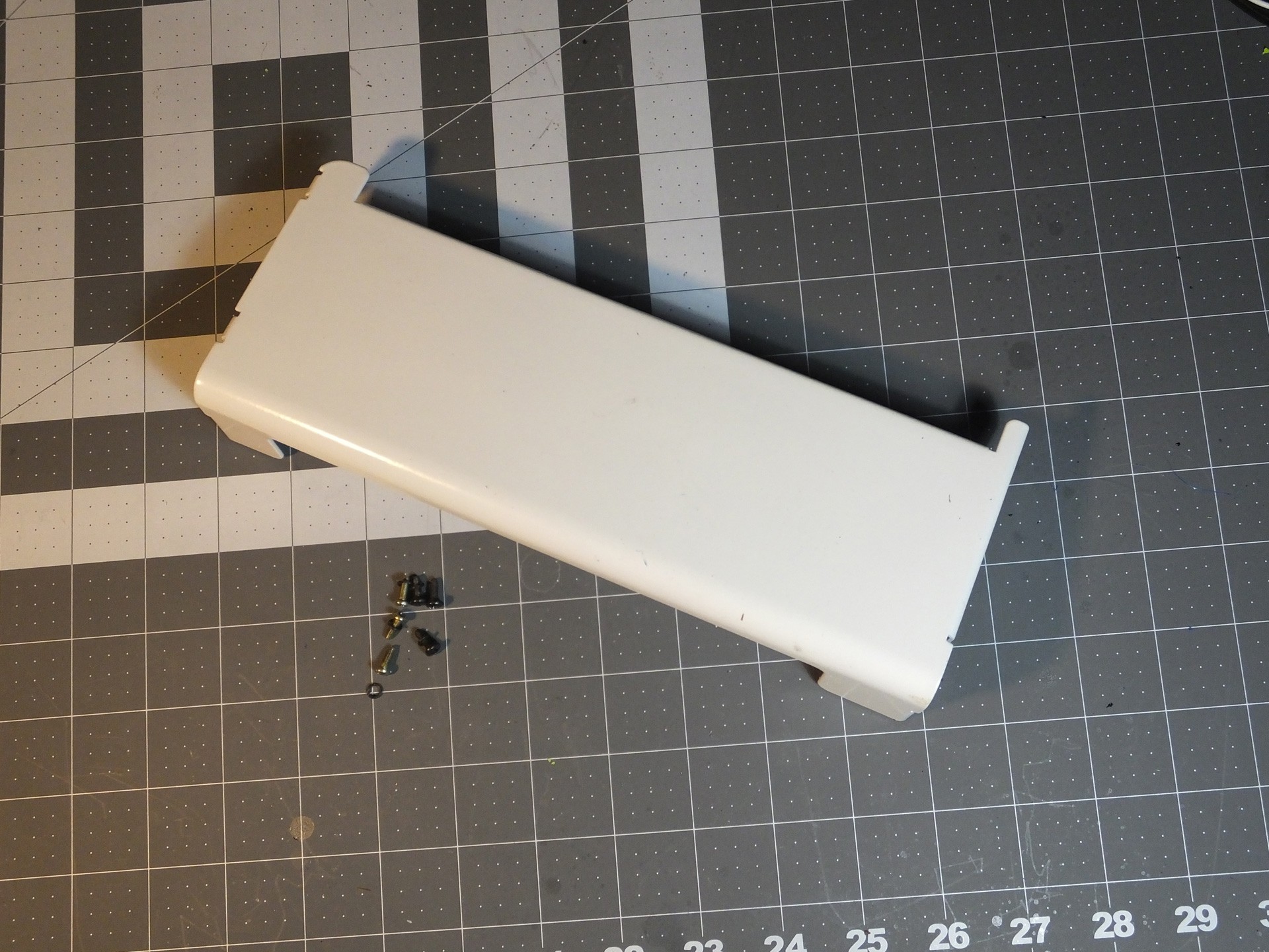
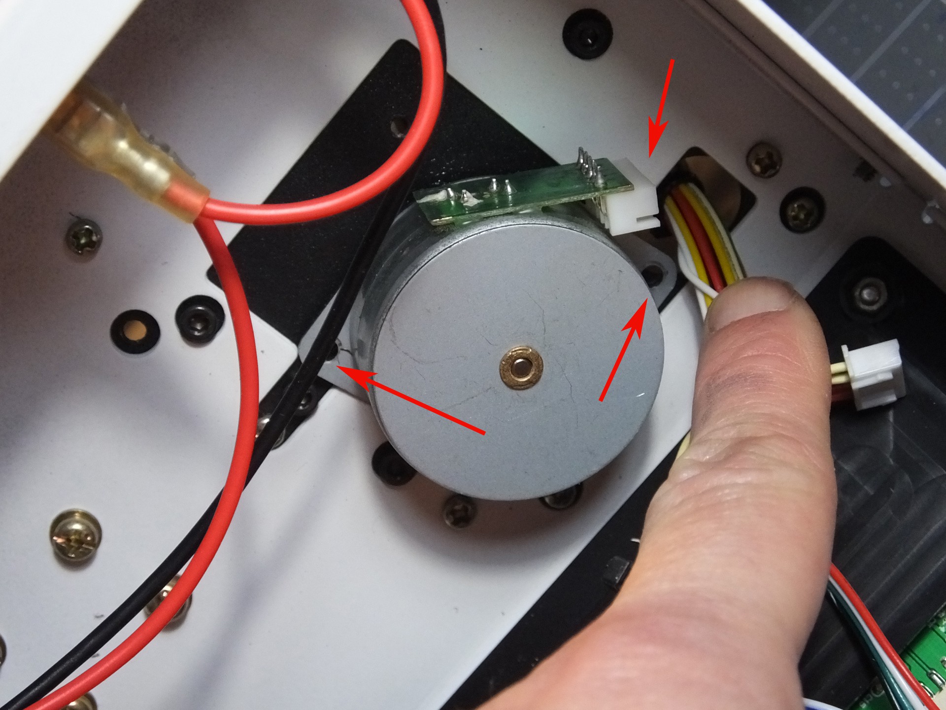 Remove the two screws holding the Z-Axis Stepper Motor to the underside of the tower. Also unplug the cable while you're in there. Note the position of the connector on the motor where the wires were plugged in. When you put the printer back together, you have a 50% chance of facing this in the wrong direction, unless you make a note this position now.
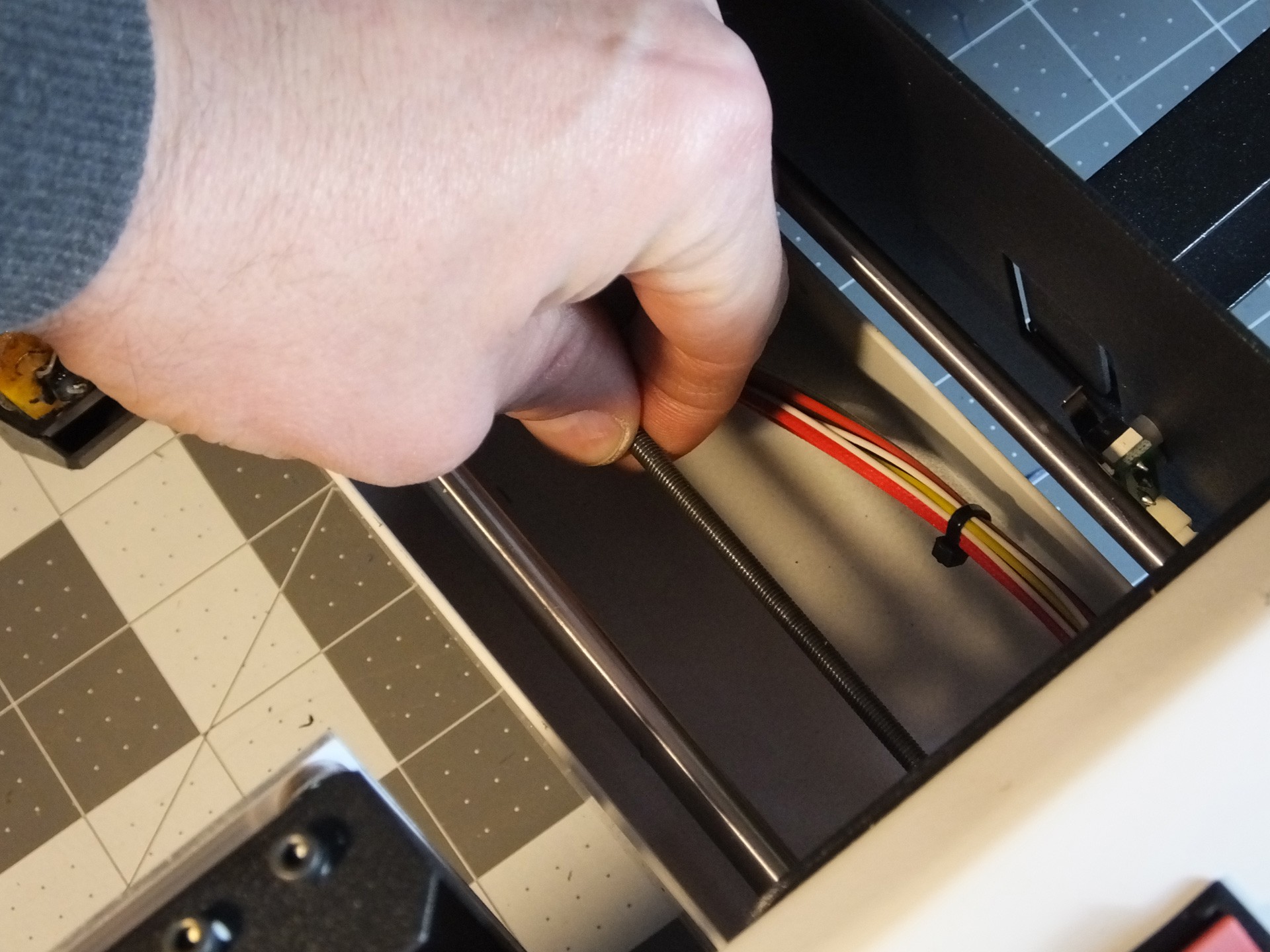 Spin the Threaded Rod to unscrew it from the Gantry. If you are reading these instructions before you began working then you get a bonus! When you begin work use the move menu to raise the Gantry all the way to the top before tearing down the printer. It will save you a lot of spinning of the Threaded Rod in this step here.
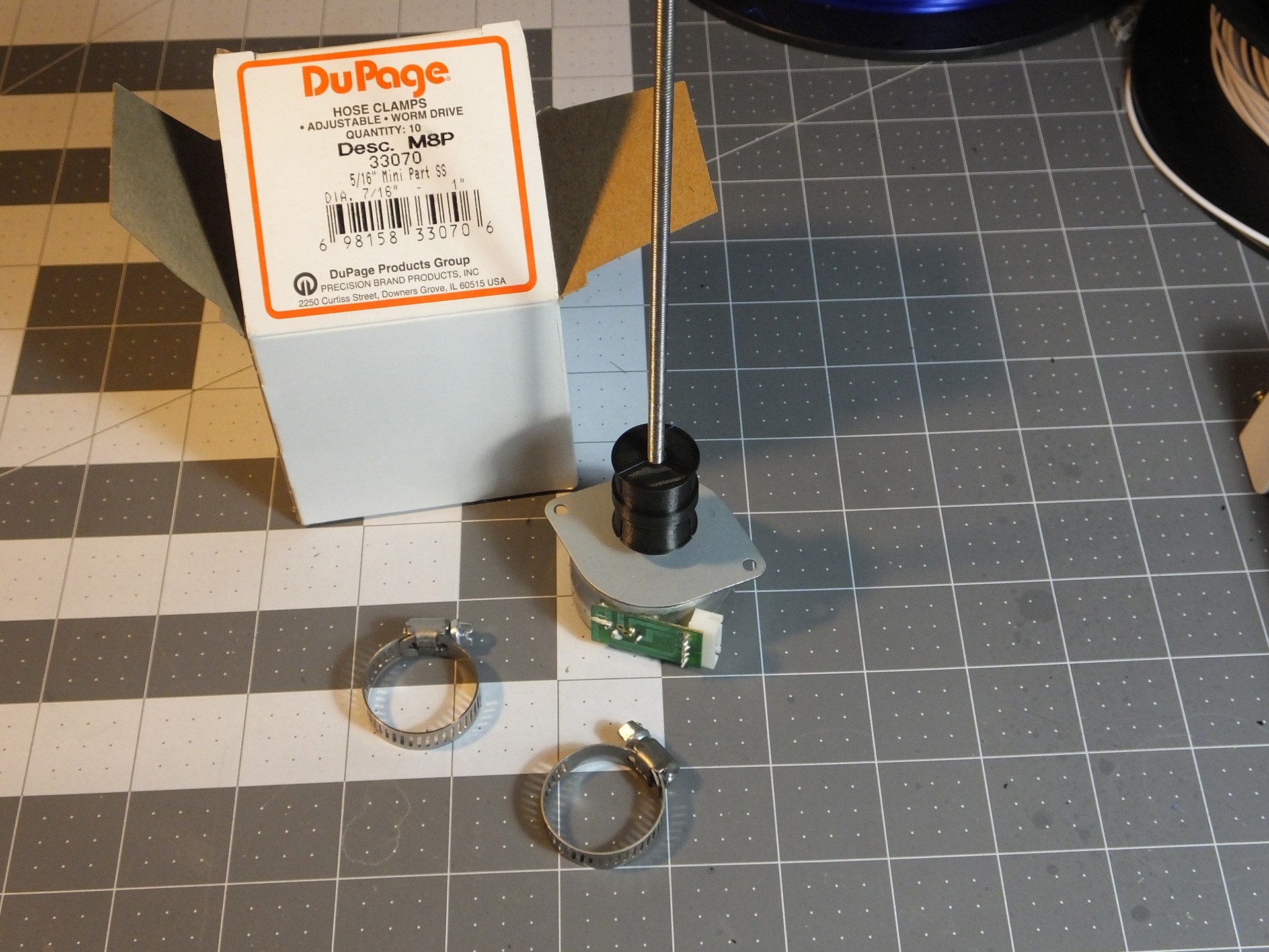 Push the unthreaded side of the New Coupler on the Motor Shaft until it just touches the spacers on the shaft. If you don't have spacers, don't go any closer to the motor than about 5mm. Then, thread the Threaded Rod into the threaded side of the New Coupler, and tighten it until it reaches the bottom of the hole. At this point you want to get a pair of Hose Clamps ready. The Hose Clamps should fit a 1" pipe and have a 5/16" wide band. Slightly smaller clamps should fit as well. Just prepare them by opening them up wide enough to fit over the New Coupler easily. DO NOT INSTALL THEM YET. If you do, you won't get the Stepper Motor back on.
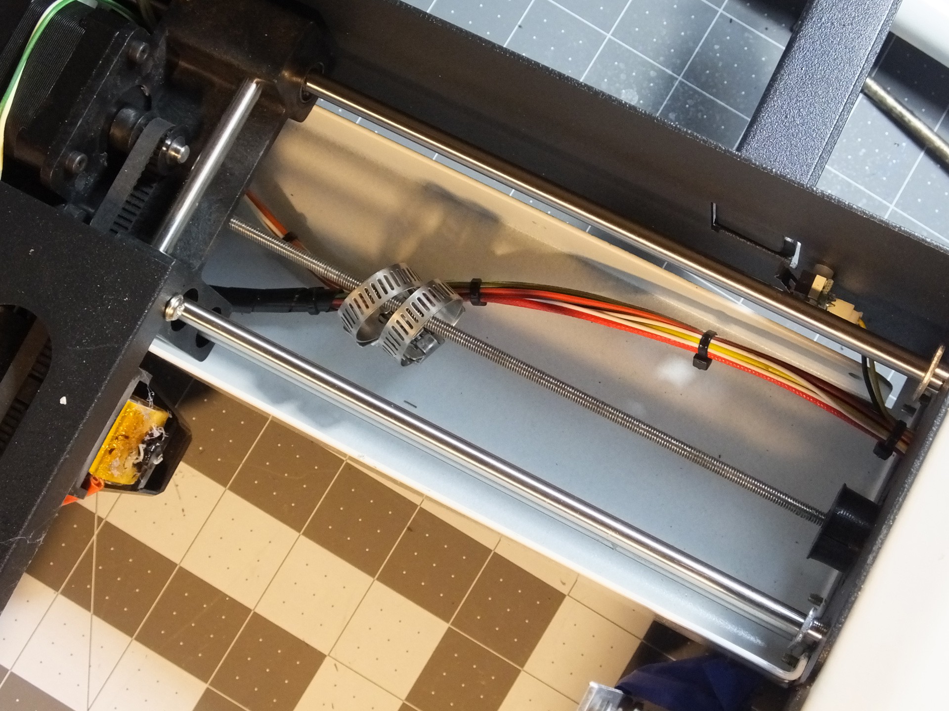 Now, insert the Threaded Rod through the hole and slide the Hose Clamps over the rod before you start threading it back into the Gantry where you removed it. Keep screwing the Threaded Rod into the Gantry until you can seat the Stepper Motor back where it belongs and screw it back in place, making note to get the connector back in the right position to reach the connector on...


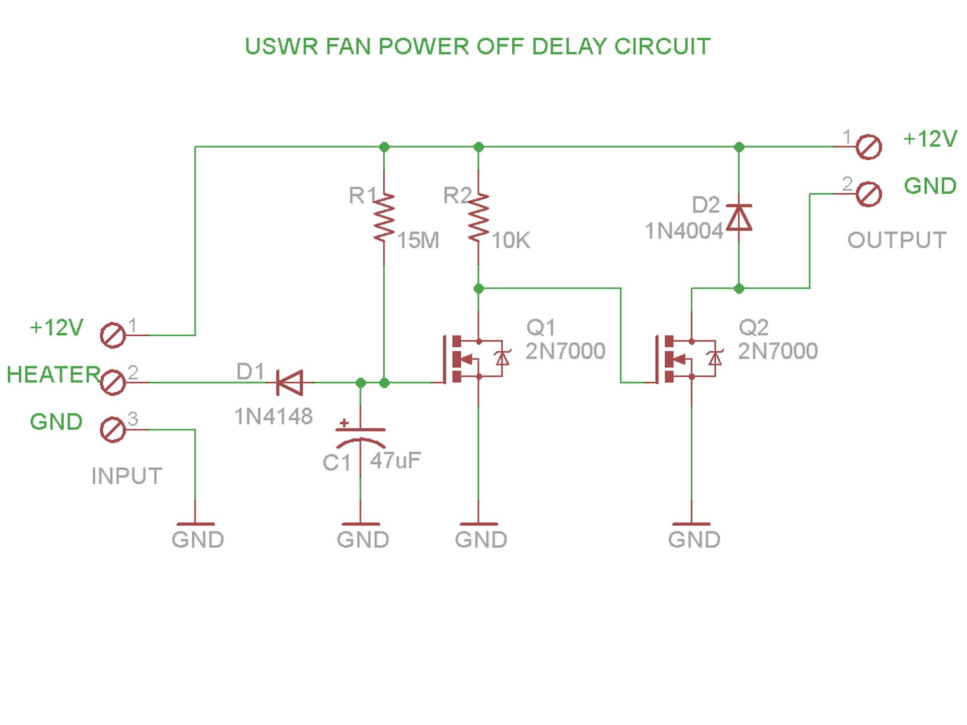 The operation of the circuit is quite simple: 12V is provided to the heater and the ground for the heater is connected by a FET on the control board, when the heater is turned on. We use this signal to monitor for the heater activity.
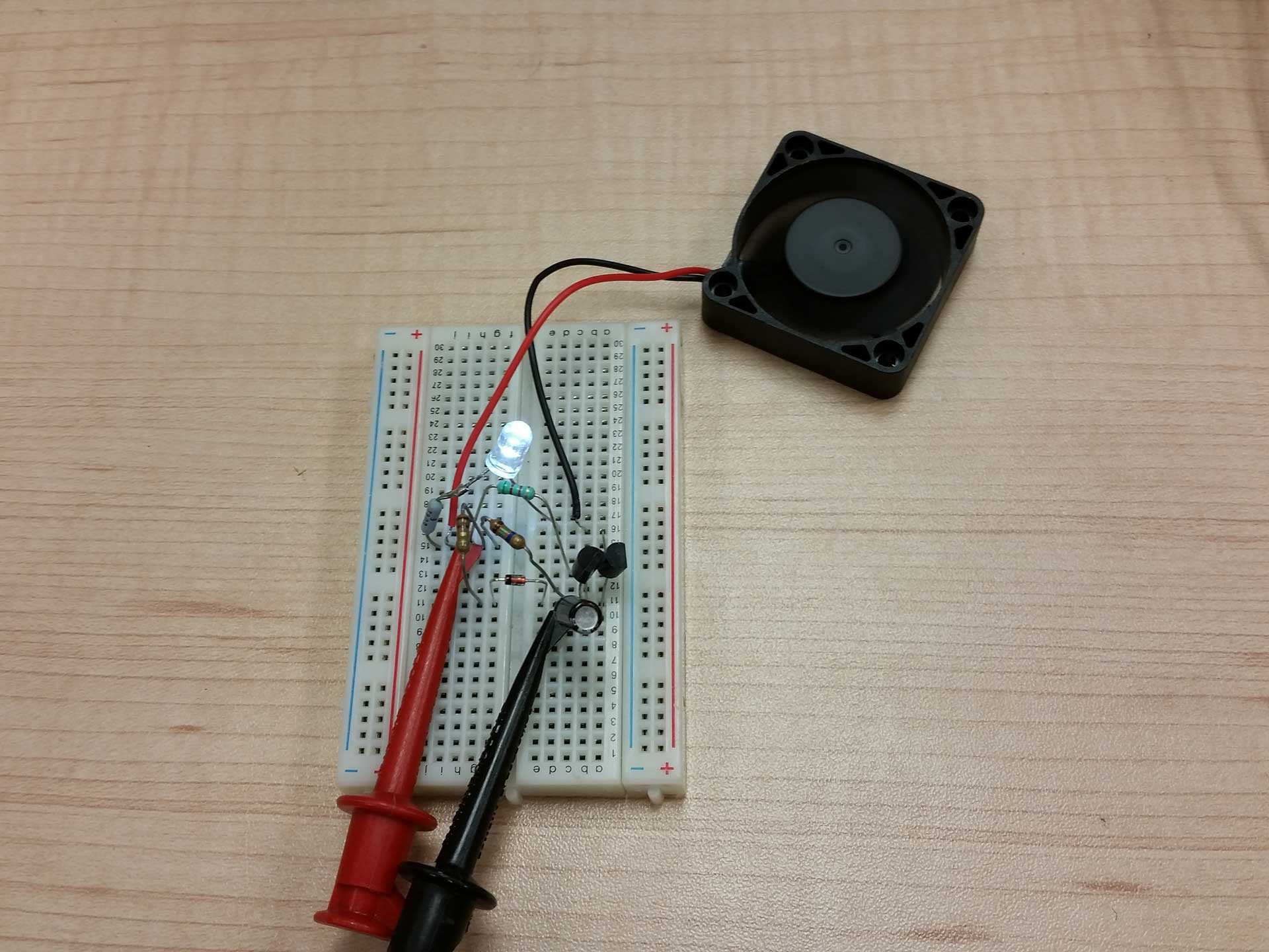 The circuit was mocked up and tested on a breadboard kit, using through-hole parts I had not touched in a few years. It was fun going back and doing this for a change.
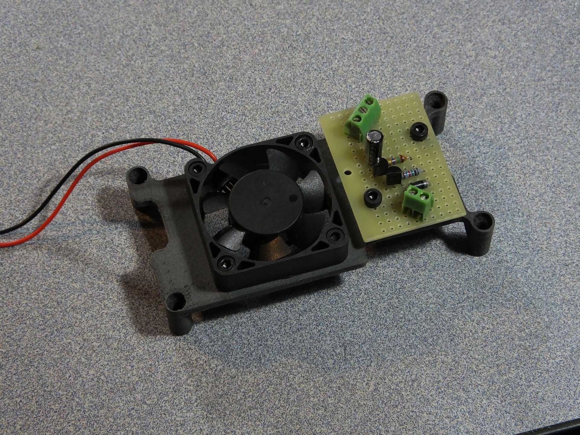
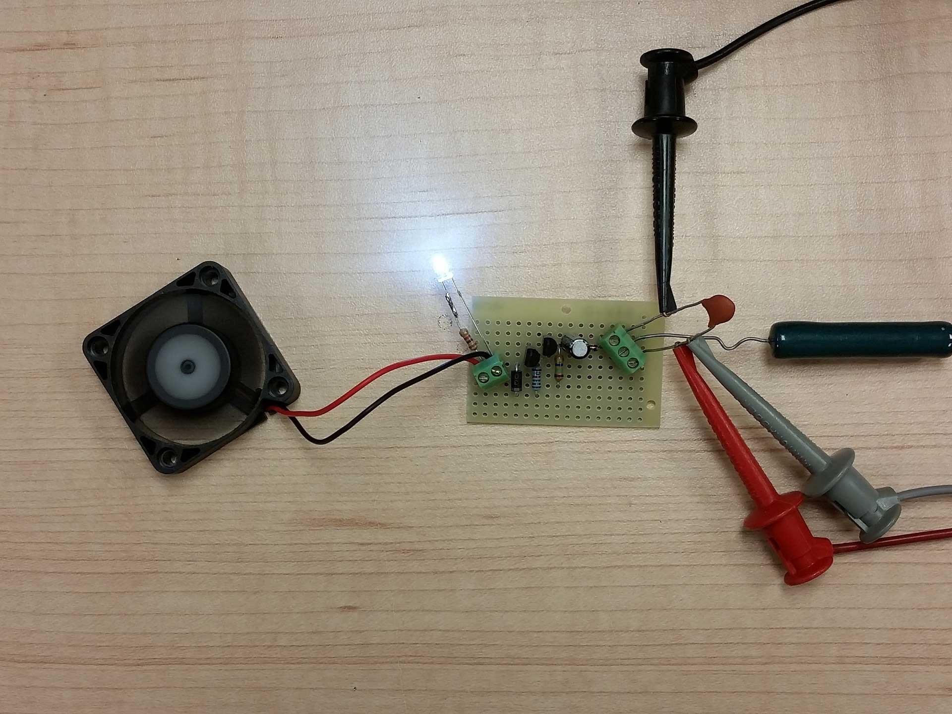 The circuit was then transplanted to some perf board for installation in my Select Mini. Above you can see where I used an old wire wound 10 ohm resistor to simulate the heater. Grounding the center terminal on the right simulates the pulsing of the heater ground on...
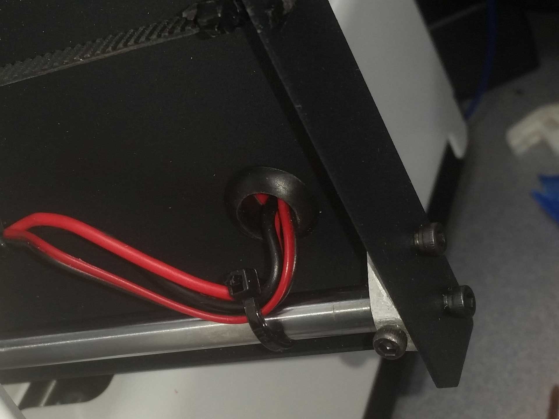 Check out the video below and see if you can spot the issue before I explain it and discuss my solution.
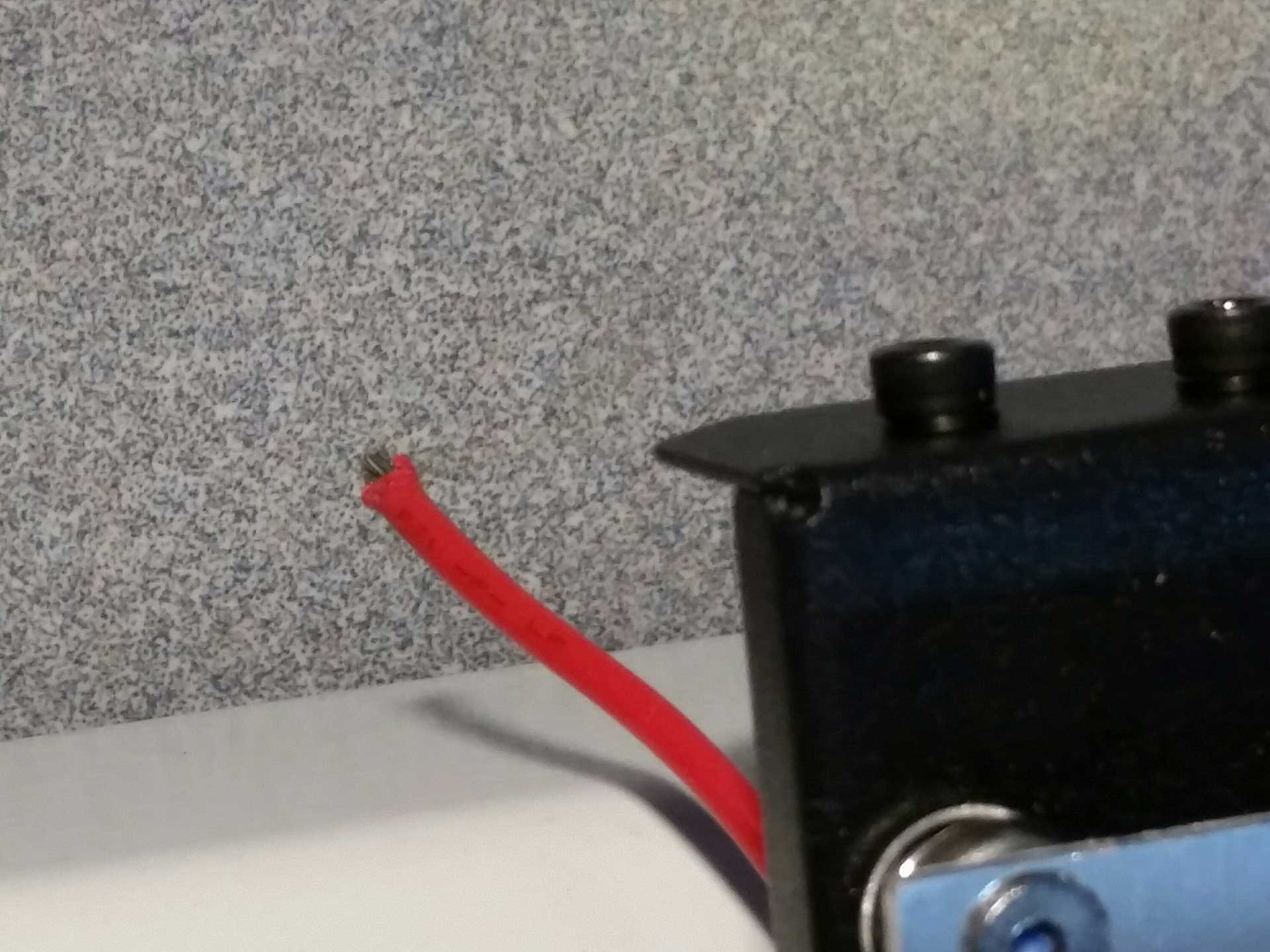
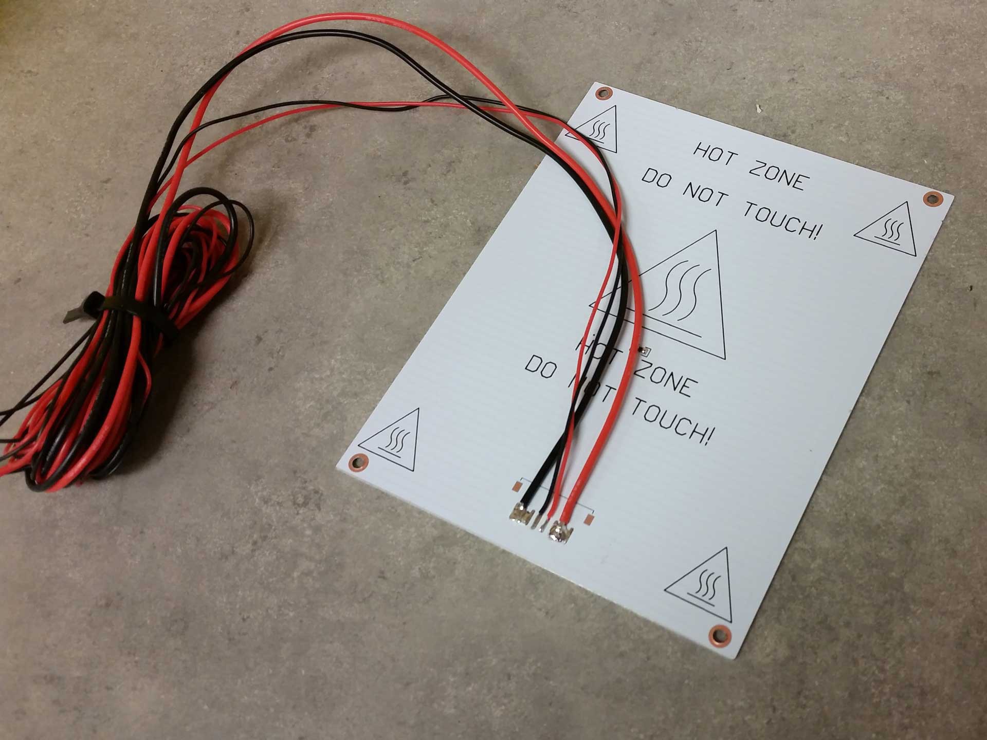 My solution was to replace the heated bed wiring with better quality wiring and route it so that there would be no stress on the wires and no interference with any of the moving parts. For the wiring, I chose to use silicone jacketed wire which I had on hand for my rocket and quadrotor experiments, which I purchased in bulk from Hobbyking. I probably only used a dollar or so of the wire if I were to buy it separately.
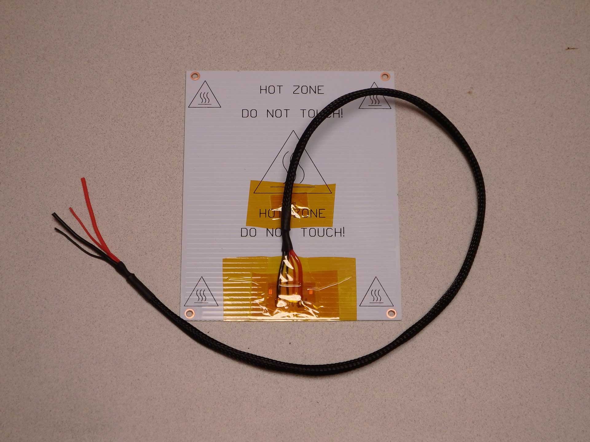
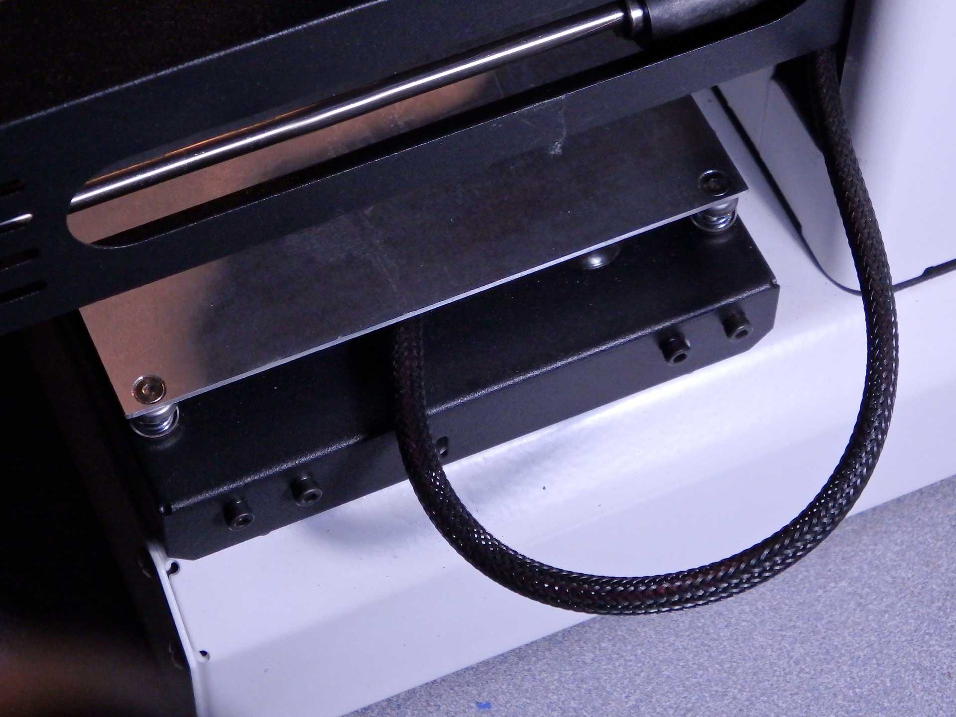 To solve the original Y-axis belt rubbing problem, I re-routed the heated bed wiring through the slot in the Z-axis tower. The gantry never lowered enough to interfere with the wiring, and the new cable routing solved all the issues with the belt. The wire actually moves very little ones it is not confined under the bed. This wire configuration should be standard on the Mini.
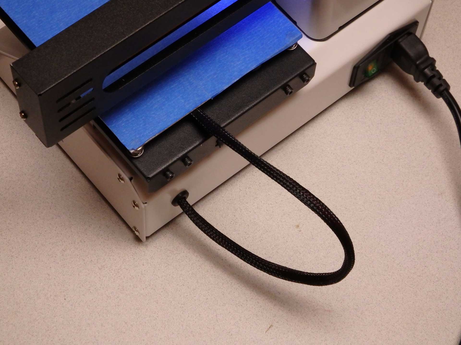 Ultimately, I decided I didn't like the...
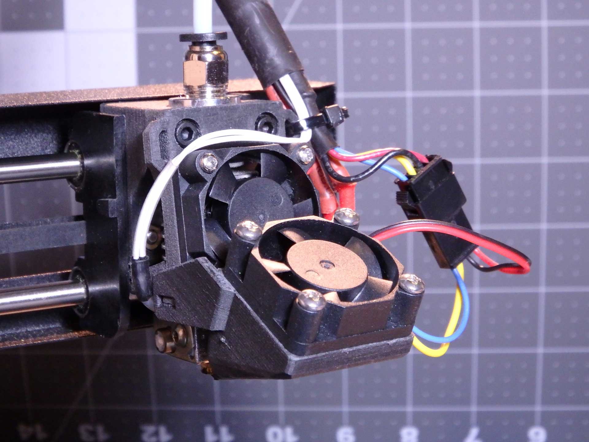 The files and installation instructions for this setup are now available on our Thingiverse Page. To download these files, please go to:
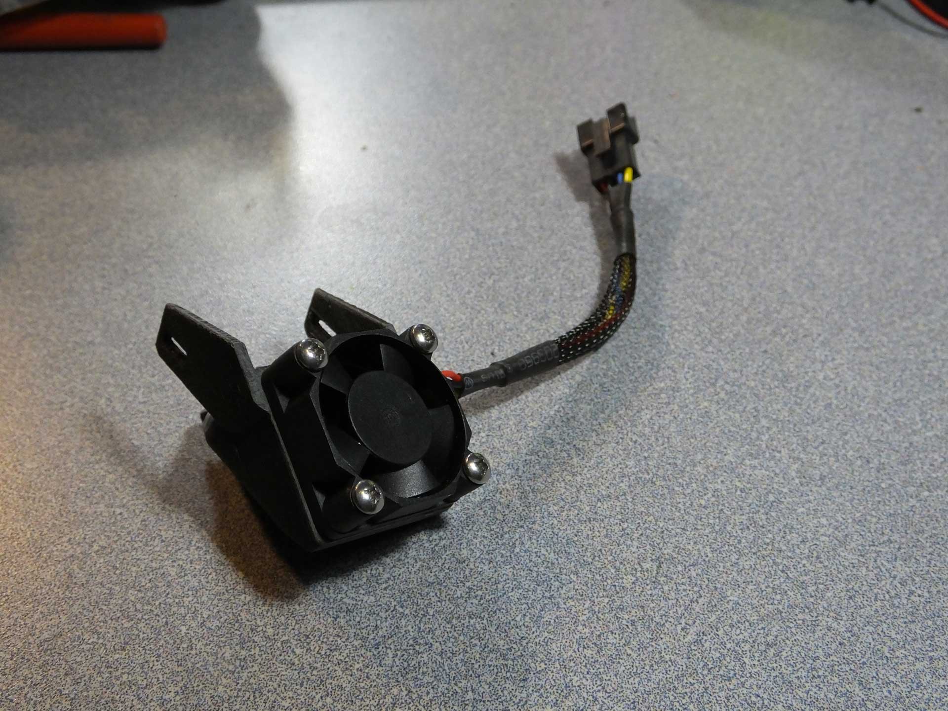
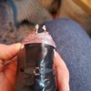
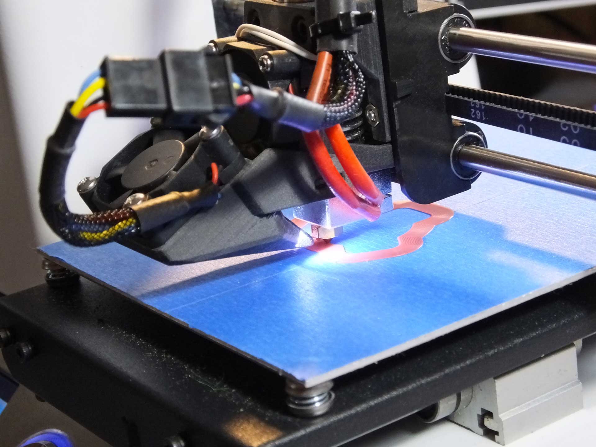 This is that the Part Cooling Fan looks like when it is removed from the E3DV6 Mount. Notice that it has a JST style connector so that I can swap in different fans and LED lights in the future as I design new styles.
 The outlet of this nozzle directs all of the air flow directly on the extruded plastic that has just exited the nozzle. This is intended for improving overhangs and bridges. You can also see the LEDs that illuminate the print beside the outlet.


 Myles Eftos
 Mark Rehorst
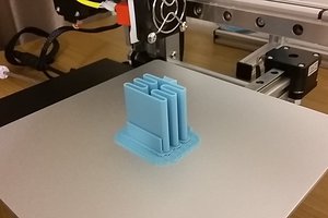
 Lukas Koch aka Ast
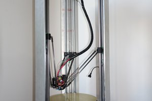
I got inspired by this series of mods and had to be part of it so I created a "belted Z- axis modification" since belted Z-axis in the new fashionable thing in the 3D printer world.
Kind regards/Stefan
https://www.stockholmviews.com/wp/prima-select-mp120-3d-printer-modifications/