Close
0%
0%

Rubidium Disciplined Real Time Clock

A Time Travel Beacon

Similar projects worth following
As recently stated on hackaday:
"A timepiece is rather a rite of passage in the world of hardware hacking"

Presenting: A personal time base.

Depending on current location, elevation, and velocity we all experience very real time dilation effects. Time does not pass at the same rate for everyone. The "Project GREAT" experiment in 2005 measured a 20 to 30 ns shift during a weekend family trip to Mt Rainier.
The idea is to continuously monitor and record cumulative time deviation.

This project uses a Rubidium atomic frequency standard to continuously track local time dilation effects relative to:
Electrical Frequency Controlled (EFC) Ovenized Crystal Oscillator (OCXO)
GPS with battery backup for internal RTC
WWVB US atomic clock radio frequency signal
(3) x Temperature Compensated RTC modules with independent battery backup

Thanks to comments from Doc Pedersen and nsayer, I ordered an Electrical Frequency Controlled (EFC) Ovenized Crystal Oscillator (OCXO) with TTL output to improve the short term stability.

It is a muRata OC2545-DT 10.00 MHz OCXO Crystal Oscillator.

OC2545-DT Datasheet

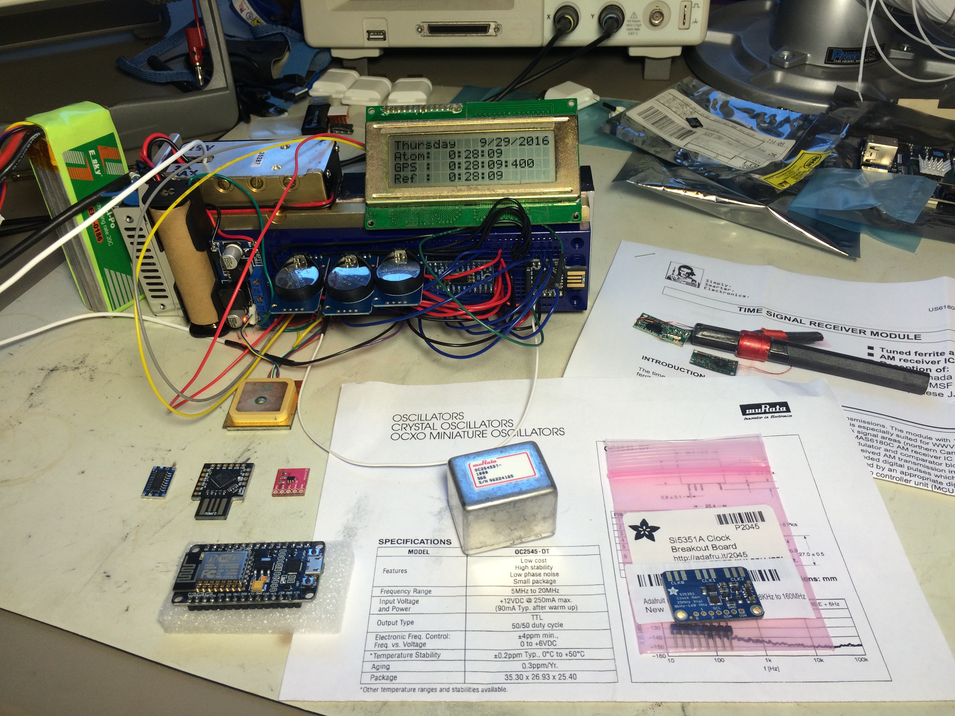
Thanks to the commenters I now have some new parts on hand:

muRata OC2545-DT 10.00 MHz OCXO Crystal Oscillator

12 bit i2c DAC board (To generate the control voltage - Delta Sigma w/Filter)

Adafruit Si5351 Clock Generator Breakout (To generate microcontroller clock)

RS232 to TTL converter board

ESP8266 ESP-12E NodeMCU

An I2C multiplexer board allows for more than one RTC module (Since these have a hard coded I2C address you can normally only use one). I went for three – One tracking GPS time, another tracking the rubidium standard, and the last one as a control or reference clock – without compensation.

An arduino knock-off compares the relative delay between the pulse-per-second outputs from the Rubidium standard, Real Time Clocks, and GPS.

After some defined time divergence, the RTC aging compensation register is updated to refine or maintain overall agreement. Essentially herding the RTCs so that their output stays within bounded agreement with the Rubidium standard and GPS.

This approach avoids editing the time registers directly, eliminating the possibility of corrupted writes.

All design details will be made available - My goal is 100% open source and open hardware.

This project runs on Arduino for which the libraries are under the LGPL.

sketch_sep14a.ino

A hack job - I will not deny.

ino - 9.30 kB - 09/23/2016 at 06:46

Download

View all 12 components

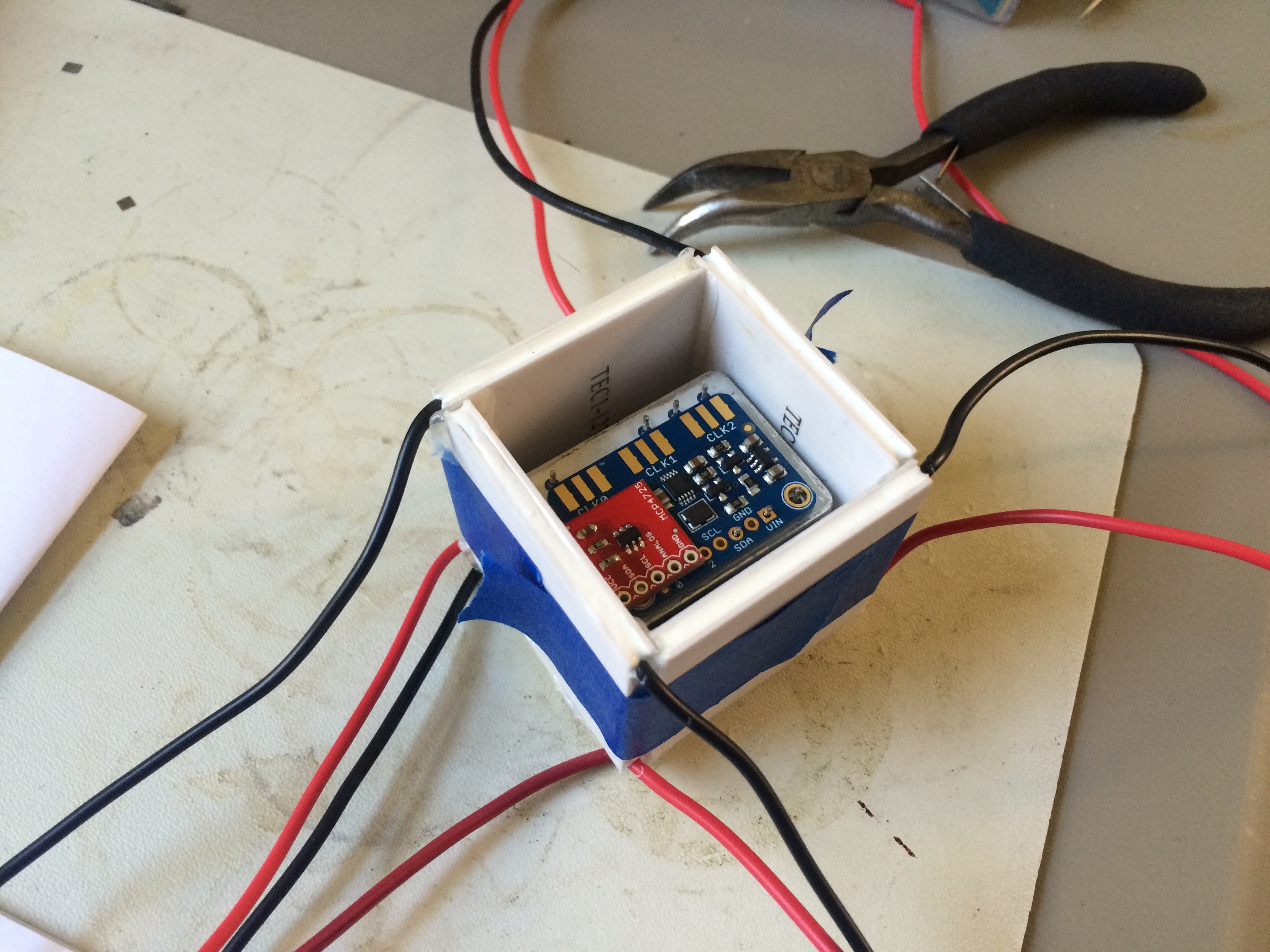
  • Double Oven - Made from Peltiers... Only Peltiers...

    oneohm09/29/2016 at 22:25 0 comments

    Since the oscillator requires at least insulation to insure a stable temperature - I decided to go a bit overboard and build an oven from thermoelectric modules...

  • ​New parts on hand!

    oneohm09/29/2016 at 00:59 0 comments

  • Untethered

    oneohm09/23/2016 at 04:41 0 comments

    Here it is – Running standalone. The firmware is in progress, no “herding” is happening yet, but at least it turns on.


  • Condensation

    oneohm09/23/2016 at 04:37 0 comments

    Tying everything together…


  • Too Much?

    oneohm09/23/2016 at 04:35 0 comments

    Then things started to get a bit out of hand… Adding in an I2C multiplexer board allowed for more than one RTC module. Since these have a hard coded I2C address you can normally only use one. I went for three – One tracking GPS time, another tracking the rubidium standard, and the last one as a control or reference clock – without compensation.

    Notice the new DC/DC converter – It allows input voltages from around 5-30V DC , currently wired into an old HP printer power supply @ 18.5V.

  • GPS is a Go

    oneohm09/23/2016 at 04:33 0 comments

    Conveniently I have a GPS module with PPS output to make testing a bit easier. A LiFePo4 18650 cell provides battery backup to the GPS module, maintaining its internal RTC, and configuration data.


  • About Time!

    oneohm09/23/2016 at 04:31 0 comments

    An arduino knock-off compares the relative delay between the pulse-per-second outputs from the RTC and the Rubidium standard. After some defined time divergence, the aging compensation register is updated to refine or maintain their overall agreement. Essentially herding the RTC so that its output stays within bounded agreement with the Rubidium standard.

    This approach avoids editing the time registers directly, eliminating the possibility of corrupted writes.

  • Are we tracking?

    oneohm09/23/2016 at 04:30 0 comments

    This brings us to the DS3231 Precision Real Time Clock Module:

    The Aging Compensation Register of this RTC module allows for fine tuning of the internal (temp. compensated) crystal oscillator by adding or subtracting small capacitors to the oscillator circuit. “One LSB represents one small capacitor to be switched in or out of the capacitance array at the crystal pins.”

  • Keep it Cool

    oneohm09/23/2016 at 04:26 0 comments

    As you can imagine some serious thermal management is required to run it continuously. Here is what I came up with, now directly powered from the lab supply:

    The fan and heat sink came from a CNC mini-mill control board that was gathering dust – some hack sawing quickly transitioned to angle grinding, drilling and some orbital sanding. Black sharpie for show, and now it looks good while running at a nice stable temperature, with adjustable fan speed.

    You can see the output on the oscilloscope – a short pulse, once each second. Usually referred to as PPS – Often available on GPS modules. Certainly interesting, but not much a of a feast for the senses, nor easily justifying the cost and effort to interested friends and family. Time to put it to use.

  • It's Alive!

    oneohm09/23/2016 at 04:25 0 comments

    Here it is ticking away connected to a bench power supply:

    Notice the power supply meters? Don’t worry – I’m using a larger DC-DC Buck/Boost converter to step it down for the 15V rail – the converter later failed while I was adjusting the output voltage however.

    Regardless – 21.1V @ 1.08A = 22.8W! This thing is a power hog, especially during initial warm-up (something like 5 min).

View all 15 project logs

Enjoy this project?

Share

Discussions

Classified wrote 01/29/2020 at 07:59 point

Is this working yet? I have an Rb module on order but as yet no sign of it. Think the problem may be a bad serial line as its not responding to commands so stuck on some weird frequency.

  Are you sure? yes | no

Adi wrote 02/27/2018 at 18:51 point

Can't believe I am the first to comment on remarkable progress! This is truly brilliant.

Would love to see the final working! So inclined to build one, thinking of a great use for it.. 

  Are you sure? yes | no

Similar Projects

Does this project spark your interest?

Become a member to follow this project and never miss any updates