 James
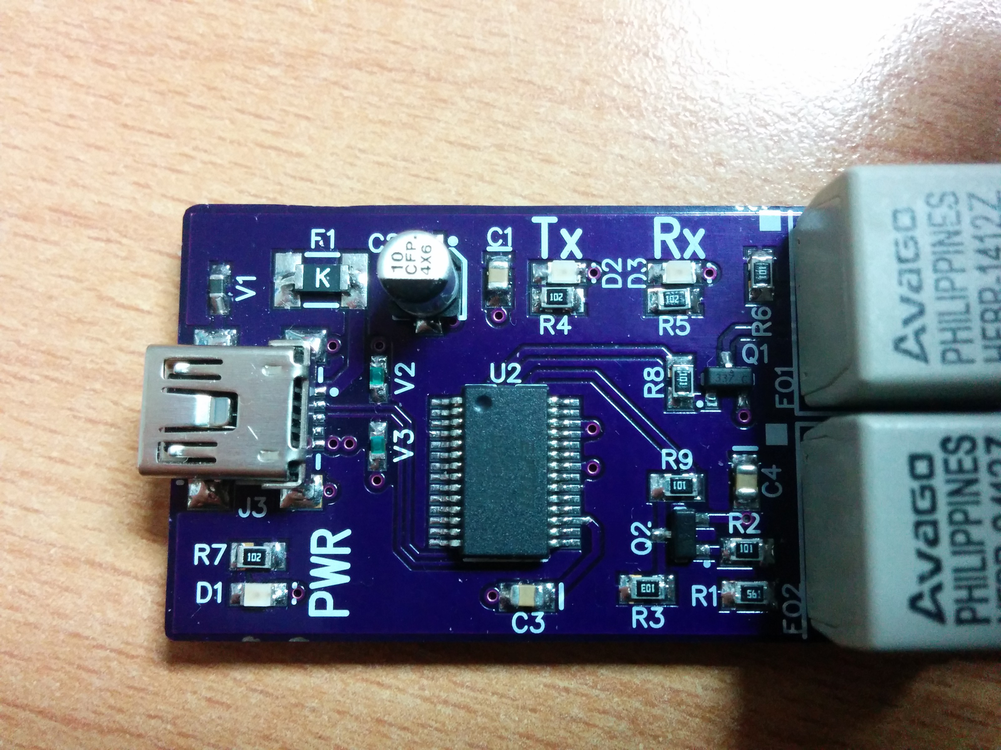
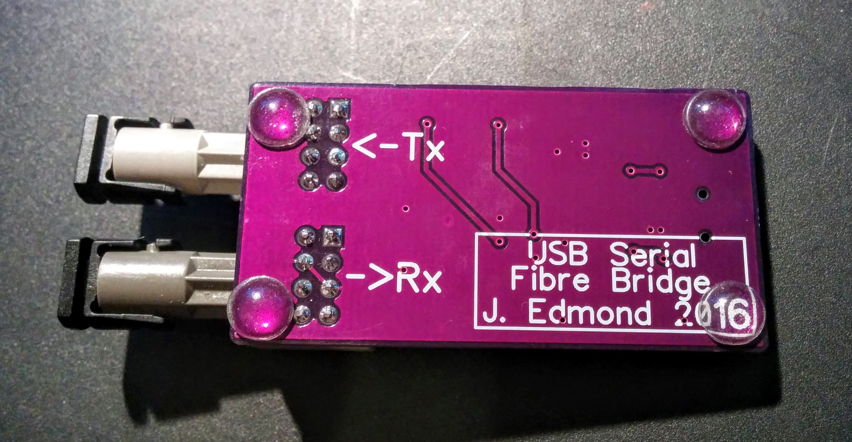
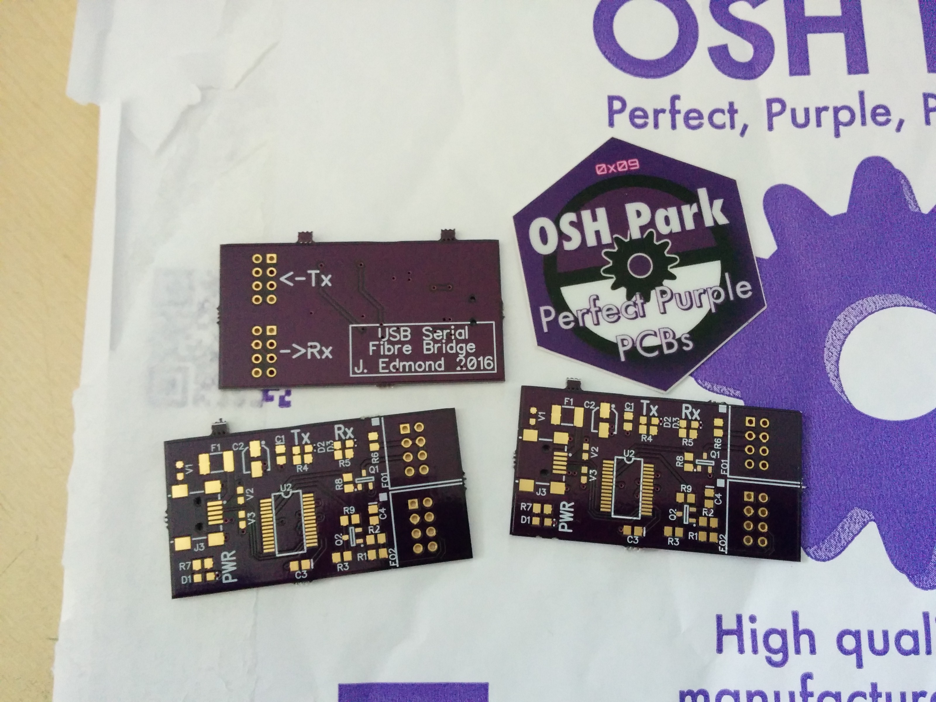
JamesA simple PCB to interface an FTDI FT232-RL IC with an Avago (now Broadcom) HFBR-x4xx fibre optic transmitter & receiver pair. The board has some simple protections and supporting circuitry as well as Tx, Rx, and power LEDs. A USB mini-B connector was used to talk to the host machine.
Fibre Optics
The choice of Tx/Rx pair was dictated by the fibres with which I would need to interface. The HFBR-x4xx family encompasses transmitters and receivers that work on the 820nm scale. They are available with ST, SMA, FC, and SC connectors and are compatible with various multimode plastic-clad-silica (PCS) fibres, including OM1 (62.5/125um), OM2 (50/125), 100/140, and 200um. For this iteration of the build, I used the HFBR1412Z transmitter and HFBR-2412Z receiver. These are ST connector parts, with plastic connectors. This choice was again determined by the fibre I had to interface with.
Protection
As a minimum, I decided to use:
- Overcurrent protection on the +5V input from USB
- A TVS on the USB +5V line
- ESD protection diodes on the USB lines
I'm hoping that this will give me a minimum level of protection against spikes, ESD, and general miss-treatment. Most of the protection was sourced from a Littelfuse app-note (which I don't seem to be able to find right now!).
For the USB Vbus protection I used a V5.5MLA0603 TVS diode, between Vbus and the shield. This is a 5V varistor diode recommended for this particular application.
For the ESD protection on the USB D+, D- lines I also turned to the Littelfuse datasheet, and selected 2x PGB10603NR low capacitance ESD protectors. Two discreet devices were selected, rather than one SOT-23, as this somewhat simplified PCB layout.
Supporting Circuitry
tbc...


 Łukasz Przeniosło
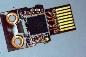
 Sam Ettinger
 Alex
Alex
 Bharbour
What distance will this work reliably? Thanks,