James
James-
Revision 2 - Coming Soon(ish)
01/06/2020 at 20:02 • 0 commentsSo, I've decided to resurrect this semi-dead project.
The original project served it's (very) short term goal of monitoring a serial data stream, and logging any anomalies to a CSV file. This was achieved using a laptop running a Python 3 script utilising PySerial (GitHub Repo, Documentation), logging to a CSV. I'll post this code, when I can find it. I have to warn though, it's not pretty!
Since "completing" the original project I have been thinking of a number of upgrades and improvements that could be made to the hardware. Namely, some sort of enclosure. Much preferable to covering the whole board with a length of 50mm wide clear heatshrink as I did previously.
The upgrades and changes I plan to make are as follows. Not all will find their way into the final iteration:
- Enclosure
- Hammond 1455 series extruded aluminium
- Likely candidate: 1455C801RD
- To use a custom PCB as end-caps. This allows for easy hole placement and continuity of ground/shielding
- Possibility to mount LED(s) using a right-angle SMT header connector between main and end board
- Switchable hardware inverters on FT232 data lines
- Allows for correction inversion introduced by the use of the fibre-optic link
- Switchable in hardware by the use of XNOR gates
- Should have (option of) LED indicator
- Inverters should be switchable per-channel, i.e. the option to invert only one, or both channels
- Likely to be set by a micro slide/ toggle switch
- PCB layout to accommodate both 820nm (HFBR-x4xx series) and 650nm (HFBR-x5xx series) digital transmitters and receivers
- Possible change to USB-C connector
- Probably unnecessary due to FTDI chip not supporting USB3
- Much finer pitch, therefore harder to solder
- Possibly less robust than USB Mini-B
I also plan to look at the protection available on the USB data & power lines. I want to ensure this is sufficient and appropriate for the application.
- Enclosure
-
PCBs Now Assembled
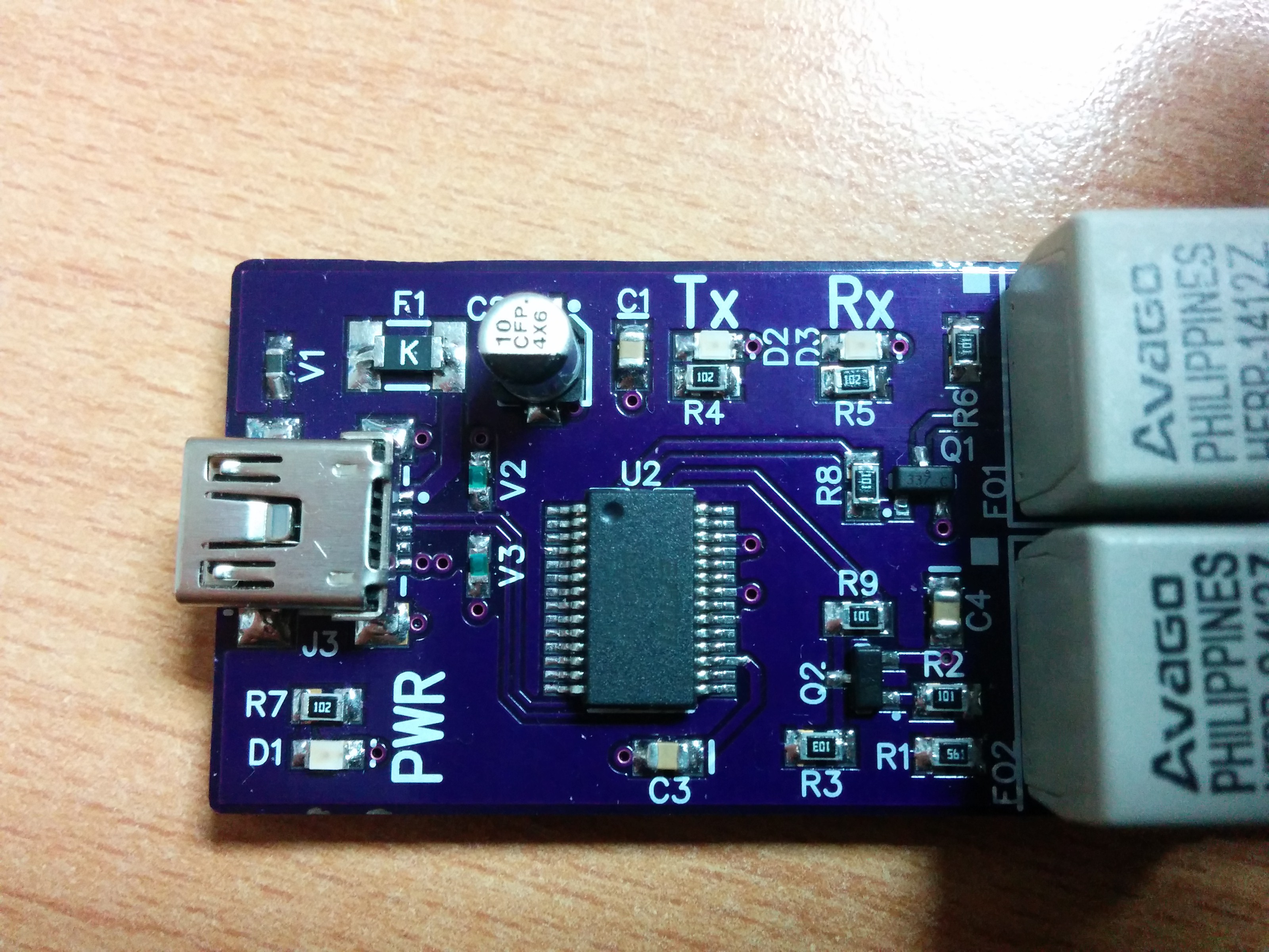
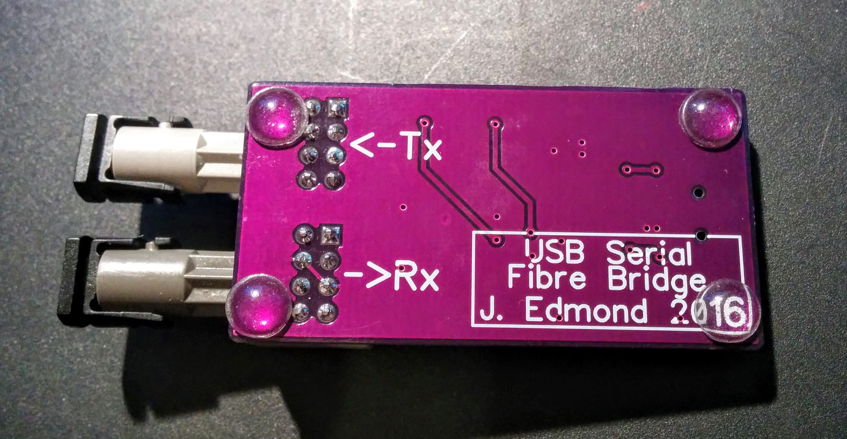
11/13/2016 at 16:22 • 0 commentsThe order for the components has come in and I can now assemble a test PCB.
All assembly was completed by hand, using a Weller WSP80 iron, with a fine point tip and Weller liquid flux. Most of the components were very easy to place, although the pins of the USB connector proved to be challenging.
I did realise a small mistake when assembling the board, that I seem to have used a 1812 footprint for the pollyfuse (F1), whereas it should have been 1206. The soldering was not quite up to what I'd have liked it to be, as I'm a bit out-of-practice!
I have added a few 5mm silicone feet to the bottom of the board, to keep it from flying around the desk. I intend to cover the entire PCB in 25mm clear heatshrink, but don't have any yet, so the feet will have to do for now.
All that remains now is to power up the board, and test functionality.
![]()
![]()
-
PCBs Have Arrived
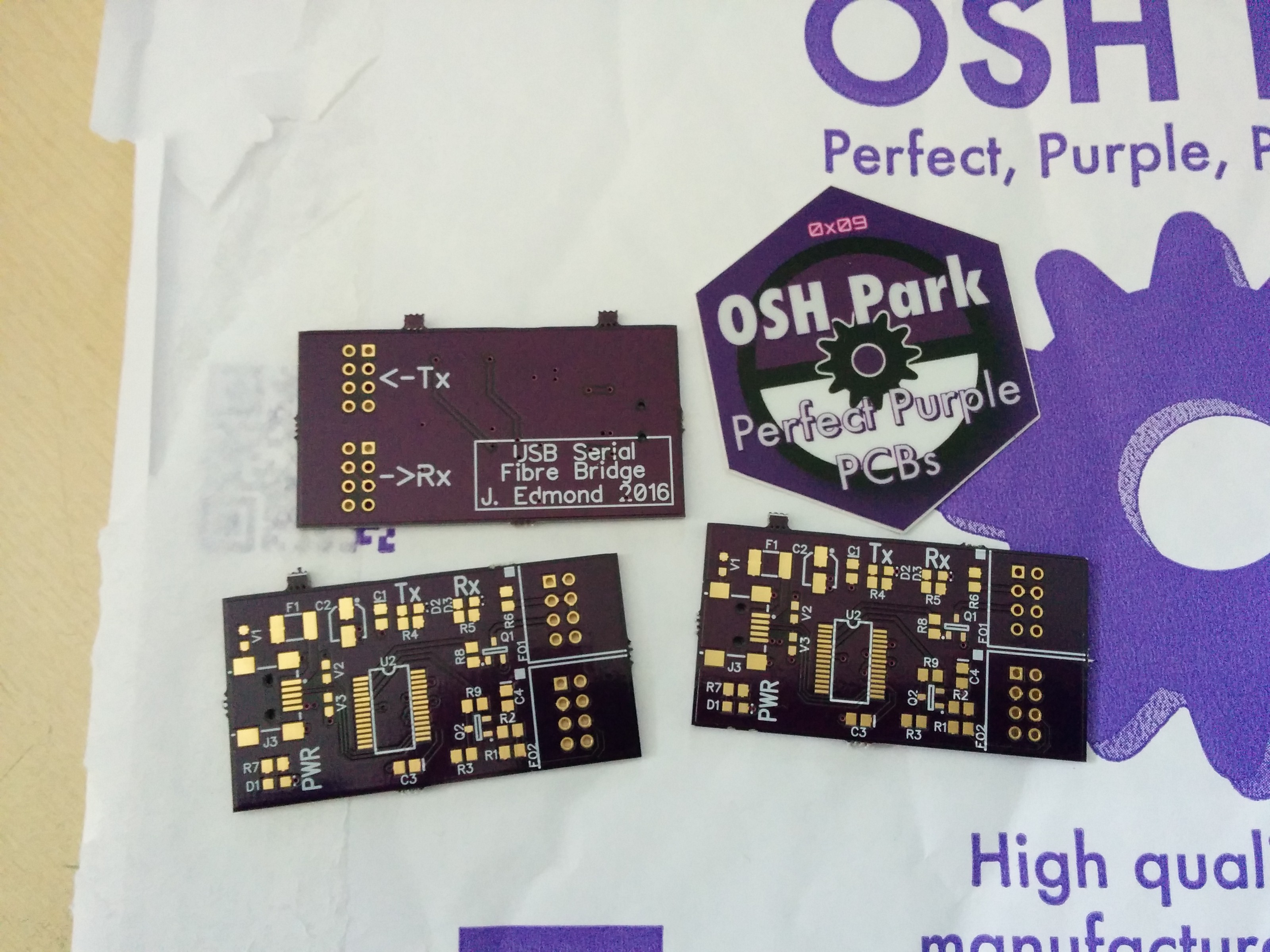
10/12/2016 at 08:38 • 0 commentsMy PCBs arrived from OSH Park yesterday afternoon. I am again impressed with the speed and turnaround time, including postage from the USA to England.
I now need to finalise the order for all the components, then begin building.
![]()
-
Log Entry: The 1st Itteration
09/27/2016 at 14:15 • 0 commentsA few changes have been made to the PCB to simplify the routing. The FT232 has been moved slightly toward the lower edge of the board.
I have now uploaded the schematic (including Bill of Materials), and sent the first order for PCBs to OSH Park.
-
First Log Entry: The Beginnings
09/26/2016 at 19:36 • 0 commentsThis project is being developed as a side project to enable me to debug a piece of industrial control hardware that uses serial-over-fibre communications.
The schematic capture and PCB design for this project has been done using DipTrace. The 3D models used for the HFBR-1414 & HFBR-2414 fibre optic transmitter and receiver are of my own creation, the rest are stock DipTrace 3.0 models. The 3D model is not intended to be a highly accurate representation, but a guide.
The transmitter receiver pair were chosen based upon the requirement to be able to interface with OM1 (62.5/125um) or OM2 (50/125), terminated with ST type connectors. This is fairly standard for use with industrial control, the intended application of this board.
First images of rev. 1 PCB uploaded. I intend to upload a schematic shortly.
FT232 - Fibre Optic Interface
A minimal board to interface the FTDI USB serial converter with a pair of fibre Tx/Rx.