Close
0%
0%

ublox NINA-W102 minimal breakout

A minimal breakout board with breadboard friendly spacing and self locking solderless headers exposing all the pin's of this ESP-32 module

Similar projects worth following
The goal of this project is to have a minimal breakout board for prototyping with the NINA-W102 module from ublox, which is an ESP-32 half the size from the usual ESP-32 modules, in projects or use it directly as trough-hole module.
Design goals are simplicity and minimalistic design without any fancy stuff on it but exposing every PIN of the uC. It shall be breadboard friendly and allow to be plugged in to the middle while still allowing the outer sides to have free slots for jumper wires.
To not restrict the usage as most finished dev modules do, it will expose VCC and VCC_IO with a cuttable bridge that if needed VCC_IO can be feeded with a different Voltage level (by default the bridge configures to have 3.3V for the IO lines.
It will feature RESET and BOOT button if needed (IO exposed so can be left unpopulated) and a power indicator which shows if there is power on VCC (which can also be left unpopulated).

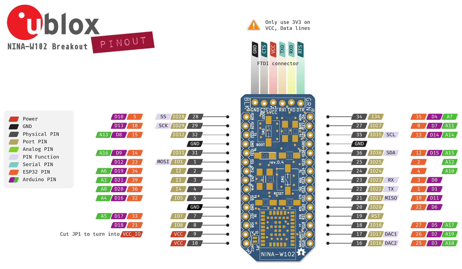
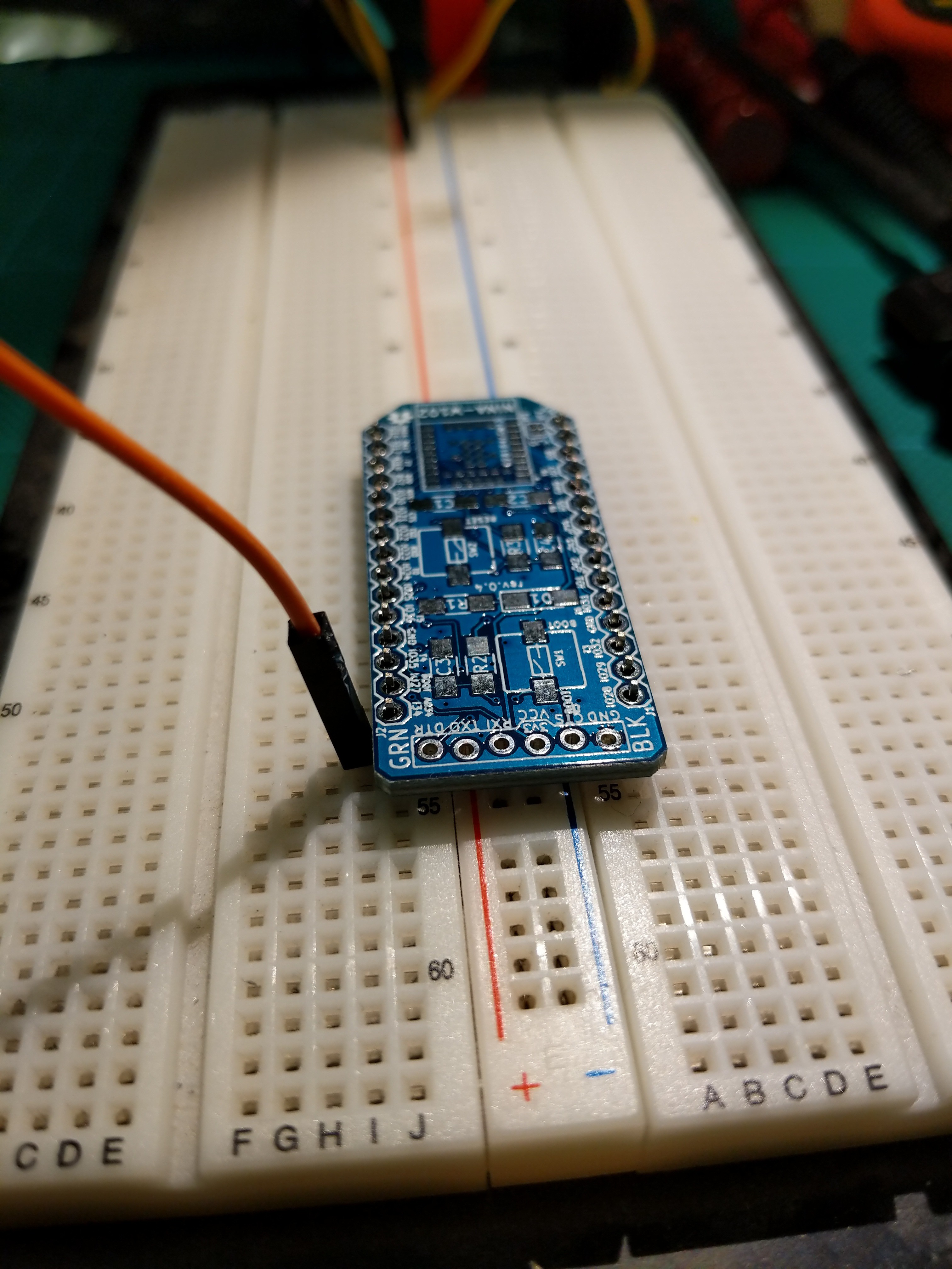
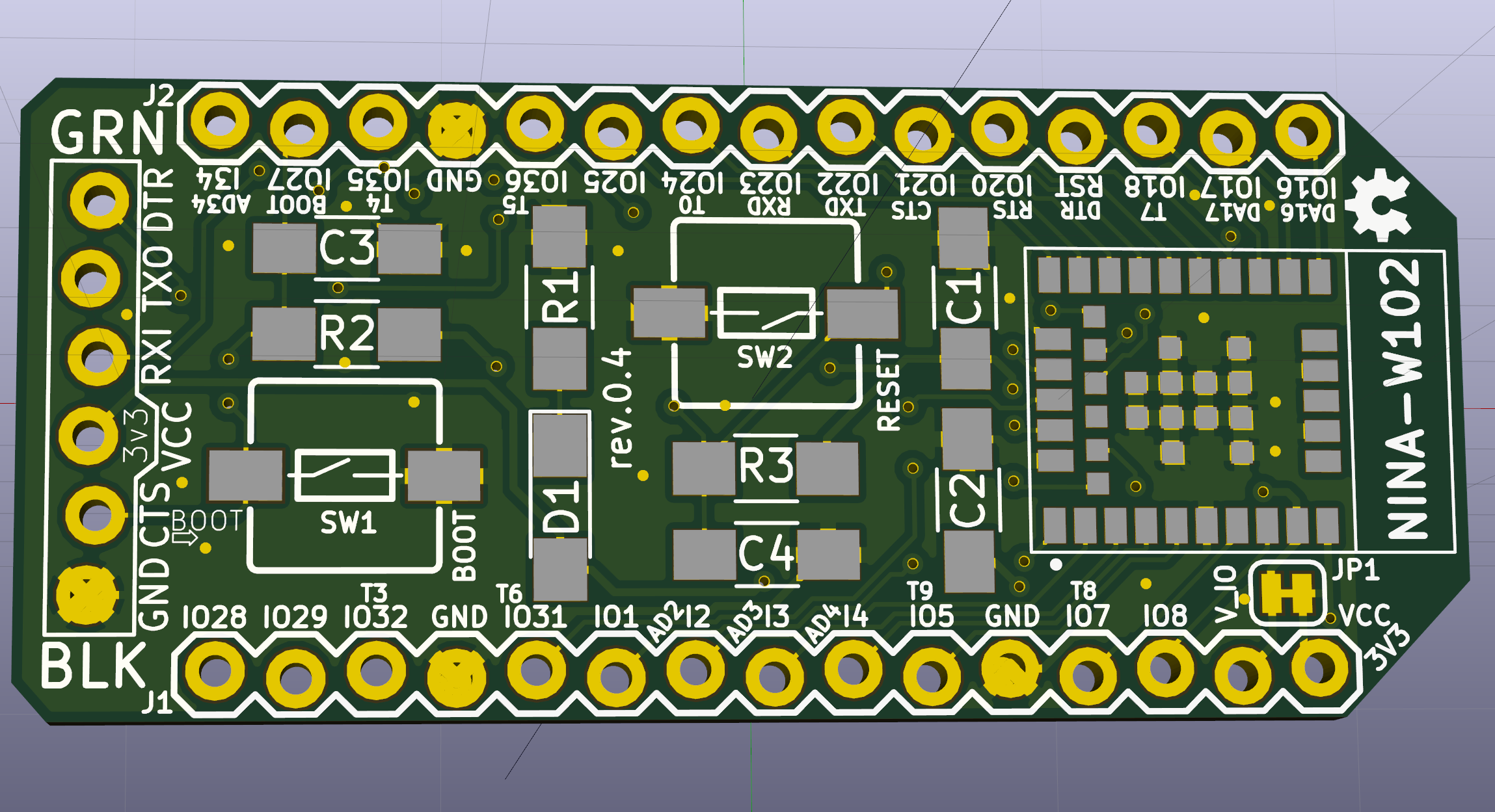
In the process of designing a conference badge and facing tight deadlines, we need a minimal breakout board for the uC we are using on it in order that the firmware team can already start working on it without having to wait for the first hardware prototype of the full board. This way they can directly use the NINA-W102 instead of having to port the code later on and connect it together with sensors that are on breakouts as well and simulate something that is closer to the real thing.

The source of the KiCAD files is on my github and during PCB layouting I will keep the branch NINAPCBGround up to date as much as possible with frequent commits.

https://github.com/rac2030/breakout-boards/tree/NINAPCBGround/ublox_NINA-W102

If you have any suggestions or review comments, please just shoot them to me as this is my first try in using EDA tools for designing a custom PCB.

Please keep in mind that I do fast iterations so it might change overnight as I do this in my free time and mainly in the night when I'm not working on my day job or have to care about other duties.

Adobe Portable Document Format - 1.40 MB - 05/29/2018 at 23:21

Preview
Download

Adobe Portable Document Format - 75.39 kB - 05/29/2018 at 23:20

Preview
Download

Adobe Portable Document Format - 244.18 kB - 05/03/2018 at 08:59

Preview
Download

NINA-W102_minimal_breakout-rev.0.4.pdf

Schematics of the board

Adobe Portable Document Format - 83.75 kB - 04/21/2018 at 14:59

Preview
Download

  • 1 × NINA-W102 U1 - ublox NINA-W102 esp32 module with onboard antenna
  • 2 × 100nF capacitor C1, C2 [1206 package]
  • 2 × 1uF capacitor C3, C4 [1206 package]
  • 1 × GREEN LED D1 [1206 package]
  • 2 × 01x15 male header J1, J2

View all 8 components

  • First production run

    Michel Racic05/29/2018 at 23:30 0 comments

    The design has been finalized and the first run of 120 pieces is now in production.

    A project website has been created which contains all needed info to use it and can be found at http://rac.su/ninab

    Thanks to Gonzalo, we have now a nice Arduino style pinout map ;-)

    The old Duck Tape Approved has been replaced with another version as we did not get any reply about the licence of the original picture and if we are allowed to use it. While it is derivative work and not exactly the same, I did trace parts of a logo from a website and we asked the author but never got a reply, so better stick with an image which is under a CC licence that we can use.

  • First simple test

    Michel Racic05/03/2018 at 11:17 0 comments

    I conducted the very first simple test, using the generic wifi scan examples from the ESP32 package in Arduino and choosing the board "u-blox NINA W10 Series (ESP32)"...

    I did not find my other serial adapter which has the correct layout but this one works as well with some cables. Otherwise the programmer would stick with the snapfit pcb socket perfectly without soldering any headers/sockets and it does work quite well with just holding the dupont cables as the housings press it against each other like in a row connector.

  • First prototype assembled

    Michel Racic05/03/2018 at 08:40 0 comments

    First hand assembly of the prototype is done, now we can move on to start testing and developing firmware for it ;-)

  • First physical boards arrived from PCBWay

    Michel Racic05/02/2018 at 21:39 0 comments

    Firs prototype did arrive from PCBWay and looks great so far.

    The breadboard layout worked out as designed and only occupies 1 column on each side. The snapfit design (courtesy of an old SparkFun blog post I did read) for the headers seem to work very good as solder assistant but Gonzalo measured bad conductivity when not solder so might have to adapt it later and make the shift a little bigger). The Font has some small errors that need to be corrected for it to look nicer but for now we can conduct the first assembly by hand to test the functional parts of it. The sample from OSHPark is still on the way but it will be interesting to compare the print and pad quality of the two suppliers.

    The NINA module is a tiny bit small and hand soldering it might be a bit challenging as I never did solder SMD parts so far and this entire build is my hello world in designing a board with EDA software from schematics to PCB layout and then go trough the process of actually manufacturing it as finished modules to be used in the MakeZurich hackathon which is coming up pretty soon.

  • First prototype sent for fabrication

    Michel Racic04/25/2018 at 00:29 0 comments

    After a couple of small review cycles, I have now a first version that has been ordered as a test batch from OSHPark and PCBWay to see and compare and test it out of course ;-)

    Here are the renderings for the breakout in rev.0.4 which is also pushed to github

    And gonzalo made new design mocks of our main use case for this module which look pretty cool

    the module in the bottom is the NINA breakout, all PIN's except the ones we have in use by the badge motherboard are exposed to the sides.

  • Rev.0.4 waits for prototype production

    Michel Racic04/22/2018 at 21:47 0 comments

    After adding some more ground vias, fixing problematic traces and vias and adding more pin labels, this is likely the revision which I send to OSHPark next week if there are no review comments.

    CTS from the serial header is connected to the SYS_BOOT pin (for that the ⇨BOOT behind it on the silk) but on the sides (J1 and J2) all PINs of the NINA-W102 module are exposed and there the CTS label points to the actual UART_CTS pin.

    After a design decision made on another project (https://hackaday.io/project/152901-iot-conference-badge), this board will have not just a life as breadboard prototyping breakout but will be used as a module with stackable shields on a conference badge. This gives the attendees the possibility to just detach that part from the header (not soldered) and use it for their projects.

    This is a short draft from @Gonzalo Casas  of how this badge looks like from the dimensions, the thing on the top is a Waveshare 2.13" EPD module.

  • PCB drafts

    Michel Racic04/22/2018 at 00:27 0 comments

    Attached images of the PCB rev.3 board after having a couple of design iterations and got feedback from reviewers

  • Schematics

    Michel Racic04/21/2018 at 14:58 0 comments

    Schematics has been created with the help of the datasheet and the system integration handbook of the NINA module.

    Current version is rev.0.4 which has incorporated some feedback I got from engineers reviewing my design.

View all 8 project logs

Enjoy this project?

Share

Discussions

Similar Projects

Does this project spark your interest?

Become a member to follow this project and never miss any updates