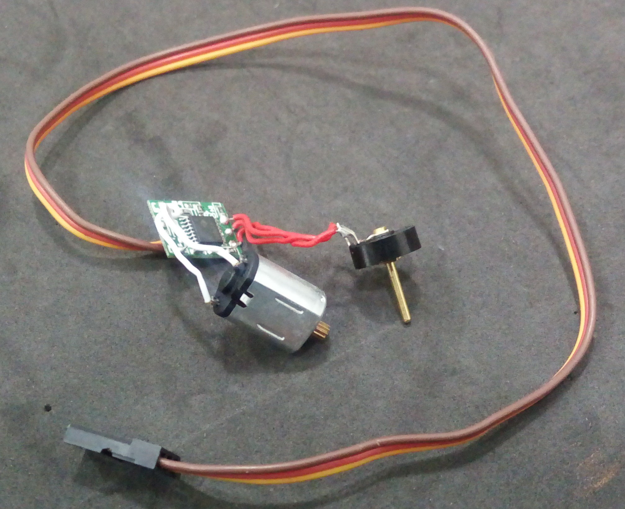
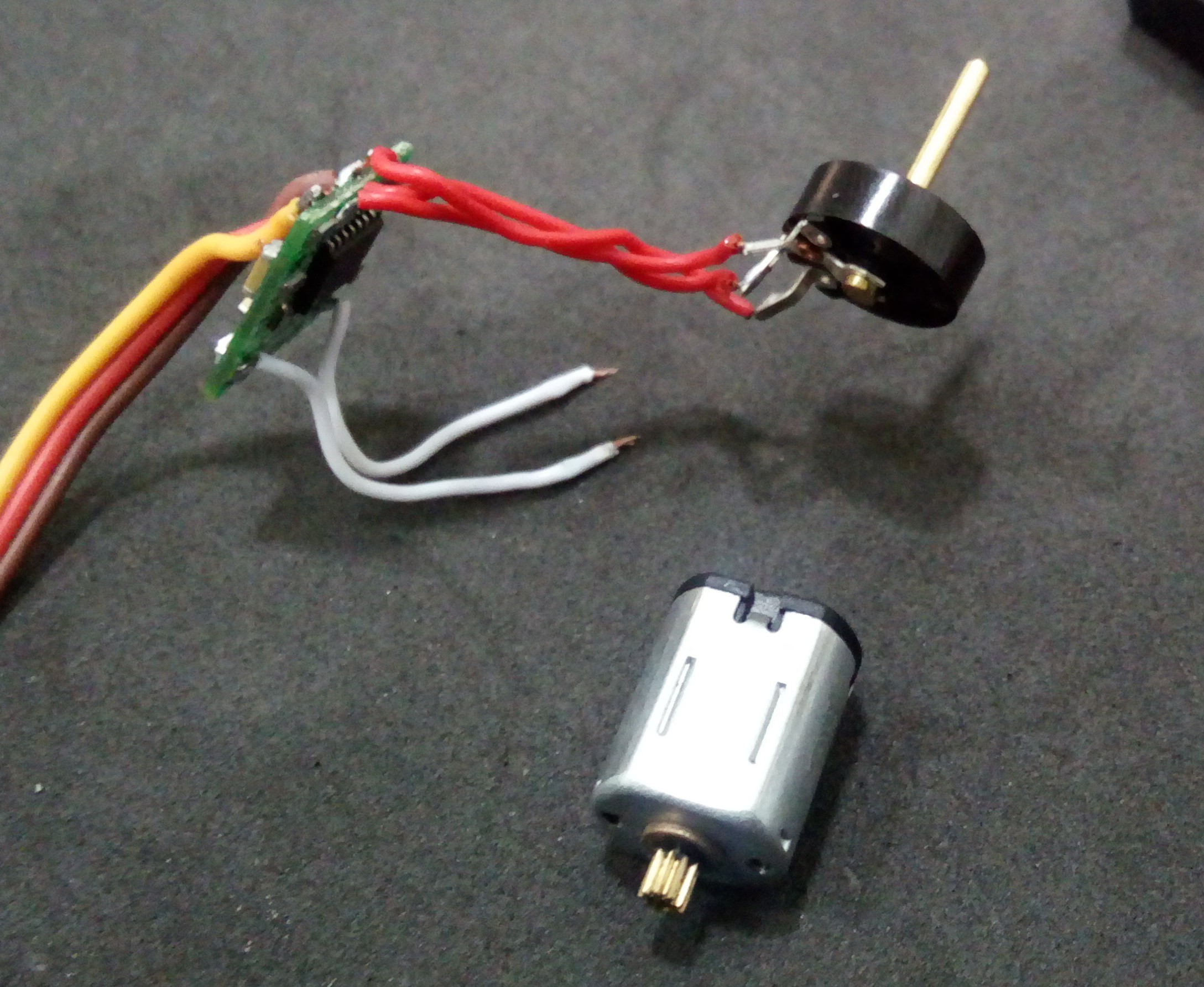
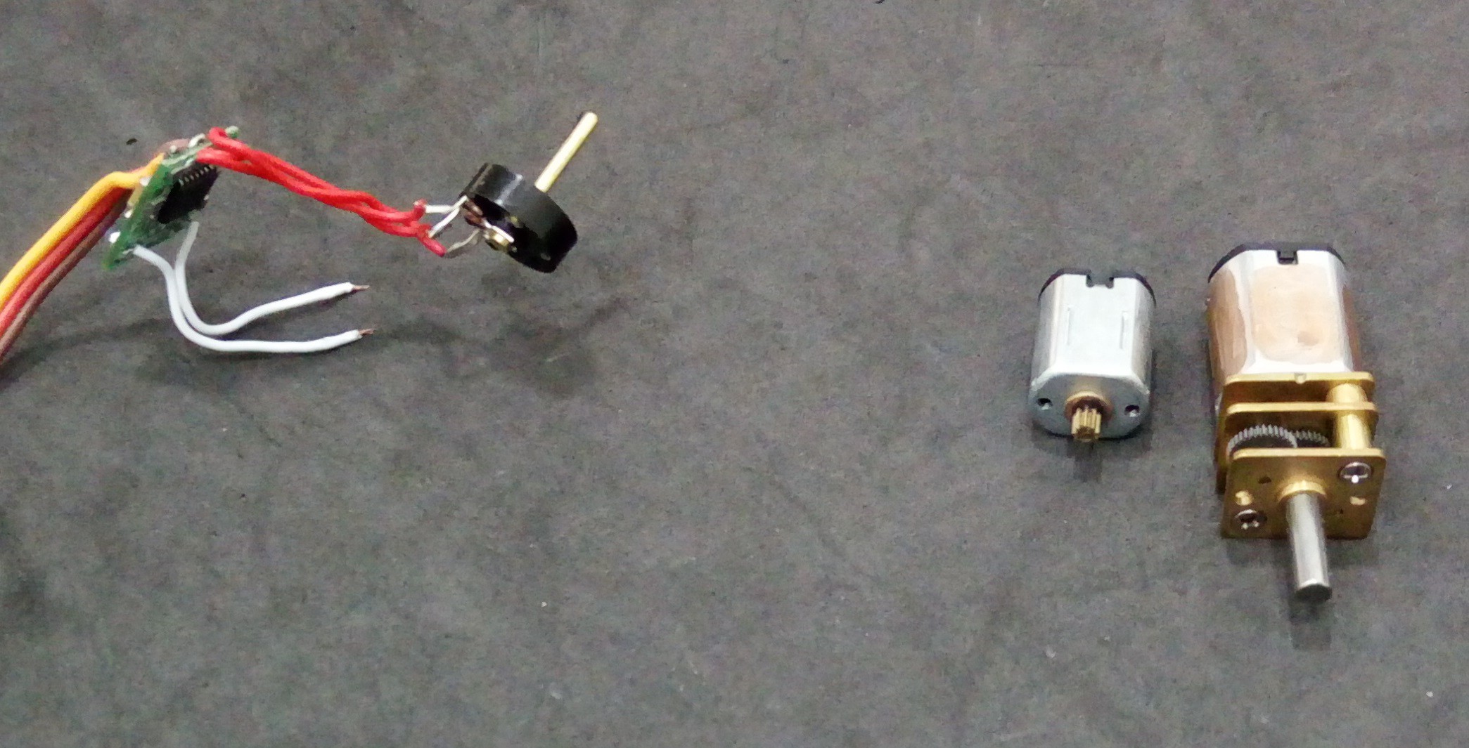
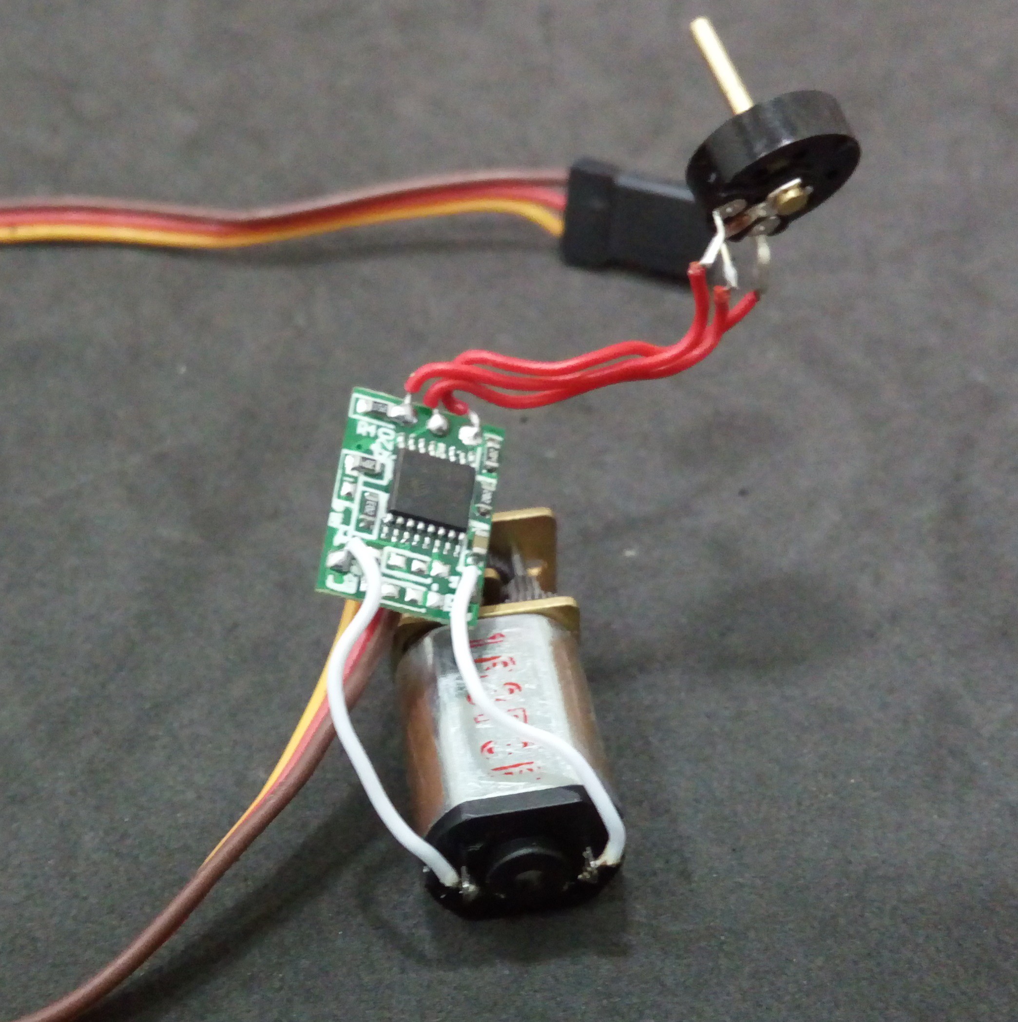
Close
0%
0%

3D printed mini linear actuator

Need a mini linear actuator that is easy to print and implement in your robotics DIY projects?
We got you

Similar projects worth following
The linear actuator is a subproduct of a previous project and we tought it would be useful to other makers. So, the idea is to make something like those Firgelli micro actuators but yourself and with the added bonus that you can integrate the inclosure of the actuator to the body of your robot or project.

Assembling process

We hope to improve it and keep it to the bones so other can implement it, sugest improvements and make something useful together
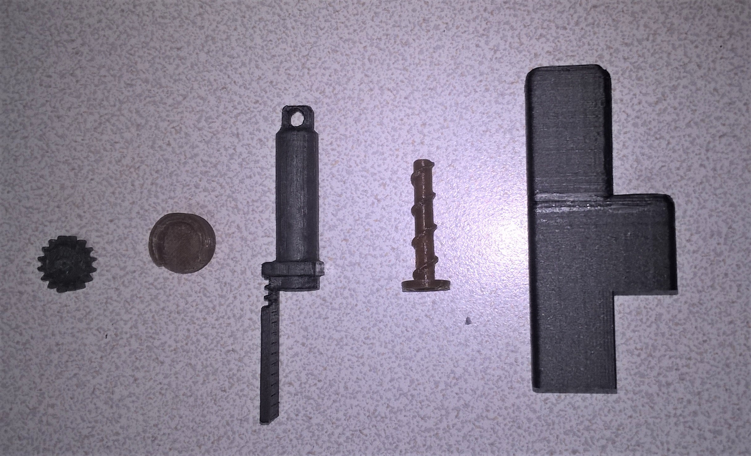
Schematics

Licensing

As everything on Hackaday, all that is published here is for grabs and to make your own. If you plan to sell it, please make it really different or had functionality to it. We know all of that its obvious and already written but we wanted to say it explicitly.

curaprofile - 2.95 kB - 08/22/2018 at 19:38

Download

step - 80.42 kB - 05/31/2018 at 12:54

Download

fusion - 91.64 kB - 05/31/2018 at 12:54

Download

step - 12.12 kB - 05/31/2018 at 12:54

Download

fusion - 67.94 kB - 05/31/2018 at 12:54

Download

View all 19 files

  • 1 × Tower Pro MG90S Metalic Micro Servo Dimension: 22.8×12.2×28.5mm, Stall torque: 1.8kg/cm (4.8V); 2.2kg/cm (6.6V), Operating voltage: 4.8V~ 6.6V
  • 1 × Arduino Uno R3 Microcontroller: ATmega328P, Operating Voltage: 5V, Input Voltage (recommended): 7-12V.
  • 1 × Polulu 100:1 Micro Metal Gearmotor
  • 1 × Hall effect sensor U58602 https://www.adafruit.com/product/158
  • 2 × Mini Magnet

View all 8 components

  • World Maker Faire 2018

    Giovanni Leal10/08/2018 at 16:37 0 comments

    Hi!

    it has been a long time o there is a lot to tell you about.

    First, we made the ¨hall sensor 3d printed mini linear actuator¨ working. It works great and it much much easier to print and assemble that the previous one, less pieces, ligther and cheaper. So we will publish the files in due time or if anyone specifies a request.

    Also, we were at the WMF at New York and it was awesome!

    We met with:

    Curt https://hackaday.io/project/159098-stomach-acid-powered-smart-pill

    Kent https://hackaday.io/project/94611-gutters-to-gardens

    Johannes https://hackaday.io/project/120377-3d-printed-strain-wave-gear

    and Michael https://hackaday.io/project/20165-linear-delta-robot-3d-printed

    All of them had great porject and most importantly willingness to contribute and share so check them out and drop a like.

    We had the opportunity to be a part of a live tweet in hackaday so check that out also:

    https://twitter.com/hackaday/status/1043532657437470720

    Thank you everyone that took interest in this project, that got us to the semifinals and has made us learn a lot.

    So as always feel fre to ask anything.

  • Fresh start

    Giovanni Leal08/31/2018 at 17:26 0 comments

    First of all, we are going to visit the WMF at NYC. Hackaday has a slot to speak about the Prize and they asked us if we would like to speak a little bit about the experience and we said yes! If you are going to be around the area come by and say hi.

    So about the current actuator.... we had an idea.

    We always tought that the design was pretty clunky, big, lots of mechanical components... and it comes for the thing that makes it "great", the potenciometer.

    That thing its so hard to calibrate.

    So the current desing we take the H bridge and the "position sensor"from the servo. So if we are going to replace the potenciometer.... no more H bridge. So thats an easy fix: https://www.adafruit.com/product/1438 

    We have use this board before in the OWI arms project and it works great, also the code its much much cleaner than having to simulate you have a servo attach.(also availabel for feathers)

    So the potenciometer? we need something thats not mechanical so, hall sensor.

    We tried out hall sensors from Adafruit and they work great as a digital ( you need a resistor) or analog sensor. Keep in mind the polarity of your magnet because that matters.

    So the lighter, thinner, simpler, less patrs...er linear actuator:

    Please let us know any sugestions... we will print it try it out and if it work... share the files with you.

  • How to print the actuator

    Giovanni Leal08/23/2018 at 14:28 0 comments

    Hi!

    So we have been asked how to print the actuator because theirs keeps breaking.

    To address this concern we have uploaded the profile file from Cura in the file section(Perfilimrpresion.curaprofile) for you to implement it. Fare in mind that this configuration is with a 0.3 tip in a 30x30x30cms printer, you may want to adjust that.


    It's in spanish but you'll get it.

    Also two things, first we are thinking about redesigning the actuator in a way that yeah it will have like 5 cables BUT!!! it will be like so much slim so you can choose what works better for you.

    Second thing, we have been invited to participate at the World Maker Faire. Like for 3 minutes in a panel but we tink its great! When we get more details we will share them with you.

  • Update on the silica gel

    Giovanni Leal08/15/2018 at 22:43 0 comments

    So, remember when we said to all of you that you should put your filaments on a box with the biggest bag of silica gel that you could find? 

    About that... DON'T DO IT!

    Really bad advise and sorry about that. The silica gel has a limit of water that can absorb and we are on a shared office space with full blown air conditioner, the silica disolved itself and became an oily liquid. This was all over our filaments and when it gets on the gear of the printer extruder, it grinds.... so a lot of unfinished prints.

    The solution, we cleaned out all of it and replace it with rice.

    Once every two weeks we take it out and let it rest on the sun. This happens because we dont have a lot of rotation on some filaments so....

    However take this advise with a grain of salt( no pun intended), its working and we will keep you posted.

  • You want change the speed of the actuator?

    Jonathan Díaz08/13/2018 at 16:57 0 comments

    What will happen if you want to change the speed of the actuator? Sometimes we need to control some factors of our design for some types of applications, simplifying it could be said: changing the engine is the correct way, but we have found another way.

    Whith modifying the steps of the screw can get good results, this can be done from the model. How? for many the answer is obvious but we will show how to do it with the designs we have made and are available for download.

    In the Files section there is a file called Piston, this is available in various formats, We work in Autodesk Fusion 360, thus the instructions are made for this application but can also be used for help in other software. Changing the steps of the screw causes it turn faster or less quickly, in the post the screw have a five revolutions in the coil function so with other value the result would look like this

    Also you have a change the piston in the same file,

    If you want more details with how to do it, go to instructions section there are a step by step of the process.

  • Finals Entry

    Giovanni Leal08/09/2018 at 19:39 0 comments

    Hi!

    We wanted to share the video for the finals here also.

    Have a great day!

  • Weight lifting sesion

    Giovanni Leal06/21/2018 at 22:22 2 comments

    Hi everyone. So yesterday Alvaro Villoslada asked us how strong is the actuator and..... we didnt know. So the best way we found to measure it was to pull up weight until we broke it. 


    It worked great until 450 grs. 

    500grs broke it. Thats with our design and the wway we print the screw. Hope to see people pulling more!

  • Thank You!

    Giovanni Leal06/15/2018 at 20:12 0 comments

    Hello everyone, Jonathan and i wanted to say thank you for all the support and attention that made this project get to the finals. This project has given us so many thing like joy, peer recognition and a challenge.

    To the people that asked us about the finger, that is a part from an old version of this project:

     So that is why the finger exists. 

    We will continue the project as long as any of you sees an aplication and we can chip in to make it better. So feel free to use it and to ask any question or suggestion. 

    We will see you again at August at the Human - Computer Interface Challenge!

  • Application

    Jonathan Díaz06/01/2018 at 21:57 0 comments

    This is a simple application of the mini linear actuator, in this case is a robotic finger used in a robotic hand

  • It's alive!

    Giovanni Leal05/16/2018 at 16:32 0 comments

    Hi, we finally printed out and made it work as you can see on the next video.

    The build instructions are pretty self explanatory, however in the video we skip the servo dismouting part and glueing the gear to the potenciometer, let us know if you need a video of that also.

    About the humidity, this was the solution:

    A big box with lots of silica in it.

View all 12 project logs

  • 1
    The potentiometer and control board

    The components are obtained from Servo Motor, the servo is disassembled and  you extract the potentiometer and the control board

  • 2
    Change the internal motor and use the Pololu 100:1 Micro Metal Gearmotor

    The internal motor of the micro servo should be replaced, in his place its added  the Pololu 100:1 Micro Metal Gearmotor

  • 3
    Print the components

    Now print the components, there  are a five components, in the files section you should find the parts in different formats, you can download and print directly the .stl's

View all 8 instructions

Enjoy this project?

Share

Discussions

kevin.chamoin wrote 05/18/2022 at 07:33 point

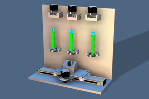
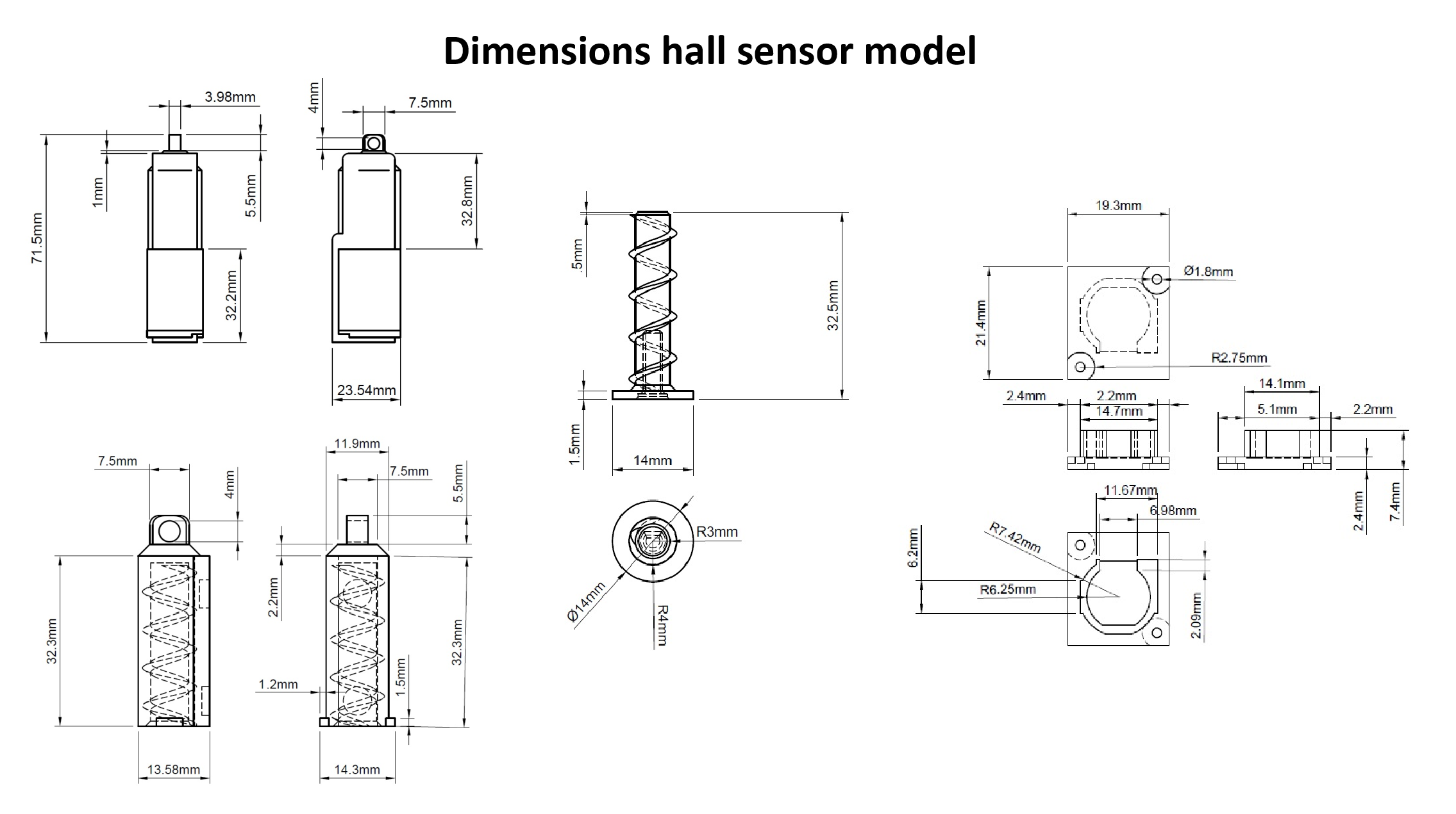
Hi, do you have files for the hall sensor model ? 

  Are you sure? yes | no

Kutay Kılıç wrote 11/16/2020 at 11:56 point

Hi. I know this is a very old topic but I hope you guys are still interested about the topic. Do you think you can still get optimal performance if you increase the length of the printable components? (Not too much maybe 2 or 3 centimers more.) That would be perfect for the project I am working on.

  Are you sure? yes | no

Alvaro Villoslada wrote 06/20/2018 at 07:27 point

Nice design! Just curious, have you measured the force the actuator delivers?

  Are you sure? yes | no

Giovanni Leal wrote 06/20/2018 at 19:42 point

Hi Alvaro, glad you like it!

We'll get rigth on that and post a log just for you. See you then.

  Are you sure? yes | no

Michael Graham wrote 06/03/2018 at 11:30 point

Very slick! I have been working on a 3d printed linear actuator of my own and it had not occurred to me to disassemble the servo.

  Are you sure? yes | no

Giovanni Leal wrote 06/06/2018 at 13:59 point

Hi Michael. What a great build!

It's great to meet people with similar ideas, hope some of our project can enhance yours. 

  Are you sure? yes | no

Ray Constantine wrote 05/31/2018 at 03:23 point

Are you dissembling the servo to get the feedback potentiometer?  Can you not use some other pot?

  Are you sure? yes | no

Jonathan Díaz wrote 05/31/2018 at 14:24 point

Hi Ray. Yes we found the servo a cheap way to get a H bridge circuit and a potenciometer at once so thats the way we did it. However you could find the pieces and build it but we think it would be the same price and a little more time consuming. However it would be a great exercise of design.

  Are you sure? yes | no

albertson.chris wrote 05/31/2018 at 03:18 point

Thanks.   The best way really is to put the files on  Github.  Then just post a link.  then you don't have to keep uploading and githum keeps the entire history of you project

  Are you sure? yes | no

Jonathan Díaz wrote 05/31/2018 at 14:14 point

Hi Chris, the files are ready in .step and .f3d formats, we hope you find them useful.

  Are you sure? yes | no

Ray Constantine wrote 05/31/2018 at 03:12 point

I think this is a fantastic project.  Being able to incorporate the components within other designs makes for much better efficiency and will look better too.  I'm looking forward to seeing how you actually assemble it with all components because I'm finding it hard to follow the video.

  Are you sure? yes | no

Jonathan Díaz wrote 05/31/2018 at 14:25 point

The next post will be the disassembly of the servo. Thanks for the feeback Ray!

  Are you sure? yes | no

albertson.chris wrote 05/30/2018 at 17:53 point

Do you have CAD files?  Yes I can import and convert STL but STEP files or the like would save people quite a lot of work.

I have some ideas I'd like to try to add strength and reduce weight

  Are you sure? yes | no

Giovanni Leal wrote 05/31/2018 at 02:53 point

Hi chris. 

Thank you for your feed back. We are going to upload the files in .step format as you asked. The thing is that the page blocked our IP, we think because of the volume of the files. We'll update you asap. Hope to ear about those ideas. 

  Are you sure? yes | no

Similar Projects

Does this project spark your interest?

Become a member to follow this project and never miss any updates