 Curt White
Smart pills are already being used by doctors to save lives. Many more are being developed. There is an endoscope camera smart pill, a colon cancer detecting smart pill, an ulcerative colitis monitoring smart pill, a medication compliance smart pill, a targeted medication delivery smart pill, a microbiome monitoring smart pill, a battery removing origami robot smart pill, and quite a few more. Powering smart pills is difficult. High density batteries, especially lithium batteries, tend to be fairly toxic and only very small batteries will fit in a pill. It would be convenient if we could power devices by turning our GI tract into a battery. The common Alkaline battery uses sulfuric acid, along with zinc and manganese, to generate electricity. The concentration of hydrochloric acid (HCl) in stomach acid (gastric fluid) is about 0.16M and can be used to create a battery the same way sulfuric acid is used in alkaline batteries. The smart pill I'm building is about developing a technology that will make other smart pills more effective. My goal is to monitor the voltage and maximum current produced after it is swallowed and send data to an app over Bluetooth. As the project progresses, I have also started testing Magnesium-Copper galvanic cells.
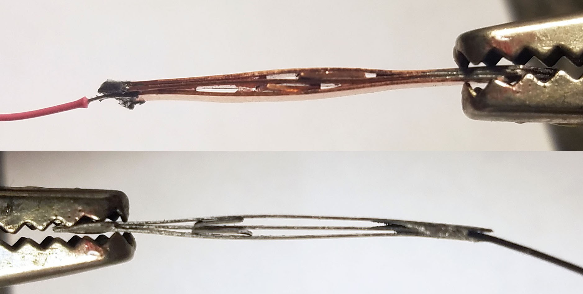
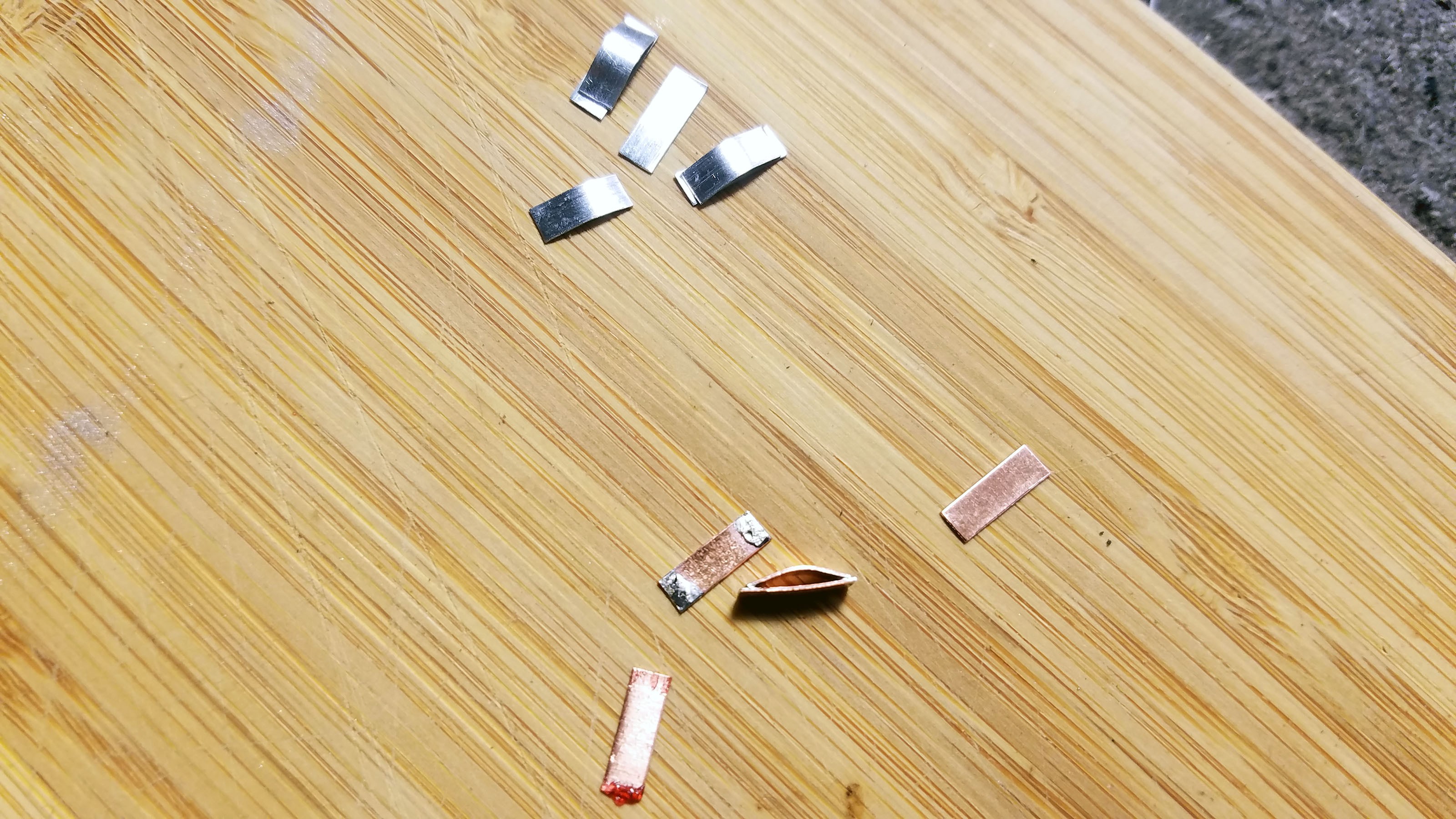
(Above) Magnesium-copper (Mg-Cu) galvanic cell encased in the smart pill enclosure immersed in a 0.16M hydrochloric acid (HCL) solution. The voltage across the cell when fully immersed is 1.29V (average over one minute).
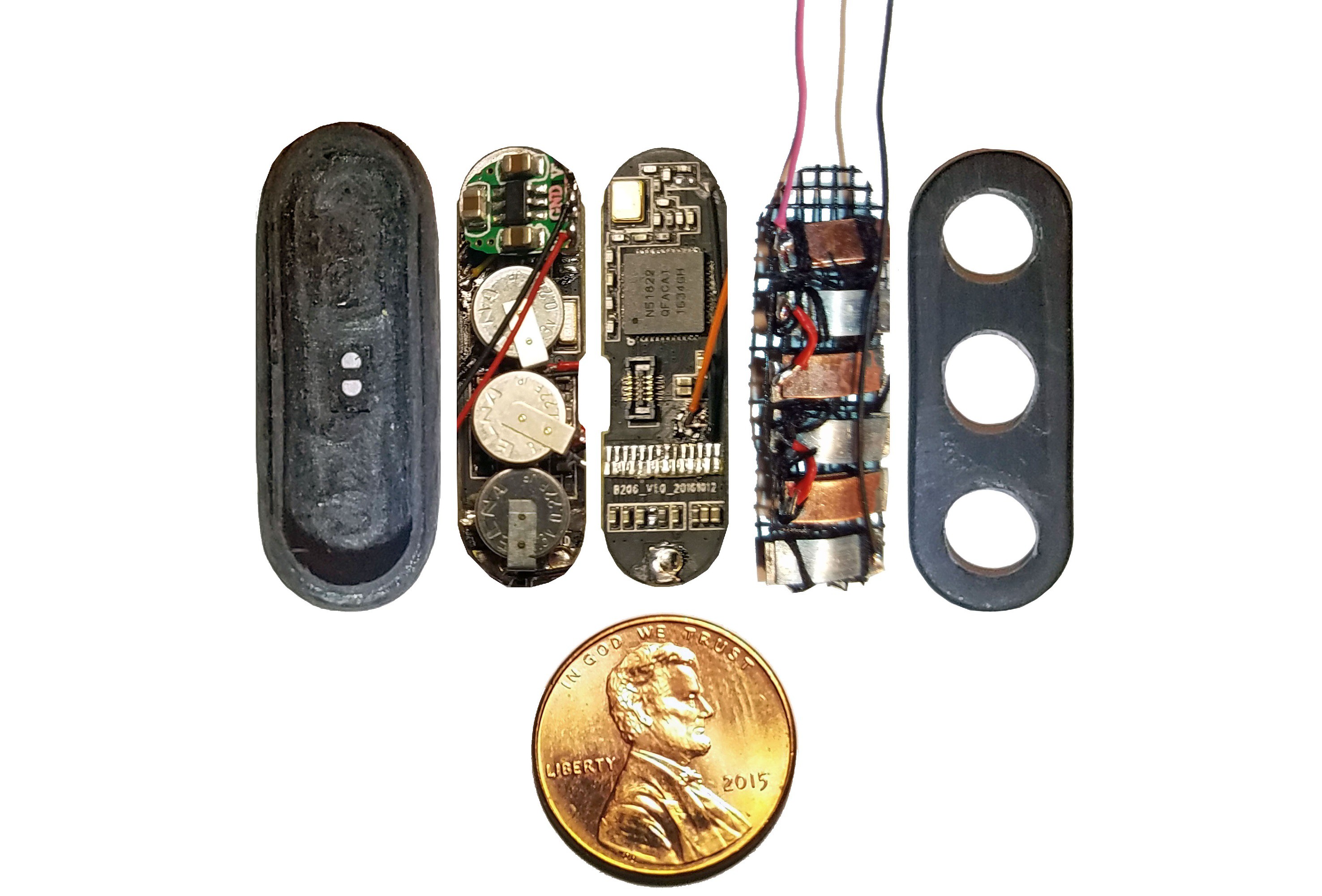
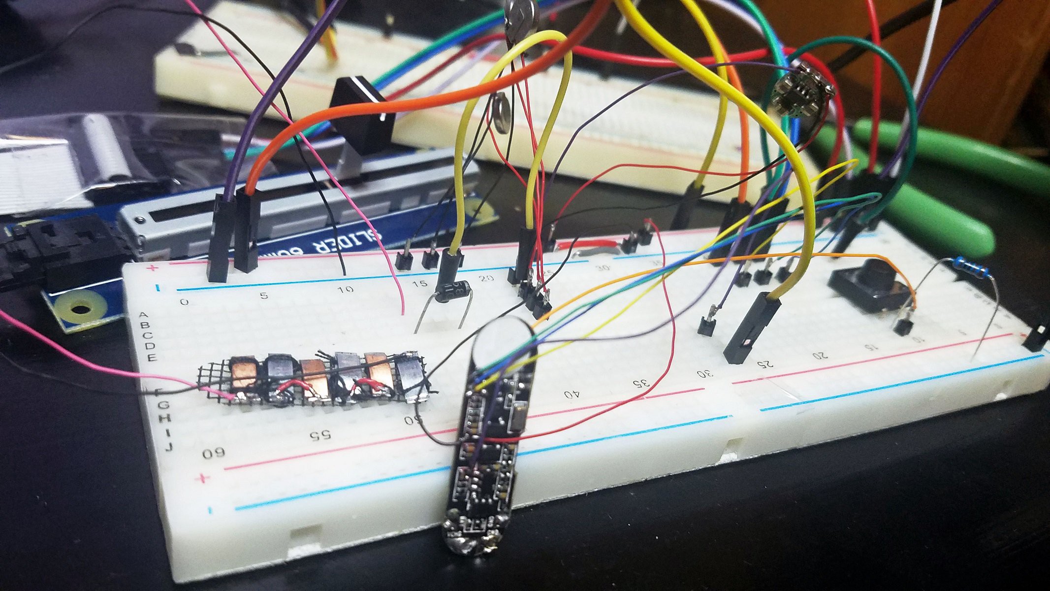
(Above) Components of smart pill sandwiched into injection molded plastic enclosure arrayed in ascending order left to right.
Far left: shaped and ground out activity tracker enclosure.
1st from left: three super capacitors in parallel, back charge protection diode, voltage boost converter, bottom view of activity tracker PCB.
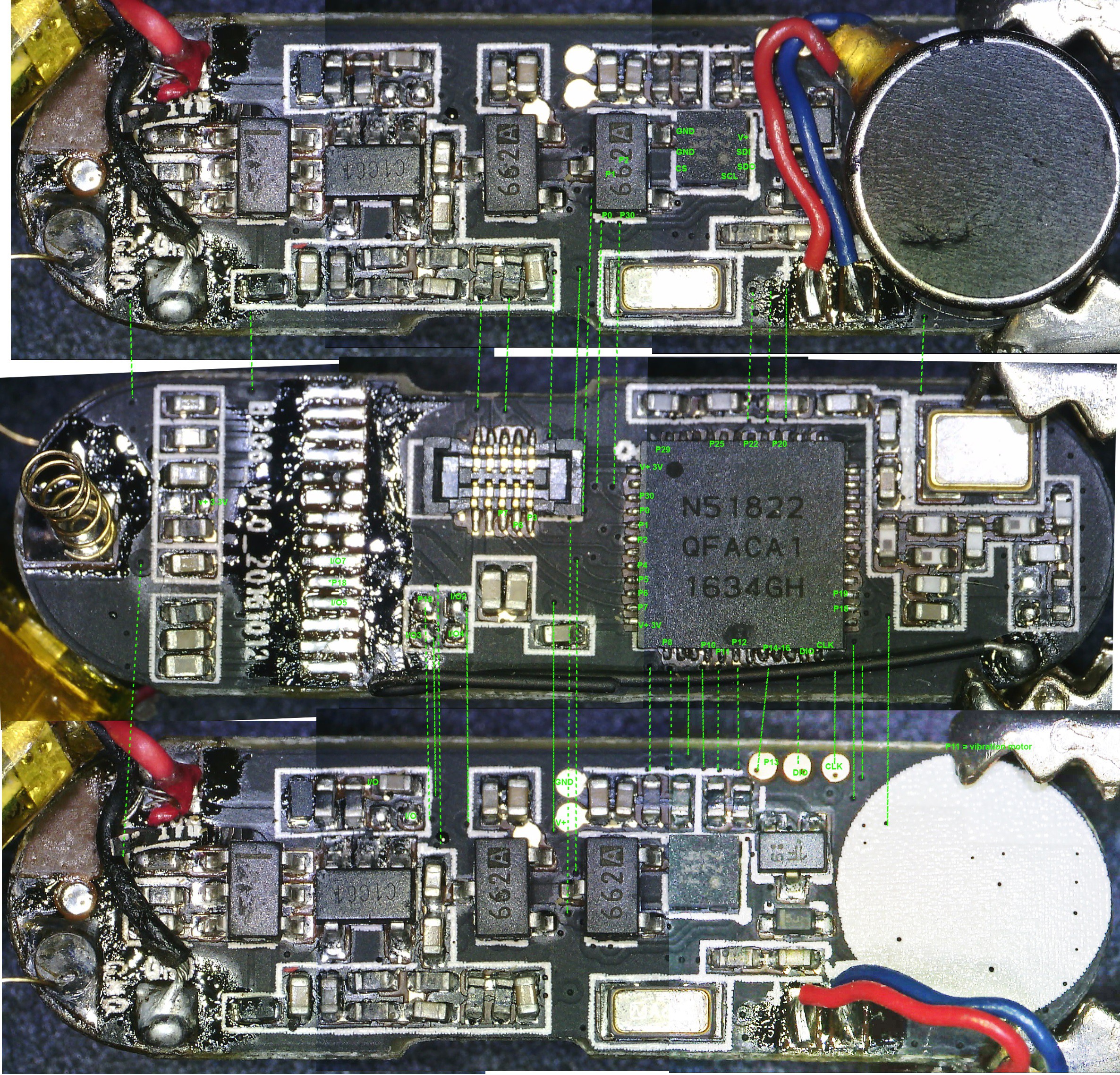
2nd from left: top view of activity tracker PCB including Nordic nRF51822 ARM Cortex-M0 SoC chip.
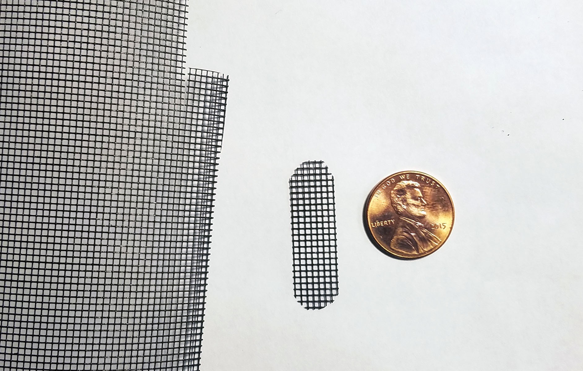
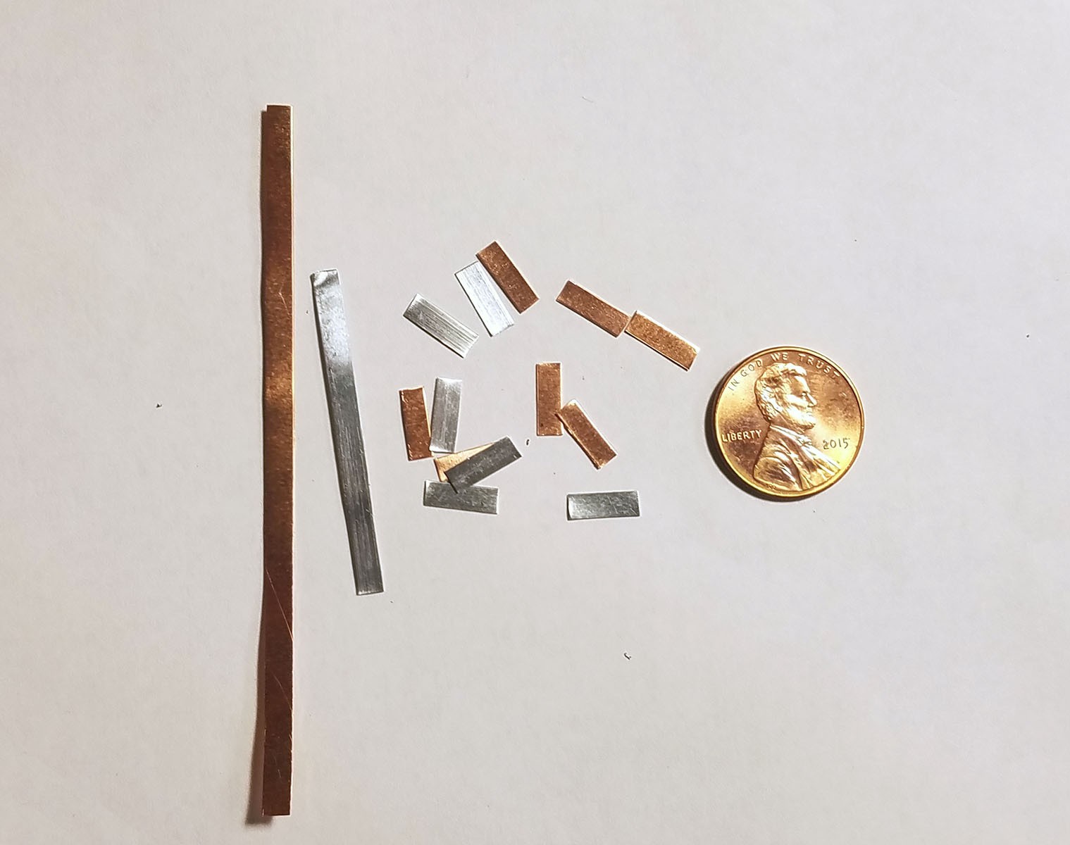
3rd from left: pile of three Zn-Cu Galvanic cells in series. The electrodes have been sewn down to a plastic mesh to keep them in place and allow free flow of electrolyte.
Far right: enclosure cap with holes for gastric fluid containing hydrochloric acid electrolyte to enter device. The enclosure will be filled with epoxy until everything but the galvanic cells are encased so gastric fluid entering the enclosure will not damage the electronics.
DESIGN
Build Steps
- The OLED display, battery and vibration motor of a small hackable activity tracker are removed and the enclosure is shaped with a Dremel to make it more pill-shaped and create extra space.
- Three pairs of Zn-Cu strips as long as the activity tracker circuit board is wide are created. These Zn-Cu strip pairs are layed in an alternating array - the array is as wide as the activity tracker is long. The Zn-Cu pairs are wired so that they form three galvanic cells in series. I sew all these strips down to a of plastic mesh the same size as the activity tracker PCB to keep them in place. *Note: currently undecided as to whether Mg-Cu or Zn-Cu is best. Going back and forth for now.
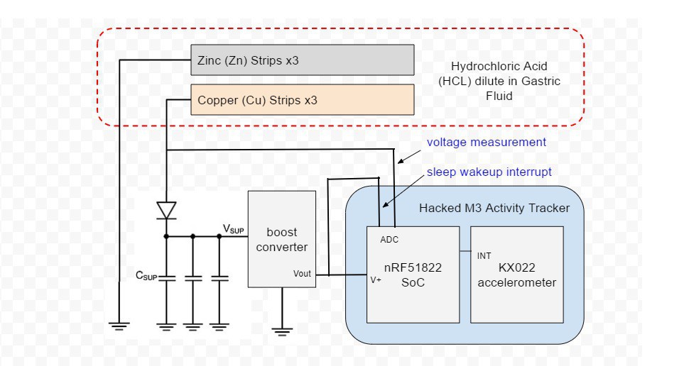
- The positive (copper) lead from the galvanic cell bank is connected to a Schottky diode and the negative (Magnesium) lead is connected to ground on the activity tracker PCB.
- Three tiny coin type 3.3v super capacitors are wired in parallel so that they form a capacitor bank. The positive leads from the capacitors are connected to the diode. The diode will prevent any back charge from the capacitors to the Zn-Cu strip galvanic cell which could cause...
 The completed array of galvanic cells is placed inside the enclosure to make sure everything fits and stays in place.


 Capt. Flatus O'Flaherty ☠
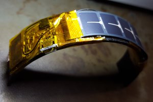
 DrYerzinia
 mikrotron
 Silícios Lab
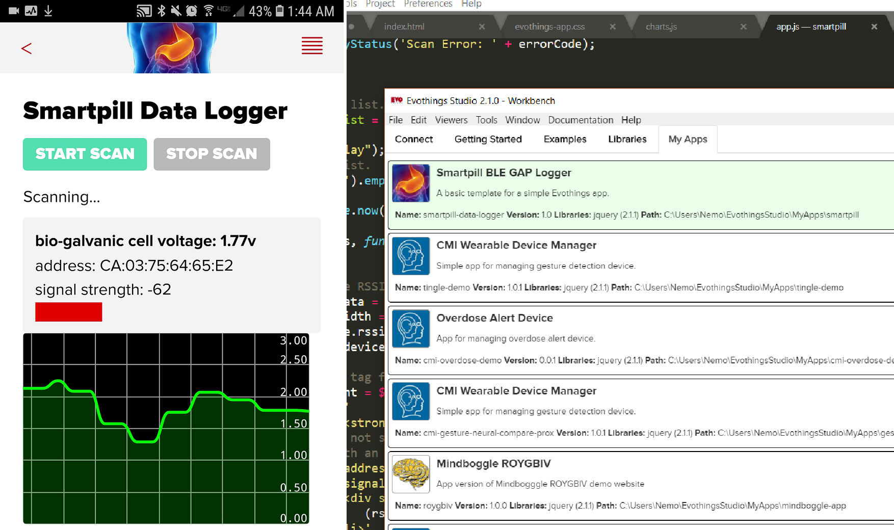
I'd really like to get this working with Bluetooth. Once of my prime objectives is to make medical device research conducted in expensive university labs more open and less expensive. The MIT team that did a similar experiment used a transmitter in the 900MHz range. I tried placing an activity tracker in a box lined with one inch thick gel/water ice packs (room temperature) and I was able to detect BLE GAP broadcasts + connect over BLE GATT. Granted 1" of mater/silicate gel isn't the same as the abdomen wall. Do you have any suggestions for making this work better using Bluetooth?