 AVR
AVRAbstract
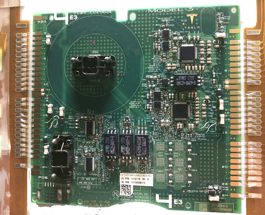
SolPak is a rechargeable portable battery pack that can be charged via solar panels or AC mains voltage. The pack uses 18650 lithium ion cells and will be using the ADI LTC6813HLWE-1#3ZZPBF battery balancer/monitor chip suspected to be used by Tesla in the model 3 pack. SolPak will have modular output modules where different DCDC converters or DCAC converters can be swapped in based on end application use. The pack is intended for portable powering of devices, off the grid solar power, portable solar for camping longterm, and custom EVs.
Detailed Description and Breakdown
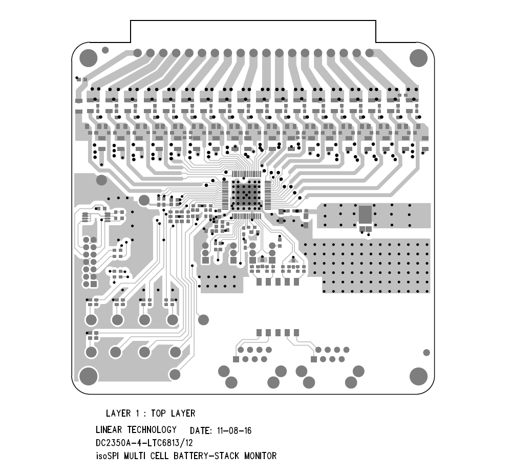
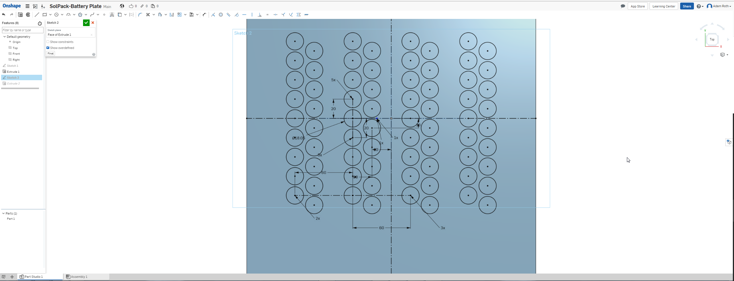
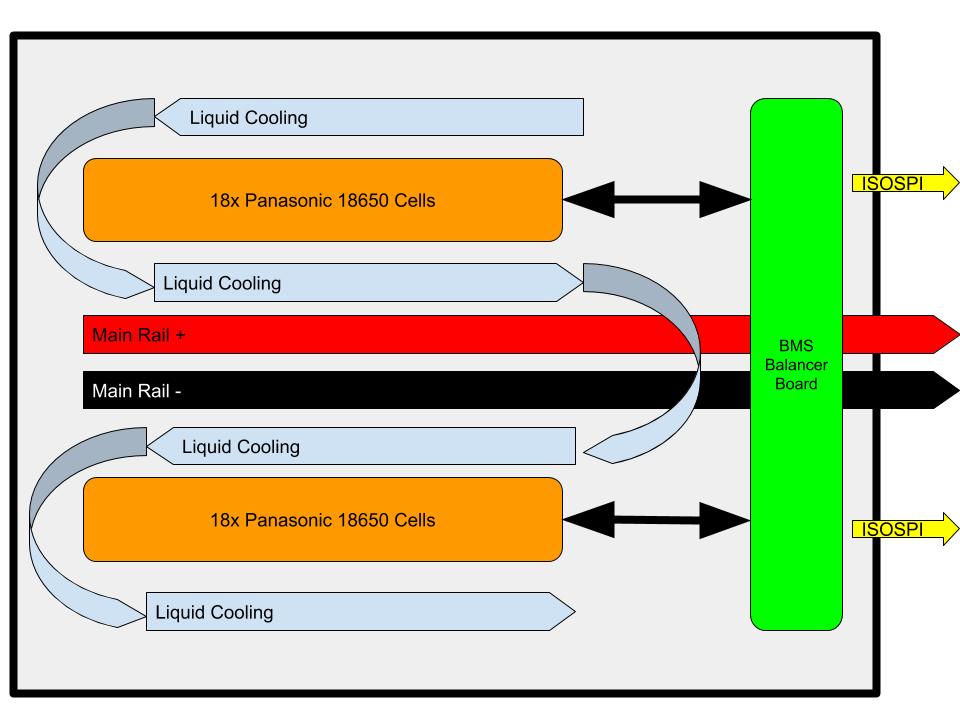
The battery banks will consist of 18 18650 lithium ion battery cells, there will be two banks in the first prototype. The battery balancer, monitor, and charge control board will consist of two LTC6813HLWE-1#3ZZPBF for monitoring and balancing each bank, the chips can interface with each other to balance all cells together. The cooling system will be integrated in with each battery bank. Right now I am planing copper tubing attacked to copper plate pressed against and between the cells to cool them as loads of current is drawn. The liquid in the copper pipe will be pumped through a radiator or some passive heat exchanger. In the event of a radiator there will be fans. I'm still developing a solution for the charge controller portion, be I'll have it ironed out in the week. The overall system control board will be based on a STM32 MCU, it will talk to the battery board and the converter module interface, it will run the main firmware that marries together all the subsystems. The swappable output converter module interface is meant to allow the user to choose the outoput voltage for the end application. Swap in a DCAC inverter for 120VAC power to run your laptop or xbox while camping. Swap in a DCDC converter to power your robot etc.
All this good stuff is going to be mounted in either a custom case made from carbon fiber sheet cut on a CNC with brush aluminum panels here and there or I'll get some off the shelf flight case and use that. What I really want to do is build a frame out of 2020 aluminum extrusion with carbon fiber panels on the sides and to mount everything to the carbon fiber panels, then plat the outside with bushed aluminum sheet. Have holes cut for the radiator and fans to breath.
General Specs
- 18650 cells two x18 banks
- LTC6813HLWE-1#3ZZPBF Battery balancer and monitor IC
- STM32 MCU for overall system controller
- Custom carbon fiber and brushed aluminum case
- Sealed battery compartment
- Module DCDC converter options, swap out/in converter for give voltage
- DC/AC inverter option
- Charge with solar panels or AC mains voltage
Energy Harvesting Challenge 2018:
In todays modern world there are many energy sources and storage methods available. The most design and powerful storage technologies are very expensive and controlled by patents. While there are many options for battery packs available there are not many open source solutions that have the same level of performance as the leading commercial solutions. SolPak is an attempt to build a open source battery pack that competes with the technology inside Tesla battery packs both home and car. There are many DIY powerwall and home battery storage projects online but SolPak will be using a custom BMS systemed based on the Tesla Model 3 battery pack.
SolPak addresses the energy harvesting problem from the storage side of things. There are many ways to generate electrical power, such as wind, solar, combustion, nuclear, and tidal. SolPak is none of those things though SolPak could hold the power generate by any one of them but I am choosing to focus on solar and mains voltage. Solar panels have come down in cost and have become more accessible, there are even ways to make DIY low cost panels, they also work...
Read more »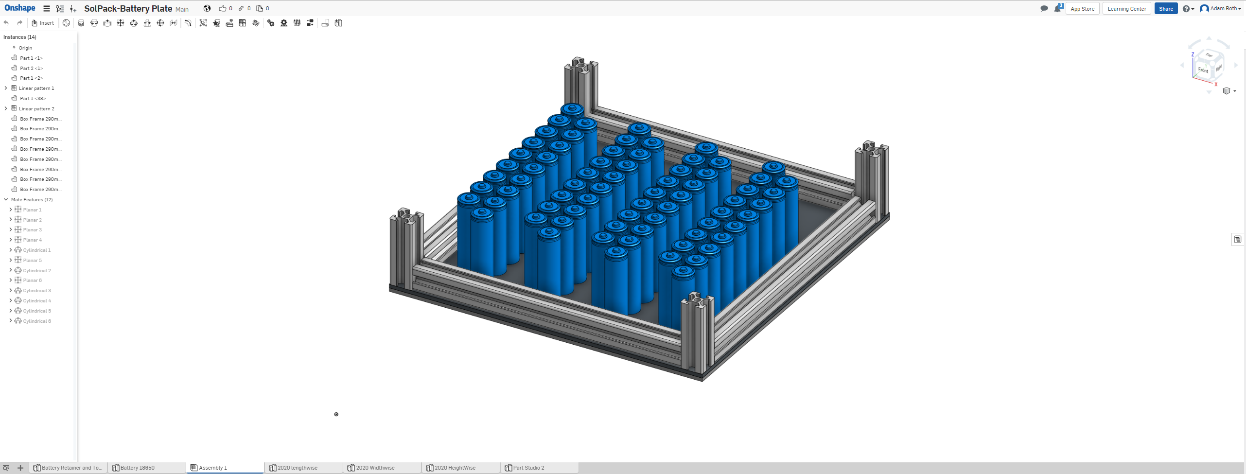


 AirCruiser
 Rory
Rory
 Hulk
Hulk
 Kumar, Abhishek
Could you use more standard battery terminology? What is in in terms of series and parallel? What's the target voltage and capacity of the whole module, what's the desired output parameters? A cell can be an individual 18650 or in the context of a larger battery a group of 18650s in parallel can be a cell.
18 18650s is fairly small for a cell. Most grid holders are for 20. That gives room for a U shaped bus bar and individual 18650 Tesla style cell fusing. It's highly advised as it can prevent a short from damaging the cell.
Individual cell balancing isn't complex. The simplest is a voltage reference, a pair of precision resistors as a divider, a comparator, mosfet, and power resistor. If the voltage goes over say 4v then it will bleed off energy until it's back to 4v. I say for 4v because charging to that level and cutting off at 3v greatly extends the cycle life of a li-ion 18650.
Li-ion isn't complex when it comes to management. It just tends to have a fiery temper when it's pushed past it's upper charge limit or is heated too much by over charging/discharging. The '18 Cells' is for 18S, 18 in a series. That's likely far more voltage than you want to deal with. If you want portable use stick with 24v with 7 cells in a series, or 12v with 4 cells in a series. The reason for the extra cell in series is the low voltage points. Most inverters will cut off with usable power in the cells if there are only 6S or 3S. For connectors Anderson PowerPoles are the standard if you target it at places where many different solutions are being used.