 ziggurat29
Summary
Some research was done into existing projects. It's still not clear if I should attempt my own twist on a mesh networking protocol intended for mosh pits.
I am setting up for experiments with the nRF24L01+ modules, and 'Blue Pill' STM32F103 boards.
Deets
I did some initial cursory research. As expected, simply doing a web search on 'nrf24l01 mesh' yielded many existing projects, libraries, and other sundry mish-mash of mesh. Some standouts:
Home Smart Mesh - Hackaday.io
https://hackaday.io/project/20388-home-smart-mesh
https://www.homesmartmesh.com/mesh/
This looks like a very high-quality project. Maybe it will obviate my doing any work, but I need to review it more. It seems to be oriented towards being able to deploy nodes in an ad-hoc manner around the house, and have a self-organizing mesh evolve from that. That's great! However it does also seem to be designed for more-or-less fixed placement of nodes, rather than rapidly moving (which is fine for it's design intent), so I should look to see if that is an issue. I'll probably have to build it and try it out to know for certain. Also, it seems to be designed for a reasonable number of node for a home mesh -- 255 max, which is too low for my application. Maybe that's adjustable somehow. Lastly, there are distinct roles that nodes play, with routers and non-routers. This is quite common in mesh networks, but I was hoping to have the various nodes be a strictly peer-to-peer implementation.
Still, it looks like a greate project, and I will have to kick the tires with the firmware, regardless if I wind up using it in this application.
RF24Mesh- Mesh Networking Layer for RF24 Radios
http://tmrh20.github.io/RF24Mesh/
This is a library/project specifically for nRF24L01+ devices. It looks pretty stable. It involves a 'node' for tracking address assignment, which doesn't fill my heart with joy. Also, there is a 255 node limit. Still, the code is worth a look, I think. There will be something to learn, I'm sure.
B.A.T.M.A.N. protocol concept
https://www.open-mesh.org/projects/open-mesh/wiki/BATMANConcept
While researching some general mesh routing topics, I came across an experimental protocol named B.A.T.M.A.N. Some things which caught my eye were the motivation to distribute the routing information in sub-graphs, rather than having a full topology graph stored anywhere. I think this sort of thing will be important for handling rapid local topology changes that are expected in the mosh pit.
This protocol is intended for use over IP and UDP, and talks about 'small packets' of 52 bytes, which is larger than the absolute maximum packet size of the nRF24L01+, so regardless of what it is, it will need some modification. Still, it seems worth further study.
In a more general sense, I came across several academic publications about current mesh routing algorithms, so I will need to familiarize myself with all of those, and their relative strengths and weaknesses. E.g.
https://pdfs.semanticscholar.org/f840/813413c48f7caf3c9e9b229e964ddfe3d77e.pdf
A Survey on Routing Algorithms and Routing Metrics for Wireless Mesh Networks
OK, coming out of the library with my eyes glazed over, I needed a little break with some hardware. Regardless of what I'm going to do, I still need to have a board with a radio on it for experiments.
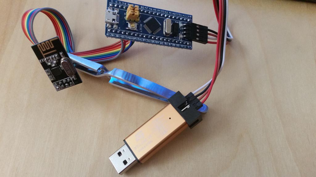
I did discover that I have 14 nRF24L01+ modules laying around. I've never used them before. I bought them on a whim thinking they might be useful someday, and I guess today was that day.
I need to have something to drive them, though. I have a pile of boards, but for this project I thought that I might use the "Blue Pill" STM32F103C8T6-based board. I have 4 of those on-hand. They don't have honking RAM/Flash, or particularly exotic peripherals, but since this is a research project focused on the networking, I think they will be well suited. If I can get the whole thing working in the 20 KiB RAM, then that will be 'good' relative to integrating the result into other projects of larger scale. (I don't know if I'll need 20 K -- maybe (hopefully) much less. However, these nodes will often have to function as the network's router, and that may impose larger working set sized requirements than a conventional TCP/IP client node. Maybe. We'll see.)
So, the first step, as usual, is creating a project. Fortunately, I had created a boilerplate 'BluePill' project for the STM32 CubeMX, so I start with that. I picked some pin assignments for the SPI to the radio, and a couple gpio for 'IRQ' and 'CE', and that's all I'm goign to hook to the module. I'll use USB CDC for any debug I/O to the board (when I get that far).
This also gave me an opportunity to finally try out the cheap Chinese ST-Link knock-off. It's really quite amazing. The radio is about USD$ 1, the microcontroller on board with connectors is about USD$ 2.50, and the ST-Link is about USD$ 3. Free shipping, lol. You just have to wait 4-6 weeks for delivery (an eternity now, but this was the standard expectation for everything in the 80's).
I configured the project, burned, and validated. So, now I have an initial testing node. I went ahead and ordered 10 more BluePills so that I can make at least a few nodes to play with.
- it is an st-link v2. NOT a v2.1. There is a subtle difference in a feature, and if you select 2.1, you will likely get confused by it's not working
- notice that the BluePill has 4 pins on the side for the SWD debugger port. In particular, it does not have reset (NRST). That pin does exist, it's on the edge, near the yellow jumpers, but you don't have to connect to that. What you do have to do is tell the dev tools to 'connect under software reset'. This means that there will be a SWD command sent to cause the processor to be in reset, rather than using the reset signal line.
The challenge is that the project, by default, will choose 'hardware reset', which will cause the dreaded 'failure in lauch sequence' message. (and this message means nothing; a zillion things can cause that, this is just one of them)
What you have to do is drill down into Debug Configuration..., then the Debug tab, then there is a button 'Show generator options' (the debug script file is dynamically generated). Click the button to show the goodies.
The goodie you need is under 'Mode Setup', 'Reset Mode'. Select 'Software system reset'.
Now it will use SWD commands to reset the board. - While you're in that dialog, on the 'Startup' tab, near the bottom is a checkbox 'Runtime Options' 'Set breakpoint at' main. I uncheck this. This simply always puts a breakpoint at the start of main, and I will do that explicitly if I want one there, thank you very much. Breakpoints are a precious resource on these chips. You get six max, and one is needed to facilitate single-stepping, so I don't want to waste one on 'main'.
OK, having gotten the board up and sanity checked the build system, now I need to test sending SPI to the radio, and hopefully making it do something interesting.
Next
Basic nRF24L01+ functionality testing.
Discussions
Become a Hackaday.io Member
Create an account to leave a comment. Already have an account? Log In.