0%
0%
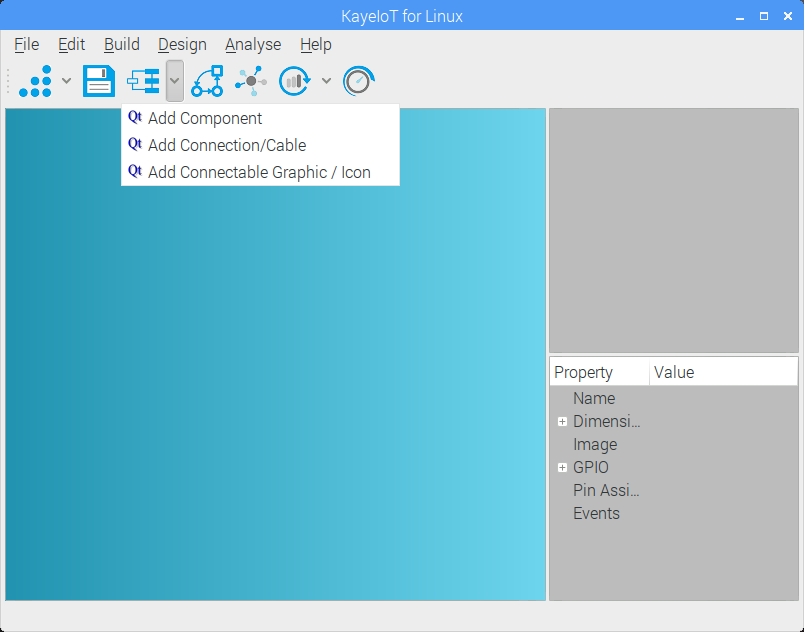
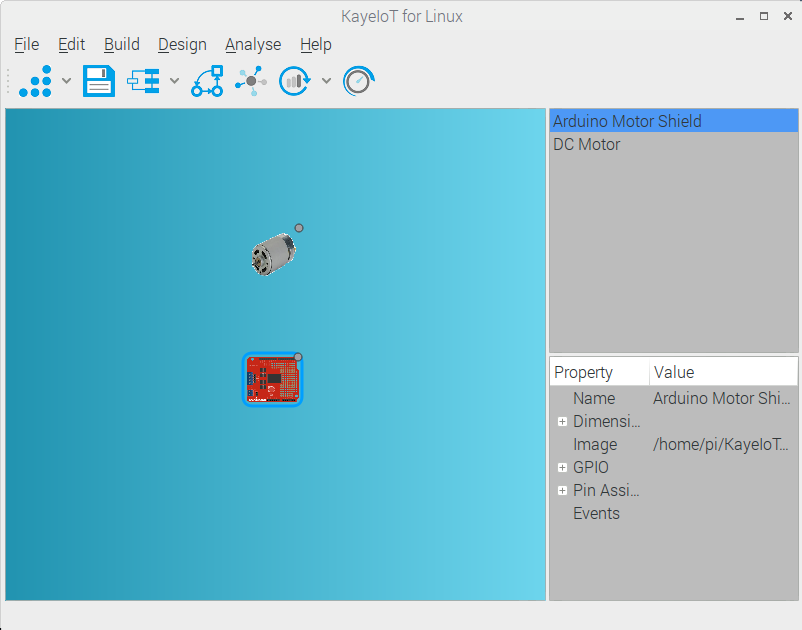
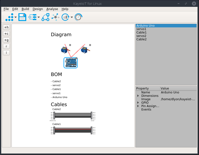
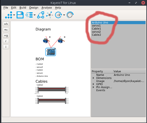
KayeIoT, CAD for Hacking and IoT
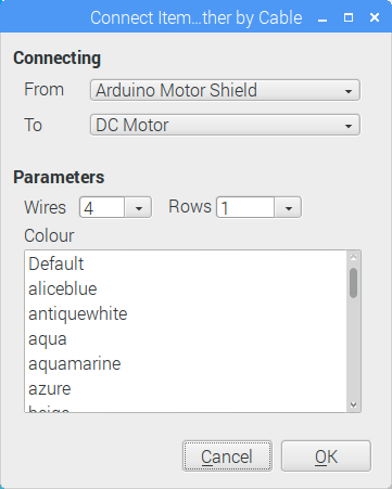
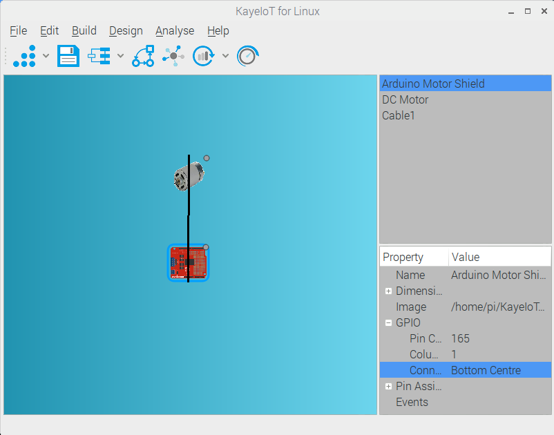
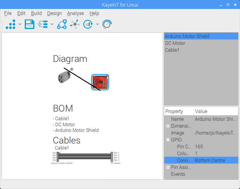
KayeIoT is a a Computer Aided Design for Hacking and IoT. It's a Cable Level Design Program for Projects that uses existing parts.
 David Lyon
Become a Hackaday.io member
Already have an account? Log in.
Just one more thing
To make the experience fit your profile, pick a username and tell us what interests you.
Pick an awesome username
hackaday.io/
Your profile's URL: hackaday.io/username. Max 25 alphanumeric characters.
Pick a few interests
Projects that share your interests
People that share your interests

 Oscar Gonzalez
 Patchr
 doctek