 Josh Cole
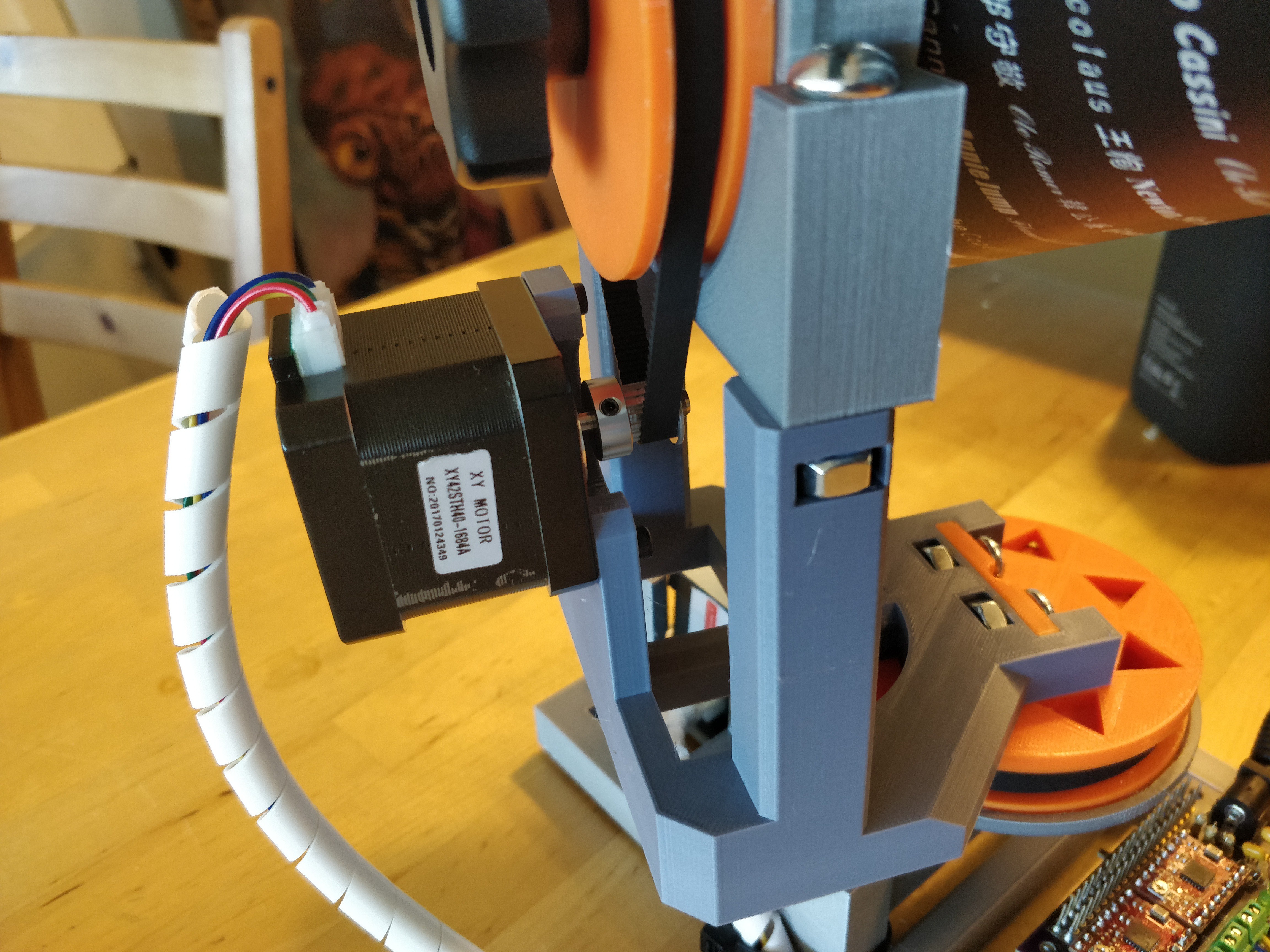
Pisolaris is a 3d printed telescope platform designed specifically for the Celestron "First Scope" http://a.co/4xyHqx0
Although I have not released the STL files, I am planning on doing so in the near future once my iterations become more stable.
In addition to making a motorized telescope base, I also wanted to write my own star finding software... which I have done, in theory :) You can find the math library I made on this github page: https://github.com/pisolaris/astro-math
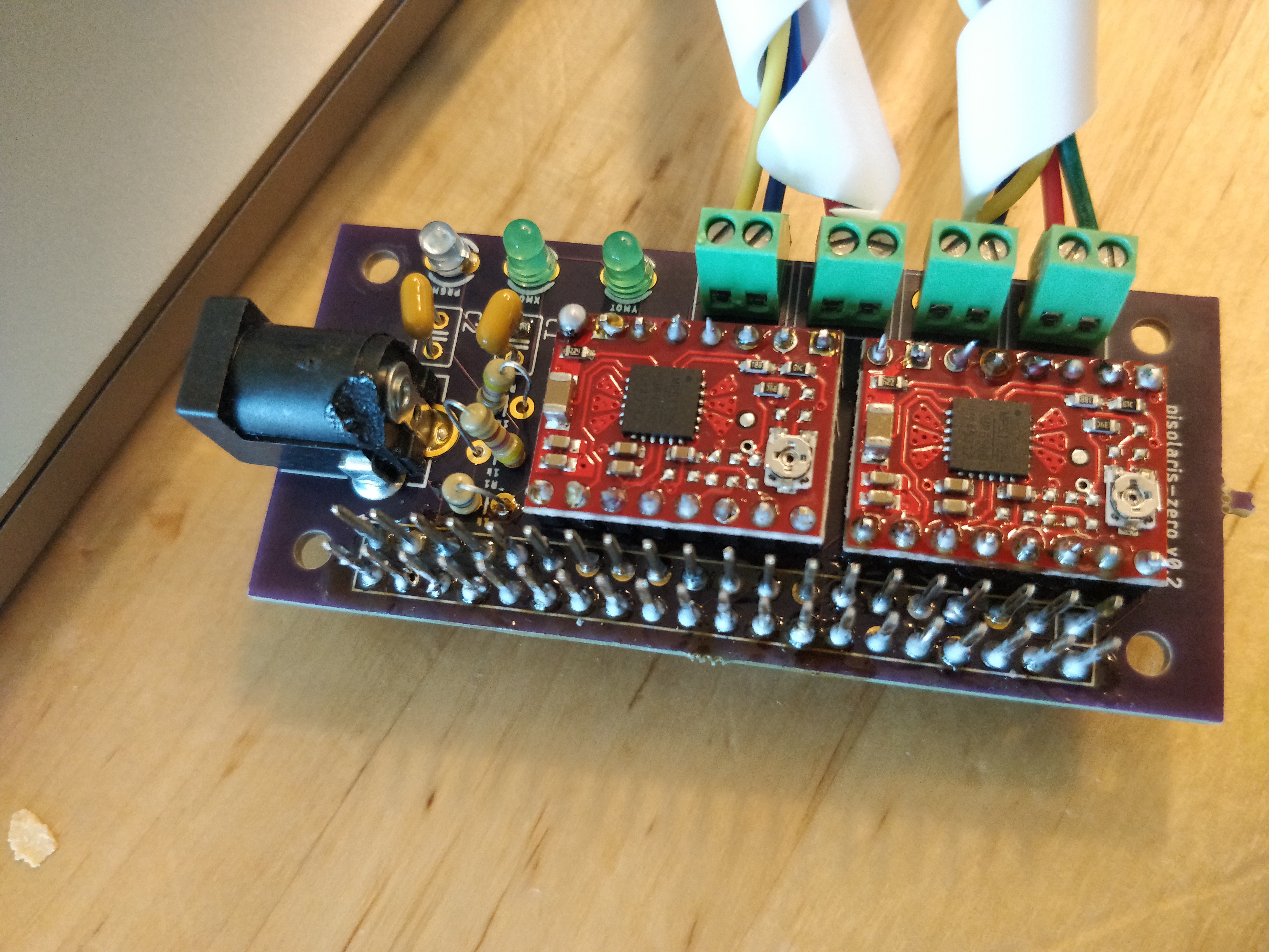
The general concept for star finding is to first develop firmware which can accept destination angles and translate those into motor steps. Then develop the software which can take the current time + gps coordinates + target celestial body and translate that information into angles for the firmware.
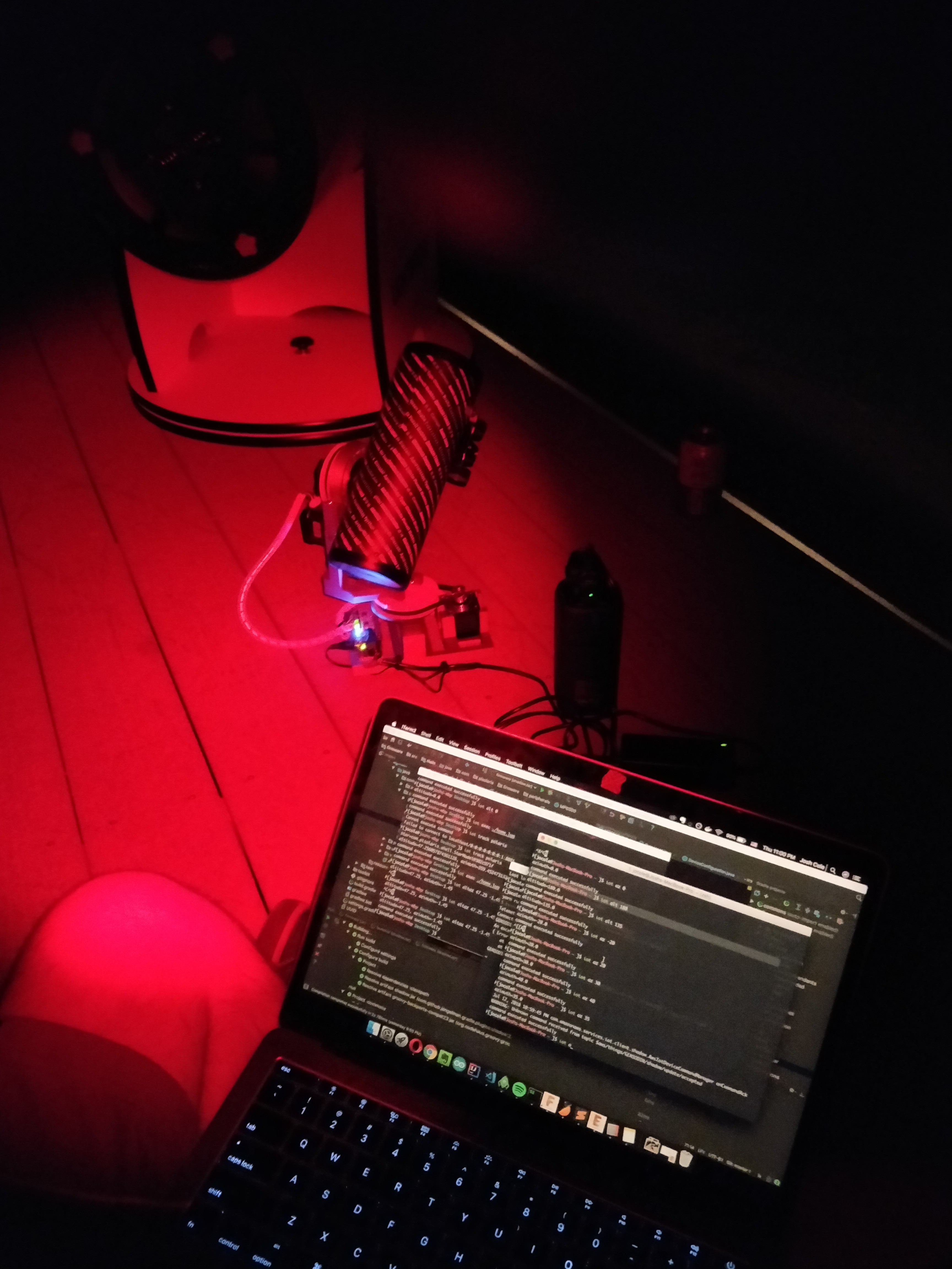
At this time, my firmware is not public because it uses AWS IoT and I do not have a good way to provision new telescopes with the current software stack. Making a version of the firmware easily accessible is on my to-do list though.
Stay tuned as I plan to release files soon! I'm nearing a stable iteration which should be good enough to begin sharing complete build instructions :)


 George Albercook
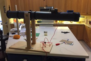
 Nathan Brown
Hi @manta103g
My firmware will (very soon, once I fix a bug) accept angles for both motors. This means I can tell it to do things like "rotate to 145 degrees vertically" or "90 degrees horizontally" etc. Because I use stepper motors and then add a further gearing mechanism on top of it, I am expecting reasonable positional accuracy.
With this kind of input, tracking celestial bodies should be doable. I wrote a math library (https://github.com/pisolaris/astro-math) which is based on polar coordinates. It can convert "right ascension" and "declination" into "altitude" and "azimuth" coordinates. If you go outside and face north, then look straight up at the sky, your altitude will be 90 degrees and your azimuth will be 0 degrees. So from that "home" position, you can navigate to any destination that is in the field of view.
There is another repo I discovered which has many many celestial objects encoded in the polar coordinates. https://github.com/astronexus/HYG-Database
Using the math library I made, the thought is that I should be able to convert any one of these objects into local altitude/azimuth coordinates at any given moment in time.
It's all very confusing though. The best resource I found which explains this stuff was actually a book (Astronomical Algorithms) http://a.co/7N6ckqf
I hope this helps at least a little :) I'm not entirely sure what would be involved in tracking the sun, but I imagine it's similar conceptually.