Close
0%
0%

Digital White Cane

The Digital White Cane can prevent frequent head injuries and provide intuitive navigation assistance for the blind and visually impaired.

Similar projects worth following
The Digital White Cane empowers people who are blind or visually impaired to live a more independent lifestyle. Using a discreet array of distance sensors arranged on an elastic band and worn across the forehead, it can detect objects within 2m (6ft). These measurements are converted to haptic feedback.

With minimal training, a blind person can develop a very natural sense of their surroundings. Using the Digital White Cane, they literally feel the space around them. Walking in an unfamiliar place is now dramatically more comfortable and enjoyable. With a new found confidence, getting from Point A to Point B is a safe and calm experience.

Problem: People who are blind and visually impaired face a huge number of mobility related head injuries.

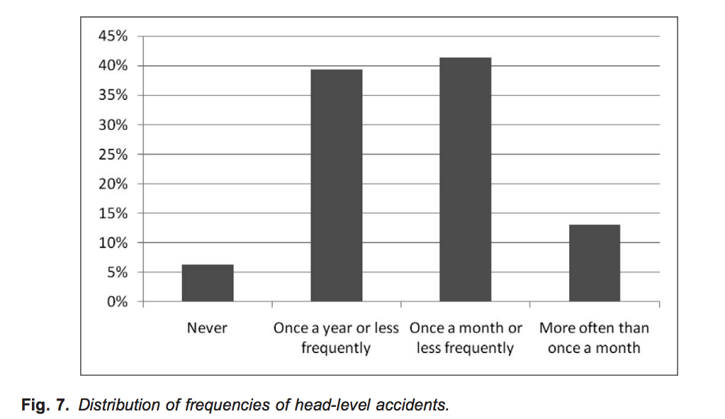
Source: https://pdfs.semanticscholar.org/609b/3d62282eaa5c2e4a89c803c0b401a789e27d.pdf

Other Methods 

Physical canes and sonar devices are useful, but provide limited information.  Both are only measuring one point at a time.

A camera has multiple points and provides lots of informations, but unless you have stereo vision, the multiple points still do not measure depth. Without stereo vision, a pillar directly in front of you would be indistinguishable from a distance skyscraper.

Our Device

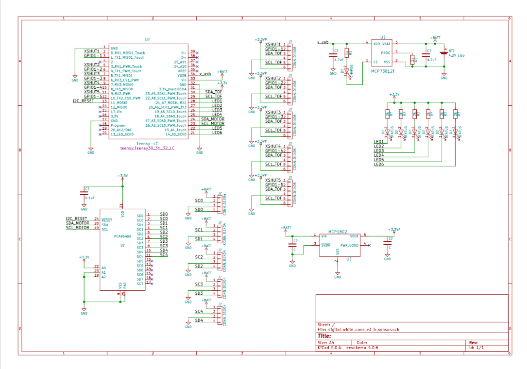
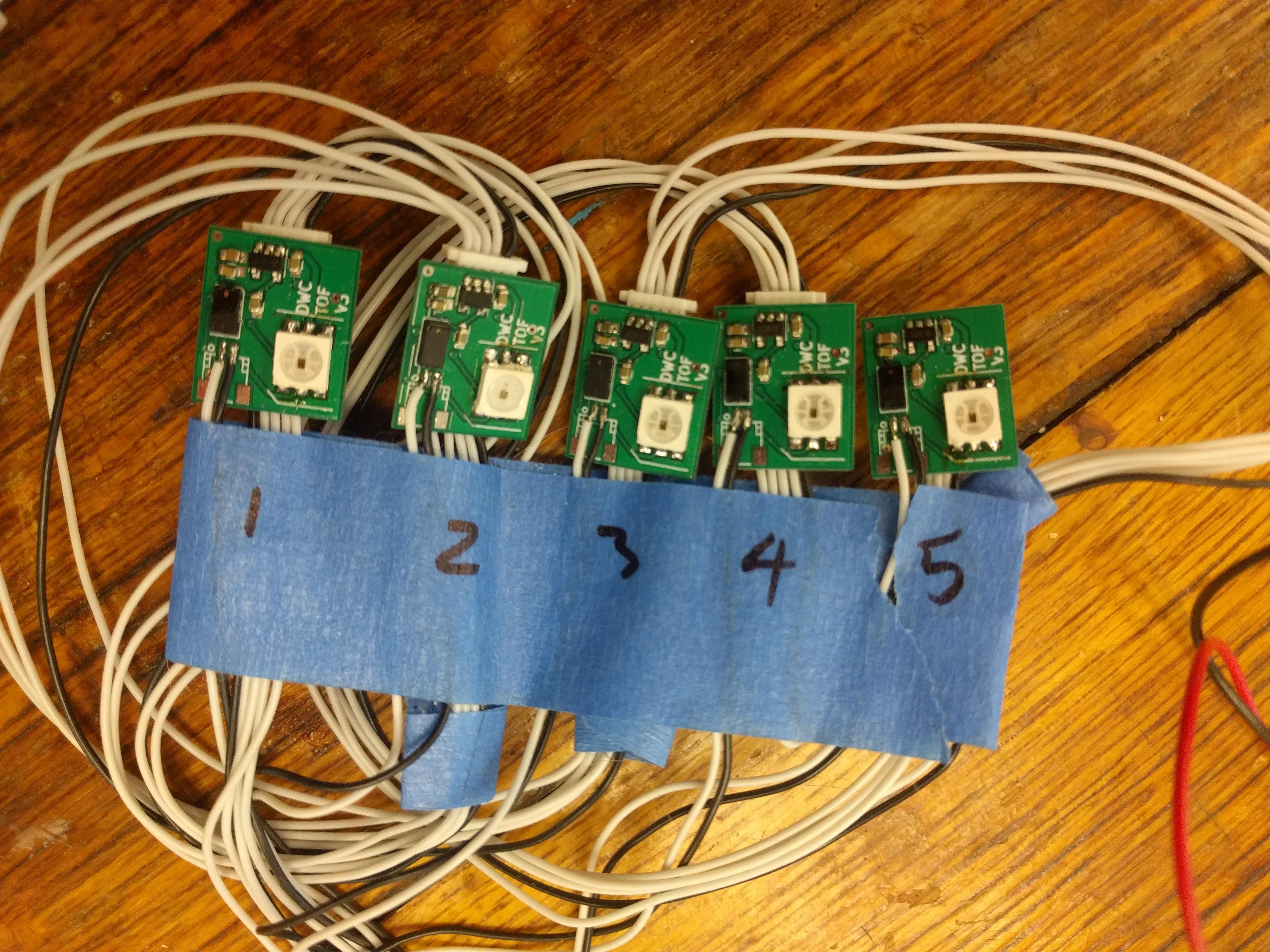
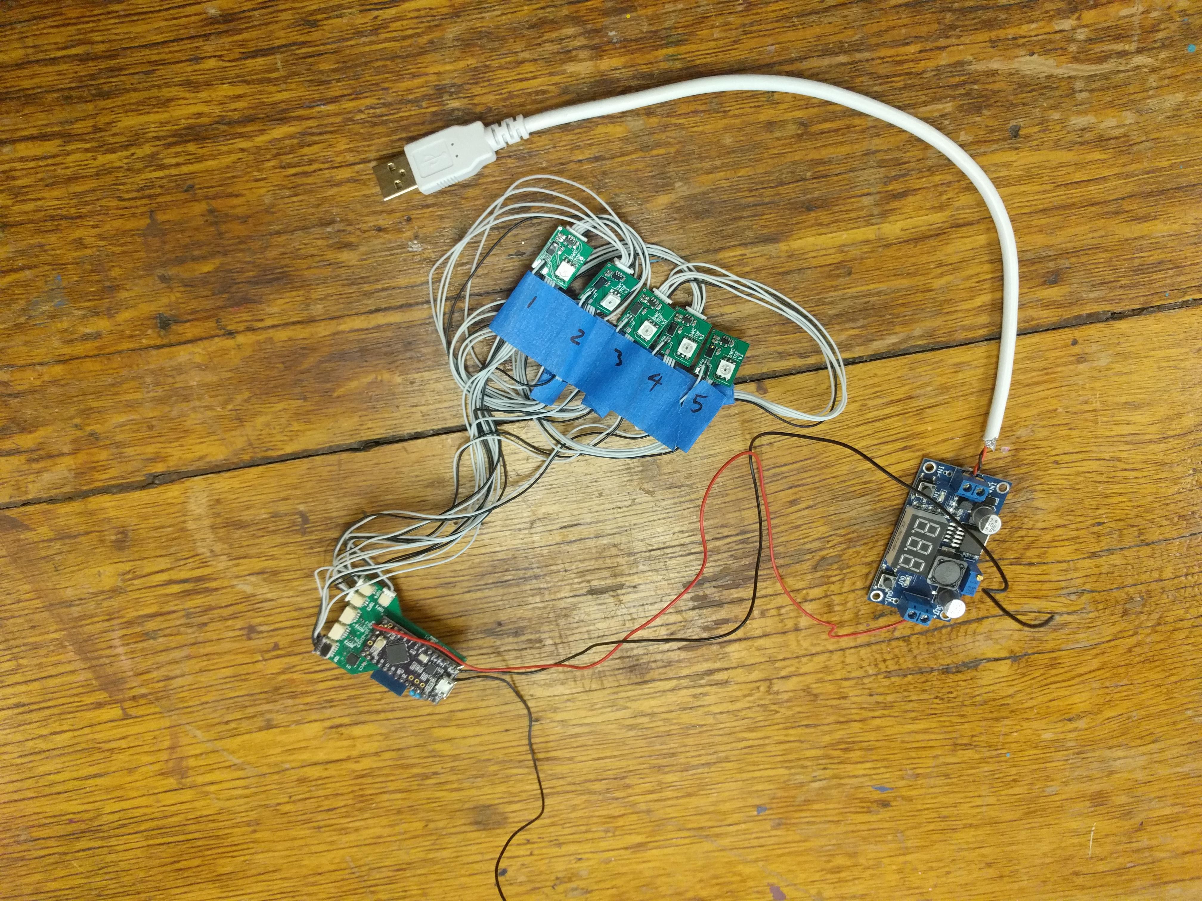
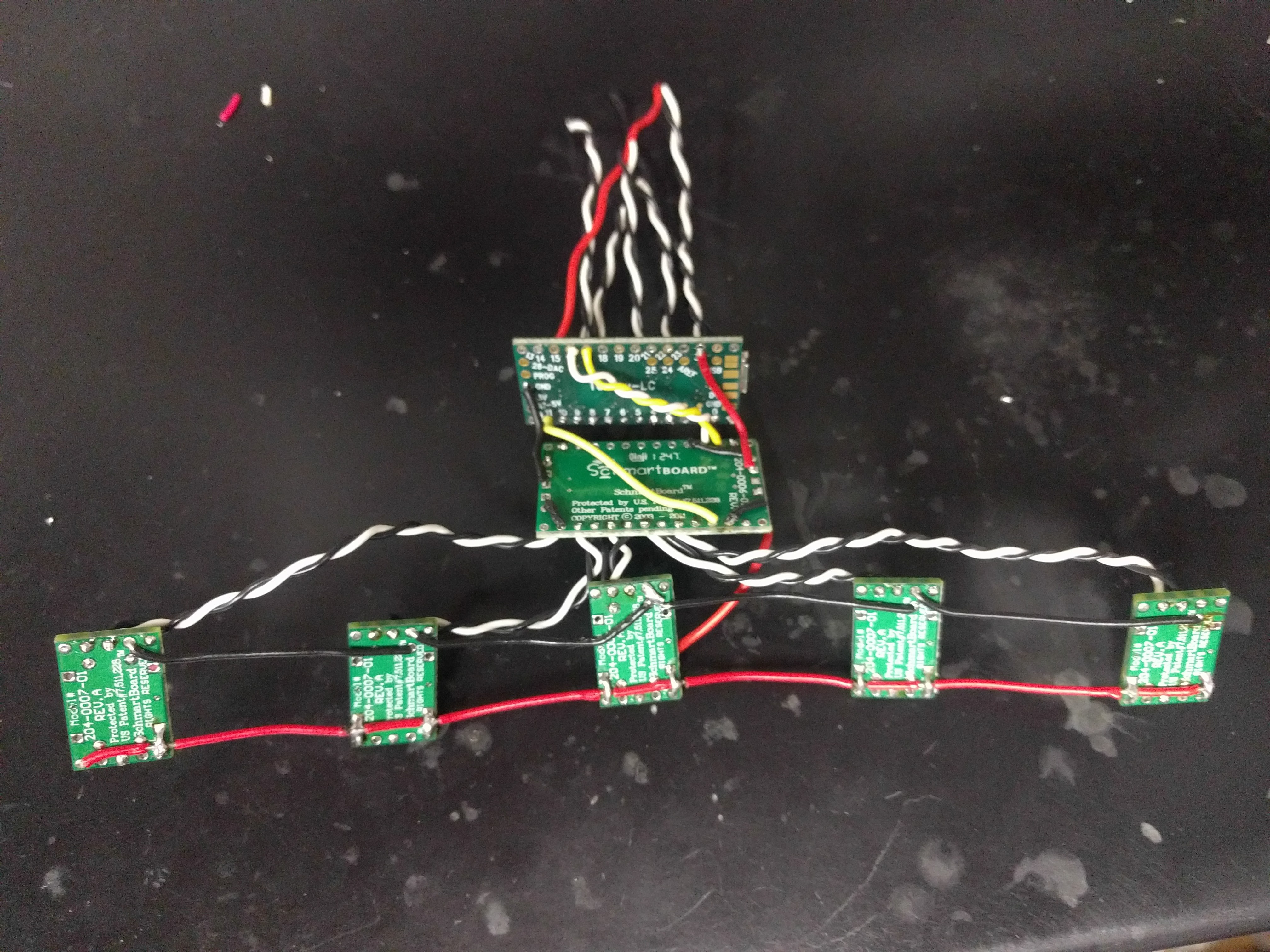
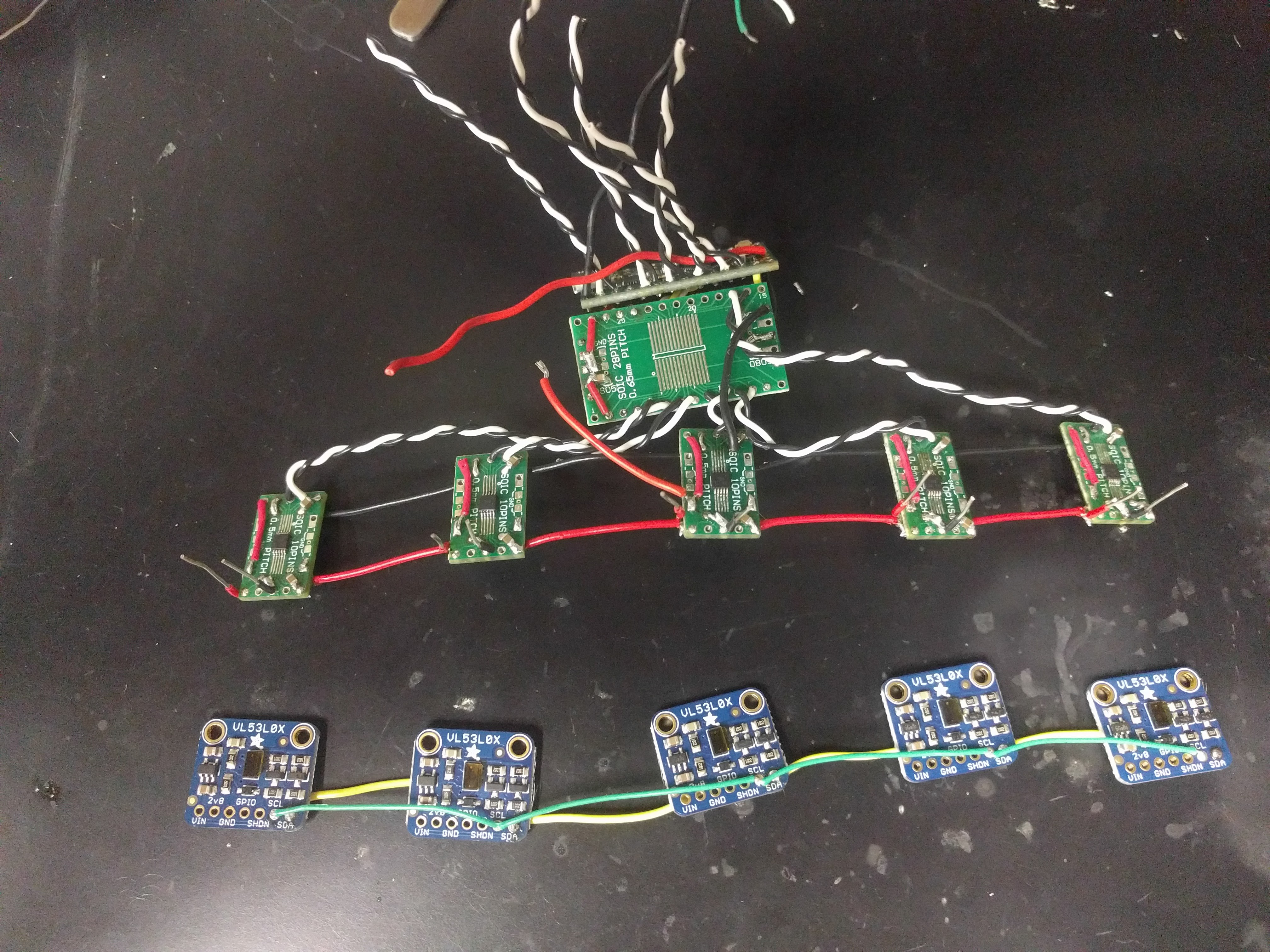
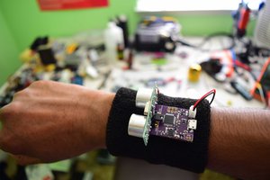
The Digital White Cane delivers immediate data and depth from multiple directions simultaneously.  This technology wasn’t possible before ToF LIDAR tech.  In the past, LIDAR was as big as a truck and very expensive.  We’ve created a lightweight and effective solution.

Cost

As 87% of the world’s blind live in developing countries (ref below), we endeavored to make a device that was inexpensive and easy to replicate.  When produced on a mass scale, our device is projected to cost less than $30 for materials and assembly.

R. Velázquez, Wearable Assistive Devices for the Blind. Chapter 17 in A. Lay-Ekuakille & S.C.

Mukhopadhyay (Eds.), Wearable and Autonomous Biomedical Devices and Systems for Smart Environment: Issues and Characterization, LNEE 75, Springer, pp 331-349, 2010.

Our First Real Life Test with Mary

Big Changes for Our Latest Device


Portable Network Graphics (PNG) - 363.56 kB - 10/21/2017 at 12:16

Preview
Download

Zip Archive - 835.63 kB - 10/21/2017 at 12:16

Download

Portable Network Graphics (PNG) - 373.29 kB - 10/21/2017 at 12:16

Preview
Download

Adobe Portable Document Format - 69.55 kB - 10/21/2017 at 12:16

Preview
Download

sch - 28.51 kB - 10/21/2017 at 12:16

Download

View all 15 files

  • 10 × Distance sensor The Sharp IR distance sensor
  • 2 × Teensy LC An Arduino Clone
  • 10 × Motor Driver ICs chips specifically designed to drive EMR (eccentric rotating mass) motors.
  • 10 × Pager motors

  • First of the new boards assembled

    George Albercook08/27/2018 at 02:19 0 comments

  • New thinking on haptic actuators

    George Albercook08/26/2018 at 22:12 0 comments

    It has been very difficult to utilize the very noticeable feeling when one touches or holds an actuator.   It may be that the sensation the one can feel when reaching out to touch an actuator it from a different type of receptor.  There are 4 types of mechanoreceptors on our skin. The Meissner's corpuscles respond to light touch in the 10 -50 Hz range while Lamellar corpuscles respond to faster changes in the 250 Hz range.  Actuators are optimized for the 250 Hz range.  

    It is also interesting to learn how the body responds to multiple points of touch.  If the points are close enough the skin can't distinguish them but that was not the interesting thing to me.  If one point of contact is within the region of a particular receptors and a second point is in the adjacent receptor's region of response the signal sent indicates the union of the two regions. 

    I think this may allow the skin to have a larger dynamic range. I could not find an answer in the literature (didn't look that long) but it makes sense to me that if many regions are stimulated the the detection limit of sensation would go down.  This leads me to try a different approach.  Maybe large pads of flexible points will allow for the detection of smaller signals.  We could divide the forehead into five segments each one with an actuator.  When the actuator vibrates ever so slightly the entire section of the forehead would feel it. This may allow for finer distinction in levels and allow for better depth perception.

    Maybe they could be made out of something like this thing made to hold a bar of soap.

  • v3.5 PCBs have arrived

    Nicholas Ristow01/19/2018 at 18:49 0 comments

    Recieved the first batch of PCB's for the prototype. It still uses the teensyLC, and adds a connector for a ESP8216-01 with its own linear regulator for remote telemetry. It plugs in from the back of the board.

    The main board also supports the i2c mux and lipo charging circuit to charge the LiPO from USB.

    The TOF sensor board also has a RGB addressable LED for use during testing.

    There is also a motor controller board.

    All of these bards have JST connector footprints, which we may or may not use.

  • Linear Resonant Actuator tests

    George Albercook10/21/2017 at 01:25 0 comments

    They definitely start and stop quickly and it seems that you can get a more varied output but there is still a problem. It took awhile to figure out how to even explain it.  They the actuators we're on the table it was clear that the amplitude was changing with the distance to objects and when you touched the actuators you could feel the difference but when you put the device on your head they felt less lively for lack of a better term. It looks like there are two things going on here. Apparently, the driver chip has a calibration mode which we have not used yet. The documentation says they will not work comparably and properly until they are calibrated. 


    But we expect that there is another issue.  We noticed that when you reach out to touch an actuator if you press too hard you stop it from moving very much and if you touch too lightly you can't feel it move.  People appear to automatically adjust their touch pressure to maximize the movement of the actuator. Everyone seems to do it and they do it almost instantly. 

    Unfortunately, when the devices are strapped to your head there is no self-adjusting. We tried mounting them on foam, in foam Wells so they could move freely, stuck to the headband or stick to your head. Many of these methods worked well enough but compared to the auto-calibration that people do with their fingers they are not performing as well as they could.

    So our next idea is to mount each LRA on a plastic strip and adjust the length and width be of the strip until it resonates at the same frequency as the LRA. That is about 240Hz. This will give us a reproducibly secure mounting method that interferes with the actuator as little as possible. Then we can adjust how hard the actuator rests against the forehead and try different touching surfaces and shapes. Maybe a cone-shaped piece of foam that only touches at the point at low amplitude and touches a larger area at high amplitude. We will have to test and see.

    Either way ERM or LRA the system works we are just optimizing now.

  • Linear Resonant Actuators

    George Albercook10/21/2017 at 01:06 1 comment

    There are two main haptic feedback technologies. Eccentric Rotating Mass (ERM) and Resonant Linear Actuators (RLA). Fancy terms for pager motors and speaker coils. Well it is not exactly that simple. The RLA have a frequency that the prefer to work at while speaker coils are designed to work at a wide range of frequencies. 

    We started with ERM actuators. They wabble around in a little circle as the motor tries to spin the off center weight. They are cheap but they are hard to control precisely. At low power the motors don't want to start so it is hard to get a large range of intensities out or them. They also take time to change power levels and tend to get warm at high power.

    So we wanted to try LRA which oscillate up and down like they are bouncing. They start, stop and change amplitude quicker than the ERM devices do and they don't heat up. So we bought some.

  • Final Step

    George Albercook09/04/2017 at 13:55 0 comments

    We have the multiplexer working properly.  In the test below it is addressing each individual motor in turn and making them twitch.

  • Head Mounted Version

    George Albercook09/04/2017 at 04:17 0 comments

    We made a lot of progress on a totally head mounted version. While these Sharp IR distance sensors were easy to work with and we had them on hand, there is better technology available.  

    In the past few years, the technology to measure how fast light travels  (the Time of Flight, ToF)  distancesas short as 1 millimeter to as long as 2 meters has become available in a tiny package.  

    Considering that light travels the length of a standard piece of notebook paper in one cycle of a gigahertz clock, that is kind of amazing. This technology is a form of LIDAR (Light Detection and Ranging). Think radar with lasers.  

    The photo below shows five breakout boards from Adafruit each with a VL53L0X ToF sensor made be  ST.


    Five tiny prototyping boards from Schmartboard with the DRV2606L motor drivers. 


    The motor driver boards attached to another Schmartboard holding an I2C multiplexer which is, in turn, connected to an Teensy LC.

    Both parts ready to be connected together.


  • Goodbye, Electric Dreads!

    George Albercook09/04/2017 at 02:24 0 comments

    Clearly the prototype was awkward to put on and take off.  Luckily, there is nothing about the concept that requires it to keep the original configuration.  

    The very first prototype used ace bandages to hold the pager motors in place on the forearms.  We chose the forearms because the skin in relatively thin and the nerve endings are numerous and close together. Plus, the area is not "used" for much else.  

    We tried several configurations and types of fabric to make a comfortable sleeve-like configuration.

    Here we tried stitching them into an elastic material. 

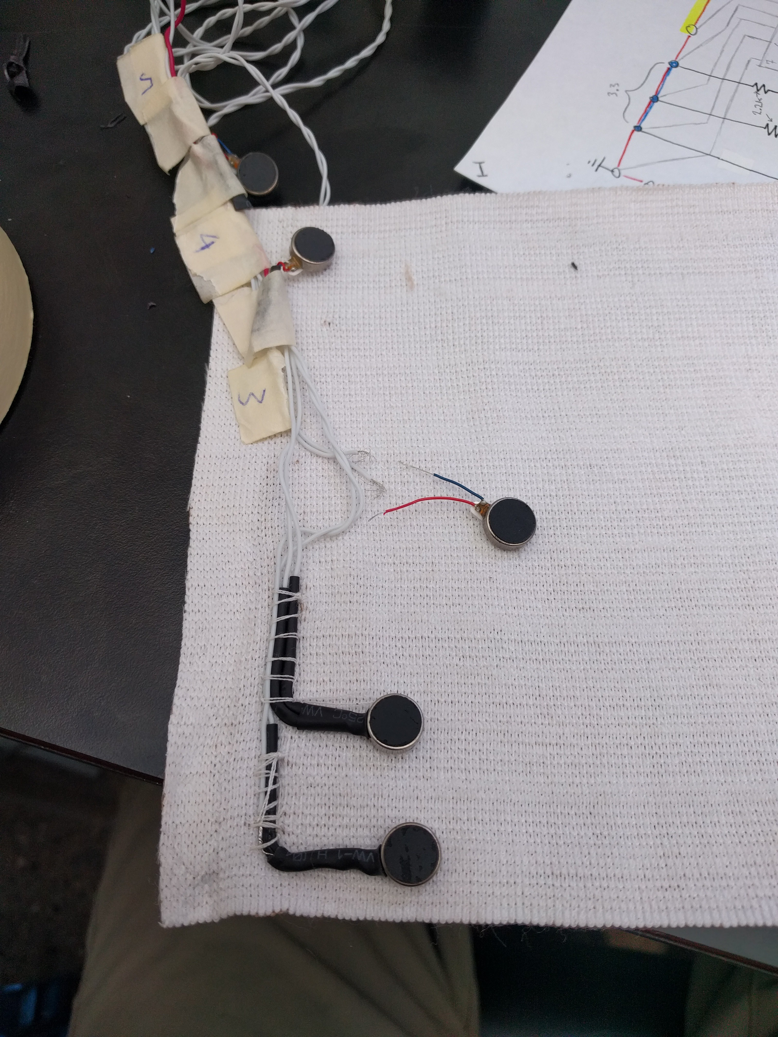
    This turned out to be awkward to put on. When putting on a shirt, it's surprising how much it helps that the sleeves are connected to the rest of the shirt.  It's similar to fastening your own bracelet.  One arm is less usable.

    Time for a new approach. We're going to put the whole thing in a headband.

  • Working with Haptic Signals

    George Albercook09/04/2017 at 01:56 0 comments

    After the rush of the Hackathon, we wanted to take a closer look at the fancy motor driver chips, which are made by Texas Instruments. 

    You might ask why not stick with the simple transistors that are working? The answer has to do with the physics of the ERM (Eccentric Rotating Mass) vibrating motors.  They have stiction. 

    When they first start moving it takes more power to start them than to keep them going.  This makes it very difficult to make them vibrate even a little. They also take time to get up to speed so it is difficult to get sharp transitions between levels. Thankfully, the DRV2605L chip addresses both of these problems and more. 

    The "L" suffix at the end of the part number indicates that it has a built-in library of vibration patterns. The library adjusts the power going into the ERM over time, resulting in refined vibration patterns. For example, it can overdrive the ERM for a short time to force it up to speed faster.

    We are still having some problems getting the DRV2605L chips to work.  At one point, we put one on the scope and it was clearly acting like it was trying to drive a huge capacitance.


    Several of the driver boards also had problems with drawing too much current.  We'll have to go through them carefully. Not at all unreasonable, considering we were working off of very little sleep and the pins of these things are half a millimeter wide. The soldering had to be done under a microscope.

    More updates soon!

  • Real World Test #1

    George Albercook09/03/2017 at 23:57 0 comments

    One of the world's leading vision research institutions the Kellogg Eye Center  happens to be right here in Ann Arbor, MI. 

    So I called to see if I could drop in on the Blind and Low Vision Support Group meeting.  I took our electric dreadlock prototype to see is anyone wanted to try it out.  Mary was kind enough to give it a go. 

    It only took her a few minutes of using the device, before she was willing to stand up and walk around without her traditional white cane. Very exciting. 

    We are so grateful to the Kellogg Eye Center and Mary, in particular, for helping us out.

View all 13 project logs

Enjoy this project?

Share

Discussions

Koppendorfer wrote 10/02/2017 at 09:38 point

Hi im working on the same Project !

https://hackaday.io/projects/hacker/251873

Regards

Peter

  Are you sure? yes | no

George Albercook wrote 10/20/2017 at 17:45 point

Great. I followed your project. Keep me in the loop. 

  Are you sure? yes | no

Similar Projects

Does this project spark your interest?

Become a member to follow this project and never miss any updates