 Myles Eftos
Hugo just turned one, and to celebrate we bought him a Duktig kitchen from IKEA. Like everyone else we painted and added fake subway tiles, but I wanted to take it a bit further and add a working microwave panel.
Hugo is obsessed with pressing buttons and turning knobs – We were staying at an AirBNB recently that had a microwave that you controlled using one big knob and he loved it – so I thought I would model that.
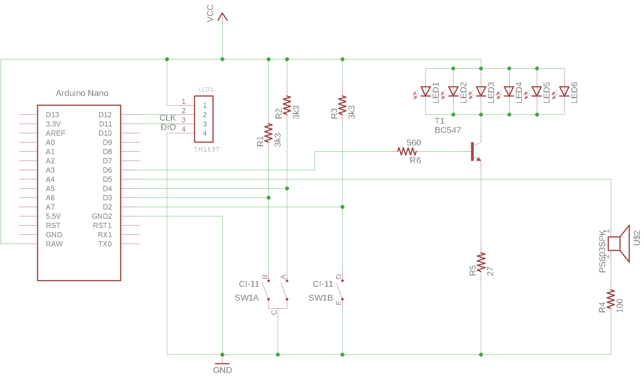
I ordered a 4-digit 7 segment display, a rotary encoder and an aluminium knob, which I planned to run off an Arduino Nano.
Rotary Encoders
A rotary encoder looks a lot like a potentiometer, however they work quite differently. For starters, there is no limiter so they rotate through a full 360 degrees.
But the main difference is how you interface with them: they output a digital code called a Gray code. Named after Frank Gray, it ensures that one-bit only ever changes at one time so we can be sure of the direction the shaft turns.
Of course, the library we are using hides this from us, so all we care about is the value that comes back.
The encoder I’m using also has a push button, which I’ll use to start and stop the timer. The library also abstracts this.
The display
The four-digit seven-segment display has a built in driver chip that means we only need two pins to drive it: a clock and data. Again, there is a convenient library that deals with pushing data to the board.
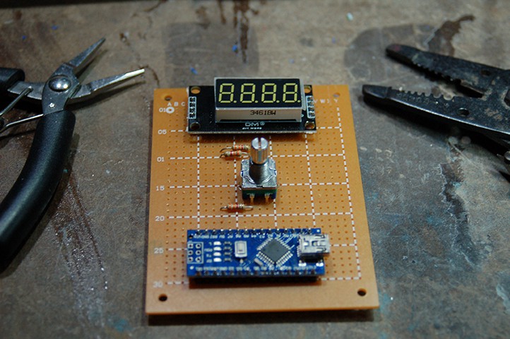
The LEDs
I had six yellow LEDs that I pulled out of the night light I gutted to make an interim night light, so I repurposed them for this project. As the draw a total of about 120mA when on, they can’t be driven by the Arduino directly – I’m using a BC547 transistor to drive them.
The speaker
I added a cheap, 8 ohm streaker than I’m driving directly off one of the Arduino digital outputs. There is a tone librarythat turns a GPIO on and off quickly enough to create a tone. I maybe regretting this already though – it can get quite annoying.
Sleeping
This microwave controller needs to be battery operated. To do that without costing me a small fortune in batteries, the controller needs to turn itself off. Luckily, the Arduino Nano supports a deep sleep which reduces it’s current draw. The Nano can then be woken up by a pulse on either pin 2 or pin 3.
By feeding the signal from the rotary encoder and the switch into those pins, any rotation of button pressing will wake up the processor.
There is a slight problem though: there are two pins on the rotary encoder, and one on the switch: we need another input.
Or do we?
Rotary encoders have a physical “click” (called a segment). On the particular encoder I have, each click goes through a complete Gray code cycle, meaning there is a guaranteed two logic level transitions on each pin per segment. And, if you have ever watched a small child spin a knob, you would have noticed that their developing fine motor skills result in big rotations. In this case I can happily take the output of one of the encoder pins, and be confident that it will always wake.
So, the switch is wired to GPIO 2, encoder pin A is wired to GPIO 3 and pin B is wired to GPIO 4.
The code
There are four main parts of the code: reading the encoder, the display code, the code that puts the MCU to sleep, and the interupt handler that wakes it back up again.
Most of the heavy lifting for interfacing with the encoder and display is done by two libraries.
The encoder library uses polling rather than hardware interrupts (which is good because I would have run out of interruptible pins). Every millisecond it checks the state of the encoder, and can work out if it has been spun or not. This library exposes the delta, we we use to increment or decrement the display.
The library also provides a callback that is fired on button clicks. Each clock...
Read more »


 Dimitar
 Hulk
Hulk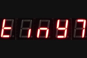
 Alex
Alex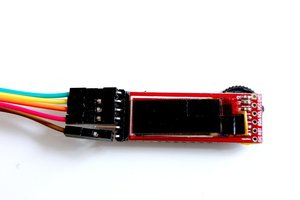
 deʃhipu
Yes it looks amazing I am also working on the similar type of cold press juicer project you can see here.