 Michael
Step 1. Connect to the vehicle CANbus.
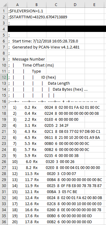
This was relatively simple. I have some basic CAN background experience from my employment. For the purposes of this project log entry, I used a P-CAN USB adapter (gridconnect.com) along with an old OBDII to DB9 connector that I used 5 years ago to read engine diagnostic codes (back with the old ELM OBDII systems). Unfortunately, the DB9 pinnout was very wrong (should have checked first) and when I initially connected the vehicle's OBDII port to the P-CAN tool, I generated 3 dashboard trouble lights. I made a quick DB9M-DB9F adapter that corrected the pinout error...Honestly - I'm not sure why the old cable had the pinout incorrect. Once connected (500kpbs), I recorded a brief CAN trace using P-CAN Basic and then opened it in MS Excel. As shown below, each CAN message contains a timestamp (from the tool), the message ID (which is typically related to some measurable parameter), as well as the data.
Now the harder part comes into play: what do the messages mean?
The vehicle I'm using for this project is a 2011 Toyota Rav4.
I only found one other individual who has looked at late-model Toyotas, as published at the University of Tulsa: Toyota CAN messages. This is exactly what I needed to begin with.
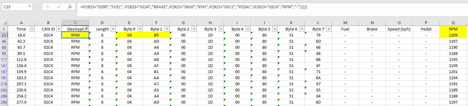
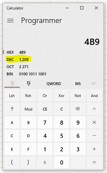
After a little MS Excel manipulation, I was able to sort the data and pick out the meaningful messages. For example, engine speed is extracted from message [HEX] I.D. 0x2C4, with Bytes 0 and 1 (concatenated) then converted into a decimal format as shown below. Note - the order in which the two bytes are concatenated are critical. As an example, 04B9 HEX = 1209 DECIMAL.
Step 1. complete.
Discussions
Become a Hackaday.io Member
Create an account to leave a comment. Already have an account? Log In.