Why?
Me and my wife moved our bedroom from the ground floor to the souterrain and experienced that at night it was even darker than on the ground floor. That's because on the ground floor, light came in from a street-lamp outside. Furthermore there's no socket where we could've placed a night light, which would've turned on automatically when you get up, anymore. That's why I've wanted to build a motion activated night light.
Besides, I'm going to be a daddy really soon (by the time of writing this). Infants are waking up at night because they're hungry (for example). If you're not a cat, you've to turn a light on somehow. My wife thought about placing a small lamp somewhere. I've even heard about women taping a flashlight to the bedpost. But we're in the year 2018 and I had just finished the prototype (stripboard) of the motion activated night light. Therefore I've added a push button to turn on and off the "nursing light mode". The push button is also used to turn on and of the "night light always on mode".
The button turns on the light in a predefined brightness by a short button press. Another short press turns it off again "nursing mode". By holding down the button a little longer, you're able to turn on the "night light always on mode". In this mode the light stays on at a (predefined) low brightness level, instead of turning off completely.
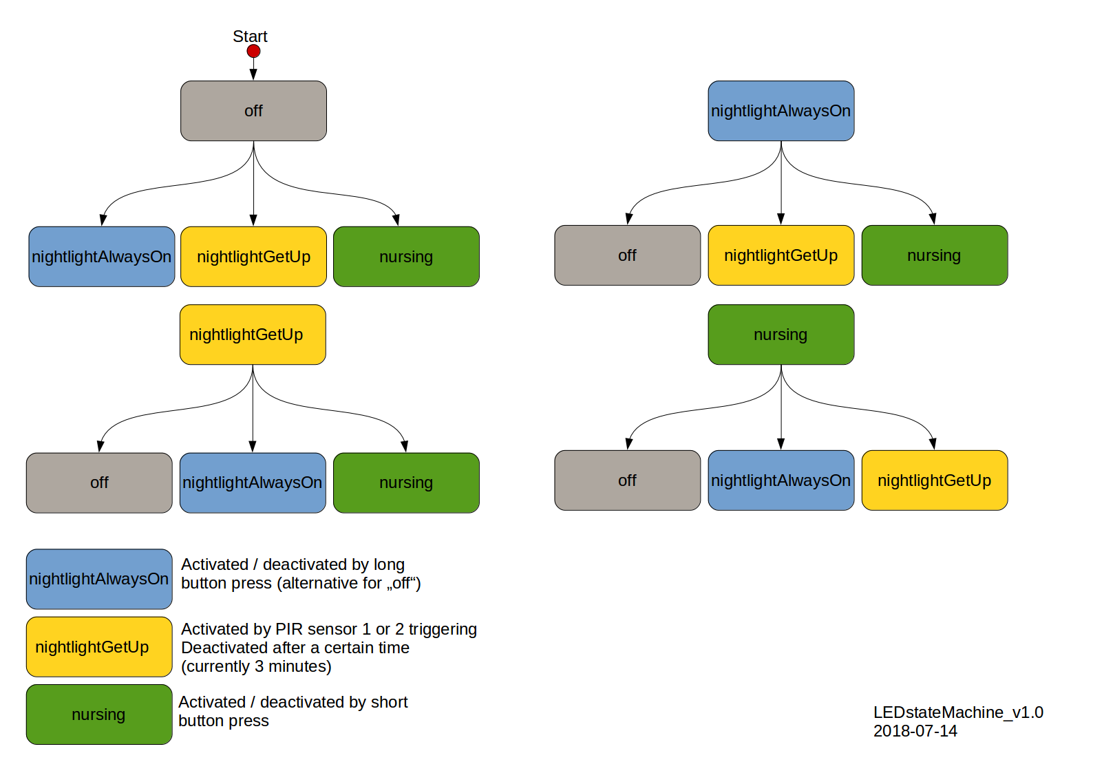
Different modes / states
- off → LEDs are fading down to zero and stay turned off
- night light always on
- LEDs are fading down and stay on at a low brightness
- turn on and off by a long press of the push button
- alternative for "off" (when enabled)
- night light get up
- LEDs are fading up when PIR1 or PIR2 have detected a motion (for example someone is getting out of the bed)
- LEDs are fading down after three minutes (retriggering doesn't expand this time span)
- nursing (the name derived from the main purpose of this light mode)
- LEDs are fading up by a short press of the push button
- LEDs are fading down by a short press of the button
The colors / brightness for every mode is directly set within the code (see future improvements).
Under certain conditions, you can reach each state from one another. I've summarized the different combinations and conditions in the figure below.
LED-fading
Because the brightness perceived by the human eye is not linear, the LED-fading should also not be linear. I'm not going to much into detail here. To my knowledge, it was believed that the human eye has a logarithmical response (honestly, I thought so too until now where I'm looking up a reference concerning this matter). That was until Stevens's power law was introduced. I haven't looked into this any further, but you're free to do a research on your own. I'm glad to provide some links as starting points: Apparent magnitude, Stevens's power law, Power law.
Nevertheless, it is obvious that a non-linear approach is the way to go. And because I wanted the fading (PWM) to be super smooth, even when it runs very slowly, I've chosen to use 16-bit timers. I'm using these in fast PWM mode. Please check the datasheet of the microcontroller for further information regarding this.
Controller board
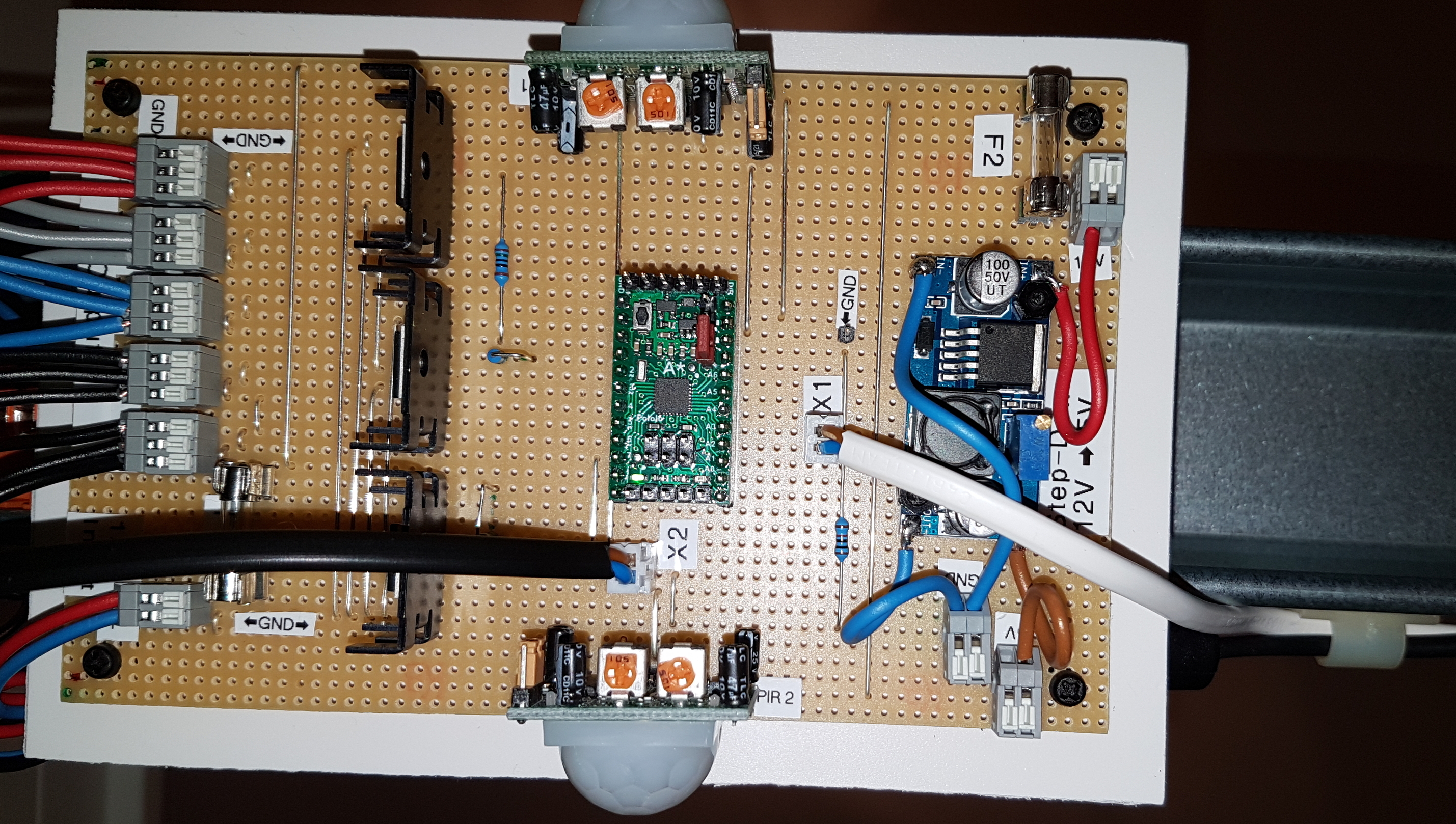
The prototype of the controller board is installed on a stripboard. That was really useful regarding the position of the ambient light sensor (more about that later) and for adding the push button. The controller board consists of these parts:
- Input terminals → 12V/5A supply voltage (protected by a fuse)
- Step(Up)Down module 12V → 5V (one of the ready made modules from China protected by a fuse. I'm going to use a smaller one on the non-stripboard PCB but I had this one at hand)
- Connector for the push button
- Two PIR-sensors
- Connector for the ambient light sensor
- Microcontroller ATmega328PB (the B is important, because this version has three 16bit Timers instead of one, which I'm all using for the LED-fading; again, I'm using a module here - in my case the Pololu A-Star 328PB Micro)
- MOSFETS for driving the LEDs
- Output terminals (for the LED strips)
I've mounted the controller board under my bed (in the middle near the end). I've used a PVC plate and cutted four M3 threads into it where I've installed the spacer on which I've installed the PCB (secured with nuts). Another thread (M4 I think) goes into the middle of the PVC plate. I've installed silicon strips on the PVC plate to decouple the controller board from the metal bar of the bed. The bar sits in the middle of the bed and already has some holes. I used one of these to mount the PVC plate via the M4 thread. The PIR sensors are facing to the long sides of the bed.

LED strips
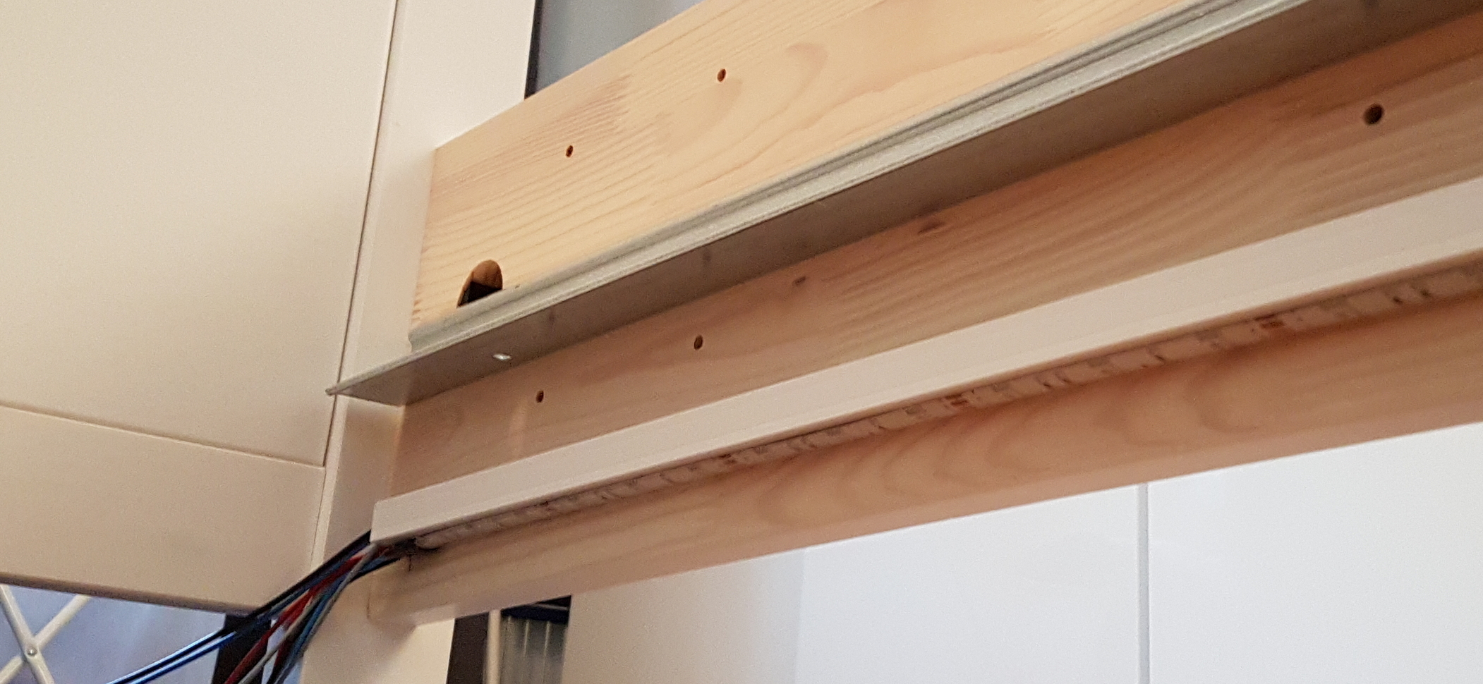
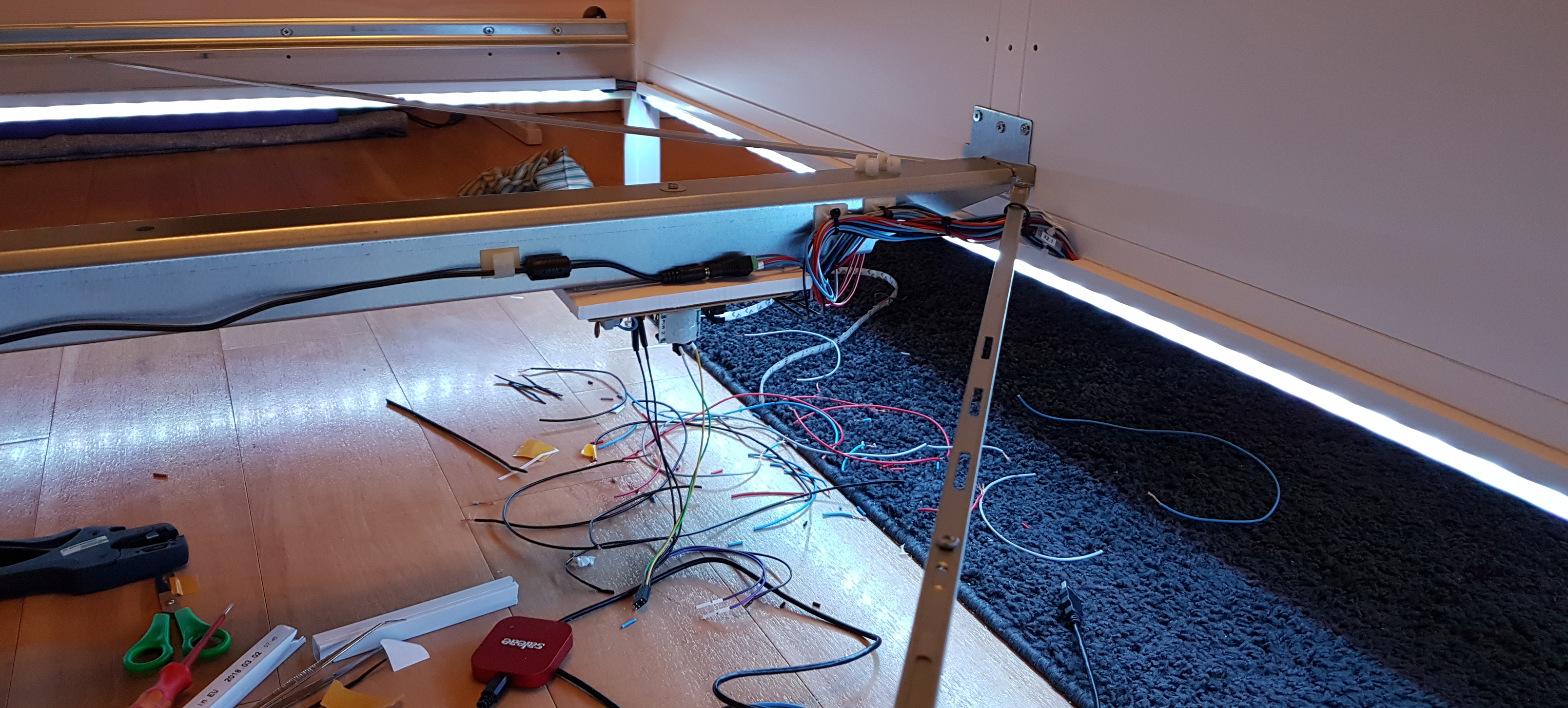
First of all, I've cut the LED strips into three pieces (2x long side, 1x short side at the end) and soldered four wires to both ends of each strip (+12V = black wire, red GND = red wire, green GND = gray wire, blue GND = blue wire). I wanted to mount the LEDs in a way that they're facing downside and aren't visible from outside. Therefore I've used cable duct (15 x 15 mm) which I've cut to length accordingly to the LED strips / the bed. The benefits of using cable ducts are: It's cheap, easy to get, easy to work with, has a smooth surface and you can use it to organize the wires running along the bedframe. I've used the adhesive tape on the strips to mount the strips on the cable ducts and applied double-sided adhesive tape to the cable duct in order to mount these on the inside of my bedframe. This worked in the beginning but after a few days / weeks, the cable ducts fell of. I've a wooden bedframe, maybe it's getting bend to much while getting in and out of the bed? Nevertheless, I've used small screws (3 x 10 mm) to mount the cable ducts to the bedframe. Since than it's working very well.
Ambient light sensor
For determining the digital values to the corresponding analog values, I've created a spread sheet. You can check it out here: ***I'll add a link later*** To test it, I've toogled some pins according to the results of the ambient light sensor, recorded the digital states and the analog value of the ADC input with my logic analyzer from saleae.
During testing, I've experienced, that the measured voltage is swinging while using the ambient light sensor and AC-powered LED light bulbs. Keep that in mind when installing the sensor.
In the first iteration, I've mounted the sensor directly onto the controller board. Unfortunately, it wasn't able to tell night from day (it was always night under the bed). That's why I've unsoldered the sensor, soldered a connector onto the stripboard and moved the sensor to the bed-head. Because I haven't tested the values under the different lightning conditions in my bedroom, the results of the sensor aren't used by the current software. A function to get several values and calculate the arithmetic middle does exist and is working.
Push button
I've ordered a bunch of push buttons and let my wife decide which one she likes best. She settled on a full metal one (often used for doorbells / mounting hole diameter 19 mm / mounting depth about 25 mm / overall length about 28 mm / NO). My first idea was to design a housing with magnets at the bottom to attach it to the metal stand of her reading light. The light is standing on her bedside table right now. But since the bedside table is going to make room for the baby bed and my wife told me she would like me to mount the button at the bed-head, I'd to think about another solution.
I came up with a case which has "ears / wings" attached to its side. This way it's easy to mount the button to the bedpost using a rubber band. It's not necessary to screw or glue something to a (visible) part of the bed. And it is very easy to change the mounting position.

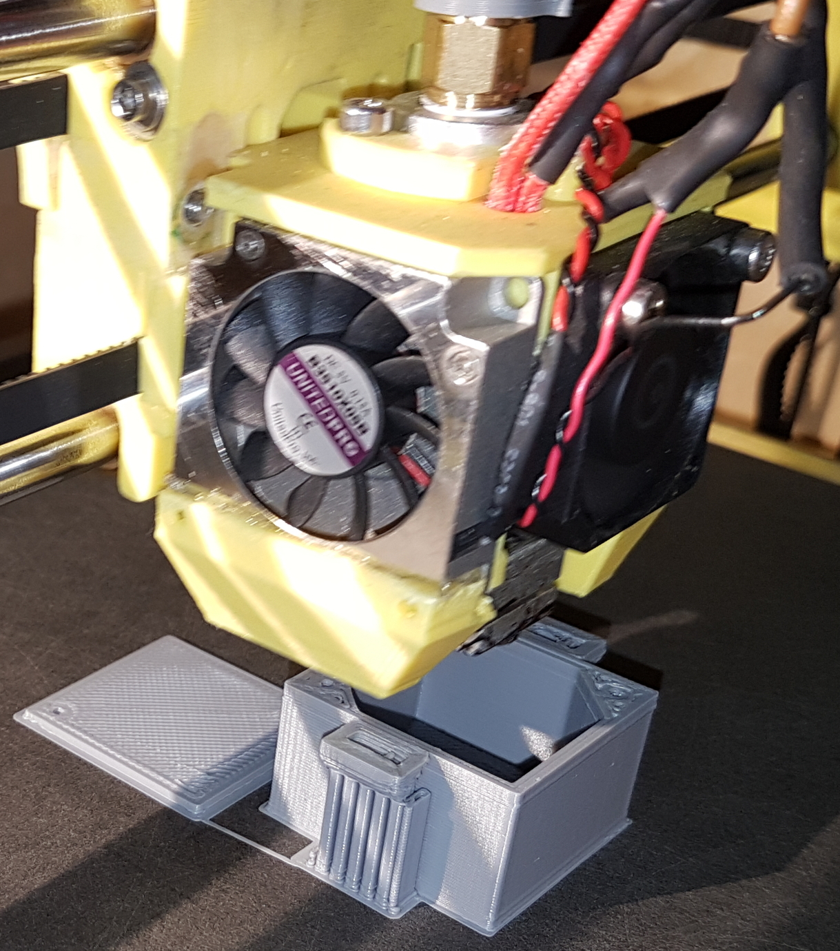
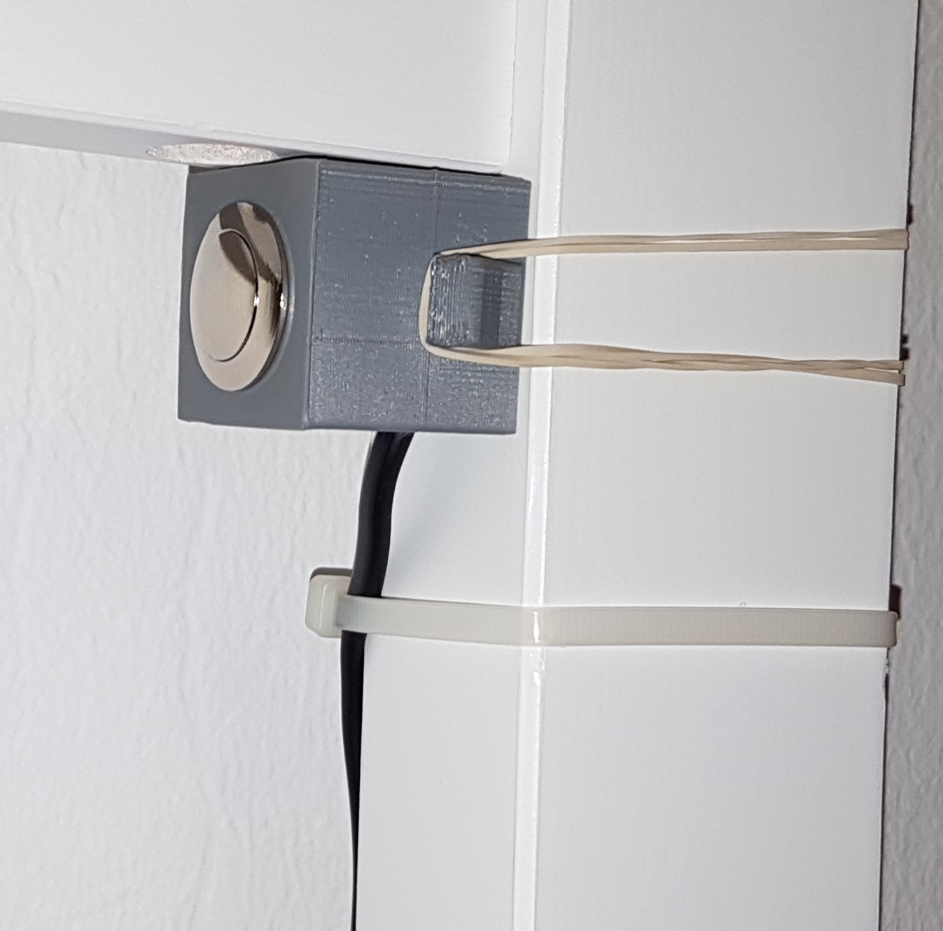
The part of the bed where I've mounted the button has a depth of 36 mm. Since the button is facing to the inside of the bed, the width of the case shouldn't exceed the 36 mm too much. I've designed the housing without a lot of extra space and just gave it a try.
My 3D-printer isn't calibrated yet (I'm going to change something before continuing with the calibration) but I had to use it anyway ;-). Regarding the printing quality, there is definitely room for improvement. But please keep in mind, that the printer isn't calibrated, I don't have a lot of experience with 3D-printing yet and this is the first "real" object my printer created.
I milled a hole for the cable inside a wall of the housing, reworked the mounting hole for the push button a little bit and sanded the sides of the cover until it fit into the housing. Because of the size of the housing, it was tricky to fasten the nut to the push button which is holding it into place. I've used a screwdriver and tweezers to get the job done. The strain relief is realized by a cable tie.
I've tried to use 2 x 12 mm screws to attach the cover to the housing. Therefore I've used a countersink to work on the holes of the cover. In the end, I didn't used screws for my first try and only placed the cover within the housing. The cover has to be a little sicker and the holes are too close to the sides to hide the heads of the screws completely. It's possible to reduce the space within the housing a little bit more. I think I'll be able to adjust the housing so that the screws fit and the overall size does not change. I've to print the case in white anyway ;-)
Recommendations
Think about connectors for separating the LED strips in case of dissembling the bed (I didn't think of that before hand but my wife pointed it out...).
The A-Star 328PB Micro I'm using comes with a preinstalled bootloader. If you're not using it, you should change the fuses. I'm flashing the controller over ISP, therefore I'm going to change the fuses accordingly (still on my 2do list).
Future improvements
- change fuses (because I'm not using a bootloader)
- enable internal pullups for unused pins (to save power)
- make it more user-friendly
- Set brightness / color, time on duration, fading-speed and ambient light sensor threshold via some setup mechanism (setup mode / existing button / other buttons / potentiometers) or via a connection using bluetooth or wifi (by adding an ESP32 for example)
- implement the ambient light sensor
- check if it works in the current environment
- remove / handle voltage "spikes" within the analog measurement [I'll write about it in a project log when working on it]
- if they're coming from the timer overflow: Invert PWM; "spikes" should than appear at full brightness instead of lowest brightness
- if inverting the PWM doesn't work, filter spikes (either hard- or software) to get a working arithmetic mean value for the analog reading (ambient light level)
- implement sleep modes (maybe even let the user choose if they're using
the push button or not [jumper] → different sleep modes are possible, because the button needs a timer interrupt, the PIR sensors are connected to the interrupt pins AIN0 and AIN1) - LED-Fading
- there is a delay after reading a value for the LED-fading from the designated table. Remove delay if this value is <= the current brightness (for a specific color) when fading up or if the value is >= when fading down
- extend current LED-fading functions (up and down) to check if they've to go up and down to reach the target brightness level and act accordingly (right now it's directly set in my code for my current setup)
- During night light get up mode: Before exiting, check if PIR1 or PIR2 are triggered right now. If so, stay in this mode until they aren't triggered anymore. Benefit: LEDs wouldn't fade down and fade up directly after.
- add component list
- housing
- push button
- adjust the housing to be able to fix the cover using screws
- improve print quality while using white filament
- PCB (stripboard) → create a housing
- PCB → create a housing
- push button
- PCB
- design a professionally made PCB
- add test points
- add the possibility to attach the PIR sensors using connectors if the position of the PIR sensors on the controller board is not suitable for the designated environment
- add more terminals to connect all the wires
- use plugs to easily detach the controller board
Thank you!
[check the links on the left]
Projects like this wouldn't be possible or a lot harder to realize if the great hard- and software I've used so far wouldn't exist / be available. Most of it is even open source! Thank you very much (alphabetic order):
- AVRDUDE (in combination with the Atmel / Microchip toolchain)
- Geany (Editor)
- FreeCAD 0.17 (stable release)
- LibreOffice Draw
- MKC MK2 (= Mein kleiner Core Make 2) v1.0 (3D-Printer developed by alejanson)
- Saleae Logic 1.2.21 (and up) [beta release]
- Ubuntu
I also want to thank Andre Moehl for his explanation on how to get the toolchain for the ATmega328PB working (I had some trouble with that in the beginning).
My special thanks go out to:
- Peter Danneger for his unbelievable good timer based debounce routin
- The authors off the LED-fading tutorial over at mikrocontroller.net
- Saleae for there awesome logic analyzer(s) with it's brilliant software with analog measurement capabilities and the new live view feature (beta). It helped me a lot during this project and it's going to do so in the future (I know that I've listed Saleae already but it's just great).