- Introduction:
- In photovoltaic systems, solar tracking mechanisms help minimize the angle of incidence (the angle that a ray of light makes with a line perpendicular to the surface of reception) between the incoming light rays and solar panel, which increases the amount of energy that an installation produces. In simple words, solar trackers continuously direct solar panels or modules towards the sun for better energy output.
- Although the invention of a tracking mechanism was a breakthrough in harvesting solar energy more efficiently, the contemporary implementations of solar tracking mechanisms have some significant drawbacks.
- Through this project, I offer an alternative design which is significantly more efficient in terms of power output, durability, production cost and repairability than contemporary models.
- Objective:
- Most contemporary implementations of the solar tracking mechanisms in all solar installations around the world are completely “programmed”. The mechanical solar seeker aims to improve the efficiency of contemporary “programmed” tracking mechanisms by only “electromechanical” means.
- This project also aims to offer a low-cost solar tracking solution so that solar powered systems can be easily installed and maintained in under-developed and developing countries.
- Materials used:
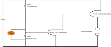
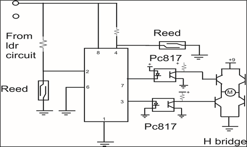
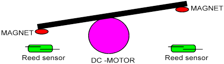
- Light Dependent Resistor (LDR), two solar panels, fours NPN transistors, two reed switches, IC 555 components, assorted resistors, 1000 µF 16 V capacitor, Two BC 557 transistors (PNP), Light Emitting Diodes (LEDs), 12 V DC gear motor, battery power source(9V), one battery clip, two magnets, wooden frame.
- Underlying Principles of Operation and Innovation:
- We first discuss the operation principle of a contemporary programmed solar tracking mechanism and then that of our mechanical version.
- Programmed Solar Tracker :
- On the sunlight reception surface of the programmed tracker, there are a large number of light dependent resistors (LDR) which show variable resistance depending upon the intensity of light falling on each of them.
- The intensities of sunlight received by LDRs on two halves of the sunlight reception surface help in figuring out the position of the source of light. A ratio of intensities of light falling on two halves of the surface is computed as per the resistances shown by the LDRs embedded in both the halves.
- This ratio, computed by an appropriate program, tells the microcontroller to turn the frame (or sunlight reception surface) towards the source of light till the intensities of sunlight on both halves of the surface become equal to each other i.e. the intensity of sunlight falling on the surface becomes uniform which will also be the maximum intensity of the source of light.
- Some drawbacks to be noted about the programmed tracker:
- The programmed tracker “tracks” sunlight at every small instant of time. As soon as the ratio of intensities on the two halves of the surface changes, the microcontroller turns the surface to attain equilibrium. However, this feature of continuous movement is not really necessary because the sun undergoes an extremely small displacement from its position in small instants of time. In such cases, energy lost in moving the surface towards source of light is more than that gained by the tracker. (DRAWBACK 1)
- As the programmed tracker continuously tracks sunlight, a program logic is carried out at all times to compute the relevant intensities. This is the most energy consuming process in the programmed tracking mechanism. Even when the surface is positioned to receive maximum intensity of light, the program logic keeps on consuming energy. (DRAWBACK 2)
- Broadly speaking, we also understand from the above discussion that a solar tracker carries out two basic processes:
- Moving the reception surface (or frame) towards the source of light. This process is termed...
 kutluhan_aktar
 Open Green Energy
 Andrea Console
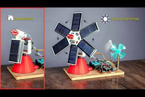
 NextPCB