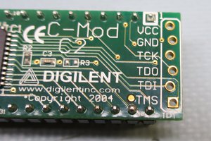
What you basically have to do is remove UC3 from your VC1541 (you can reuse the MCS6522 from there on the board) and put the modded board there.
Then you have to remove UB4 with a EPROM with the modded firmware. You need a 2364-EPROM for this, but you can solder an adaptor for 2764-compatibility.
Partlist:
C1, C2, C3, C4 100nF ceramic
D1, D2, D3 diode 1N4148
R1, R2 3,3 kOhm resistor
IC1 MCS6522 (from VC1541)
IC2 SN75160
IC3 SN75161
IC4 74LS136D
JP1, JP2 2,54mm 2 Pin single row pin header
S1 2,54mm 20 Pin single row pin header, 2 pieces, back side for connection VC1541
S2 2,54mm 24 Pin header double row angled
Pin numbering S2 (looking on the pcb, S2 lower right):
Upper row 1 to 12 from left to right, lower row 13 to 24 from left to right
Pinout (1-24):
D1, D2, D3, D4, EOI, DAV, NRFD, NDAC, IFC, SRQ, ATN, GND, D5, D6, D7, D8, REN, Rest GND
Connect S2 like shown with 24-pin Centronic-Plug
Good luck!

 MagicWolfi
 Pnoxi
Pnoxi

 Alpenglow Industries