 T. B. Trzepacz
Entries for the Hackaday Prize are required to disclose the licensing terms of all of the software used in the project.
This project is licensed under the Creative Commons 4.0 Share Alike Non-commercial Licence.
This project includes the Mozzi audio library, which is also under this license and this it is required.
This project also uses the Arduino IDE, which is licensed under LGPLv2.1.
This project also uses STM32Duino libraries and utilities for supporting STM32 Blue Pill boards.
These libraries include ST-Microelectronics Driver Code licensed under the BSD 3-Clause License, middleware licensed under the MCD-ST Liberty SW License, and the Apache License.

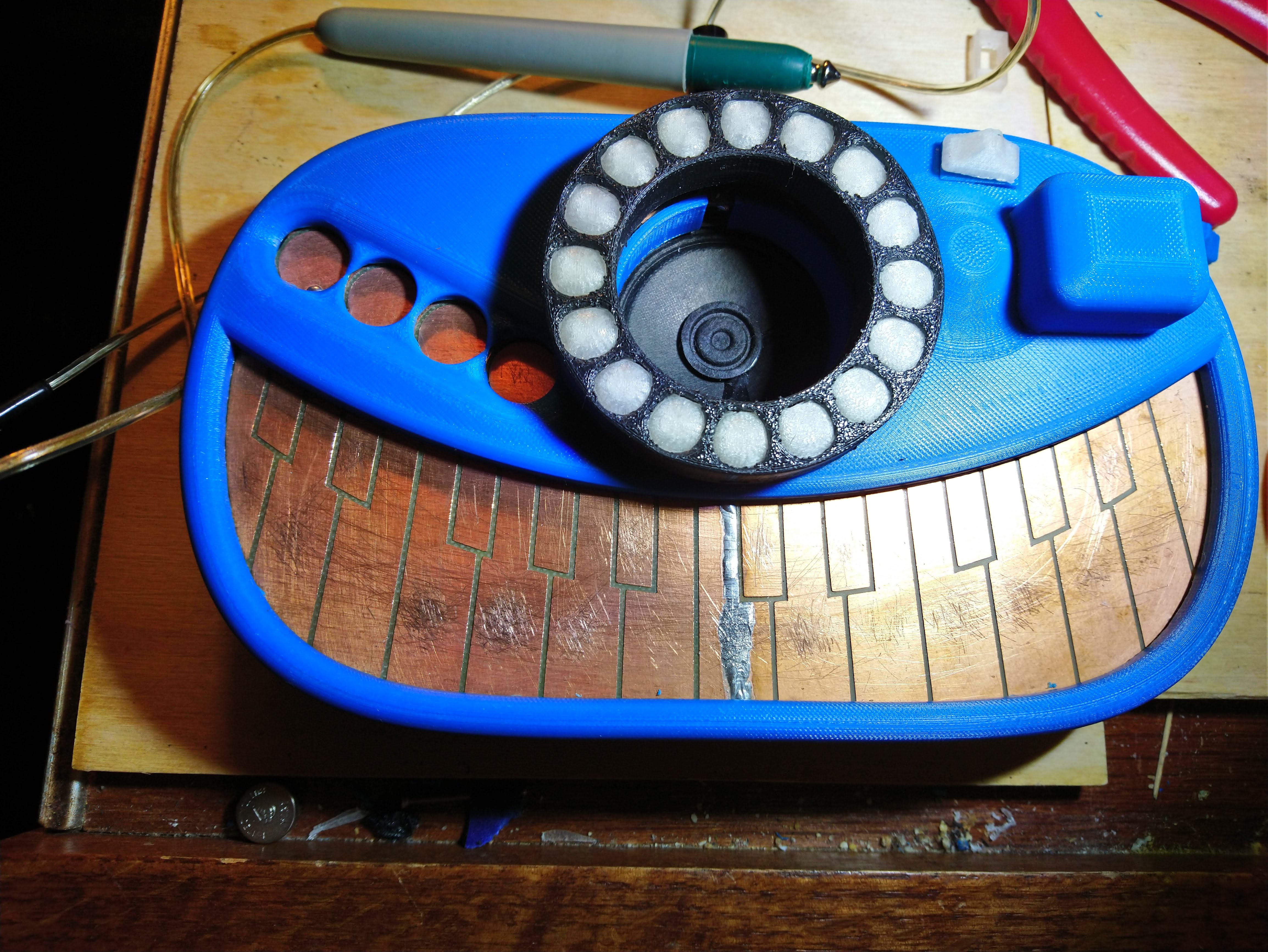
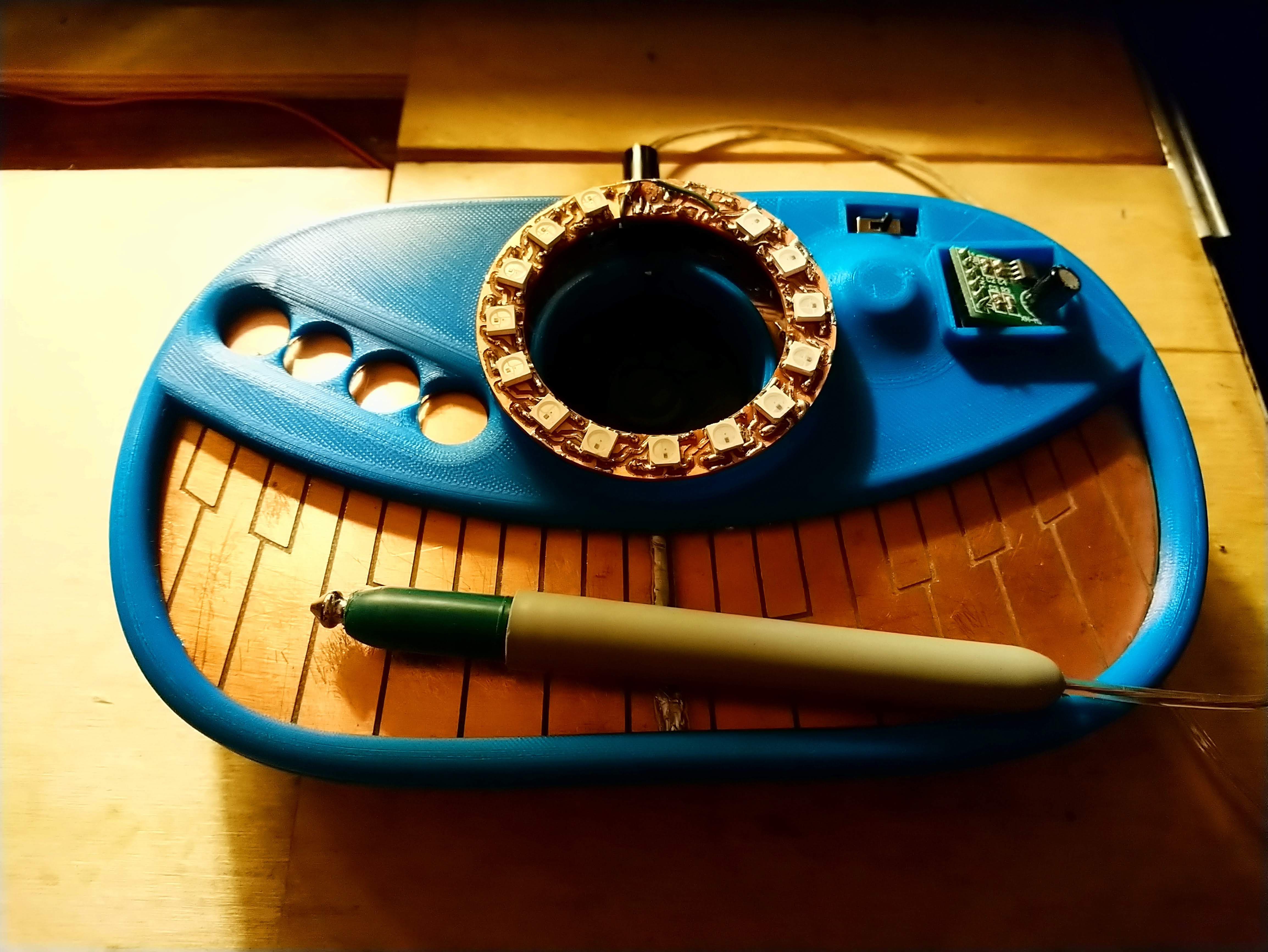
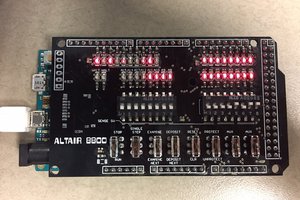
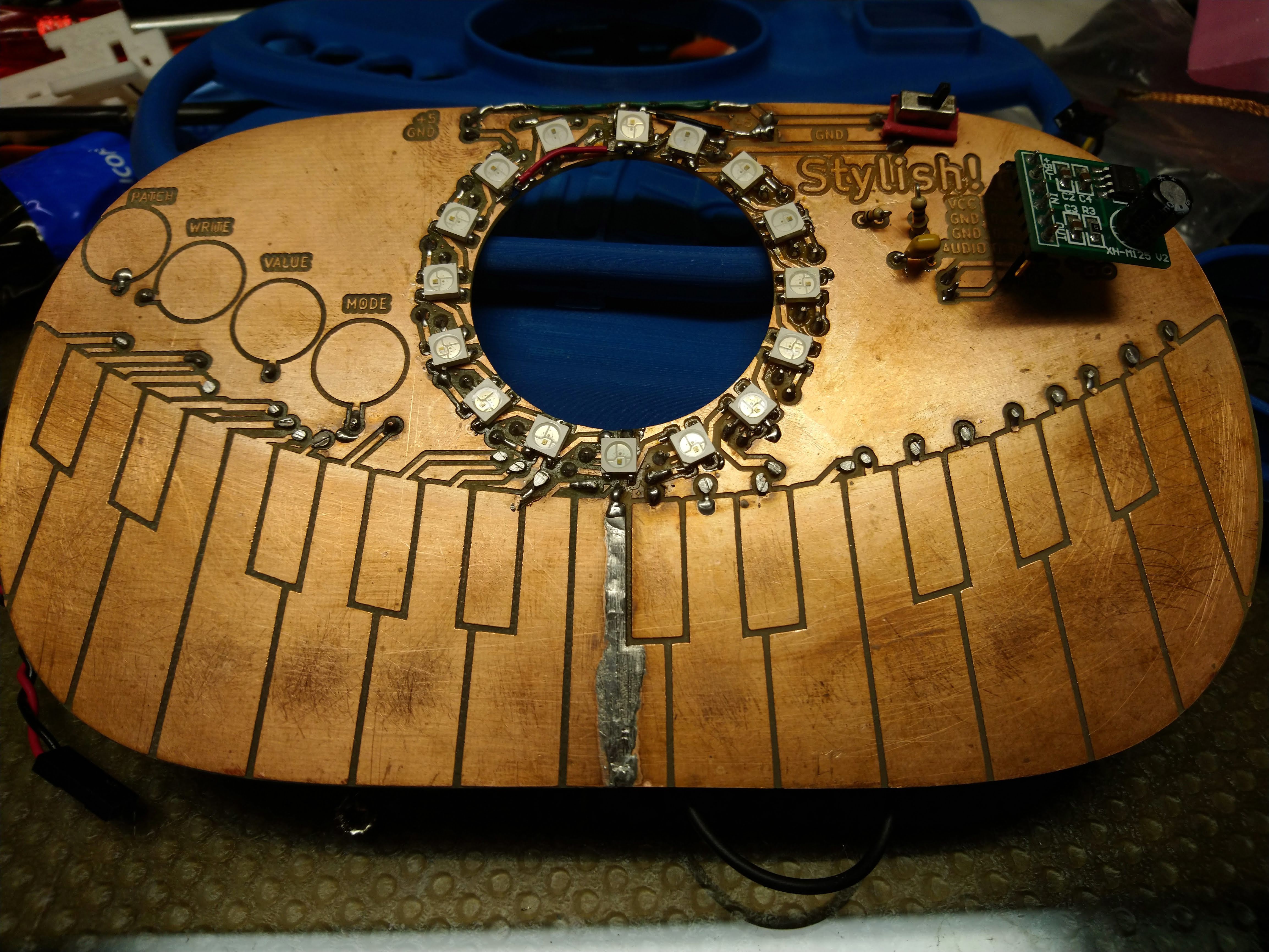 It took some debugging, as there was one bad LED in the bunch that had to be replaced, and I had to wire one LED completely floating in the air...
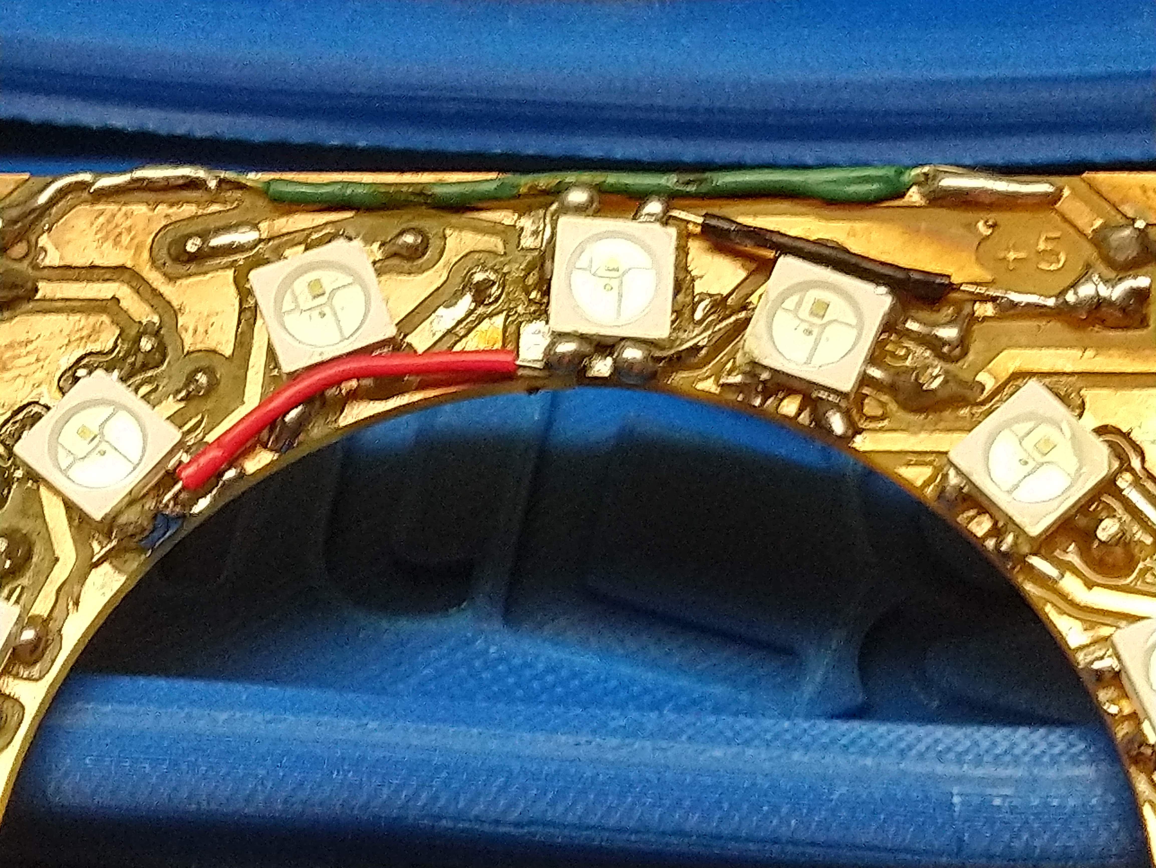
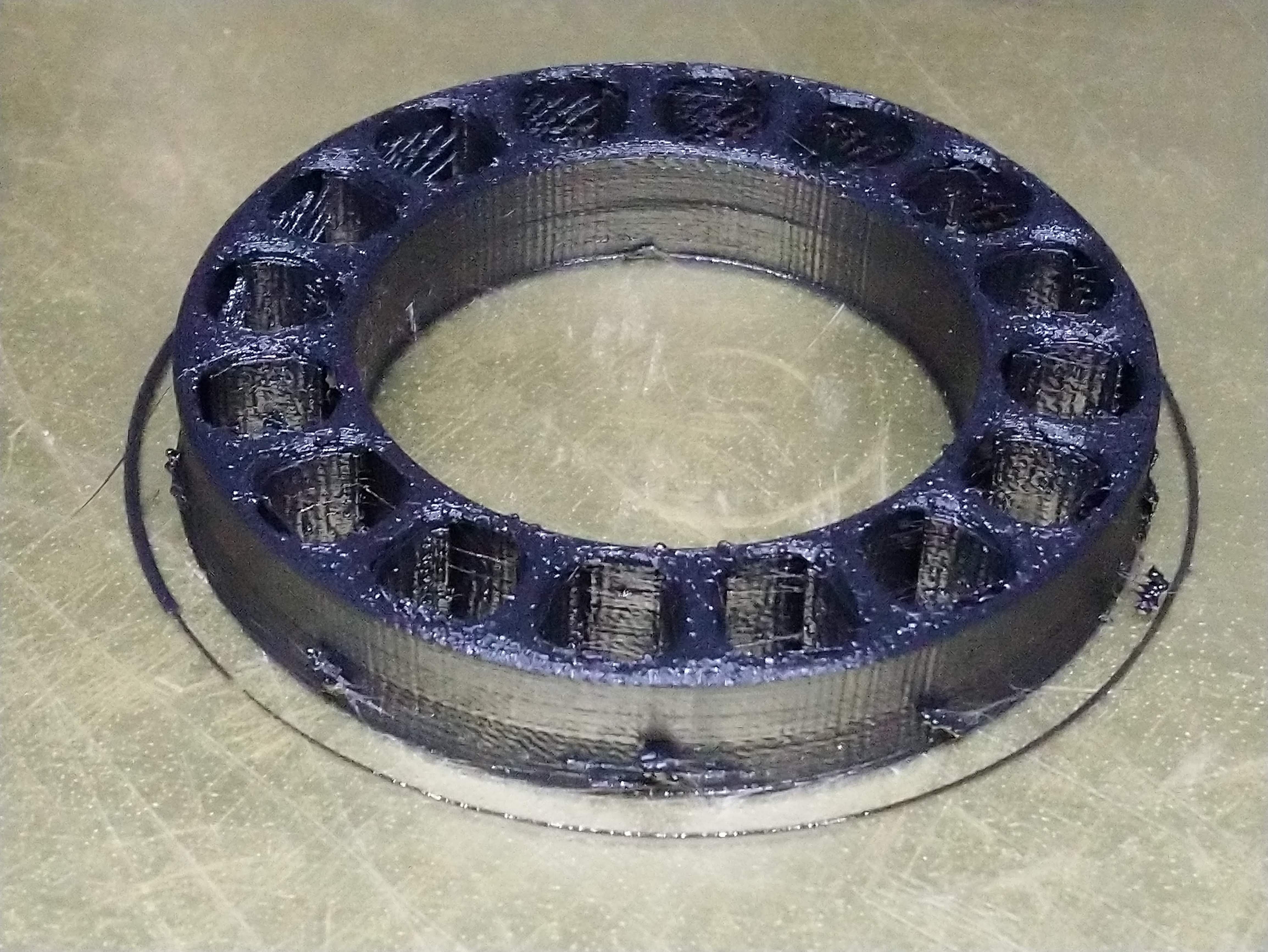
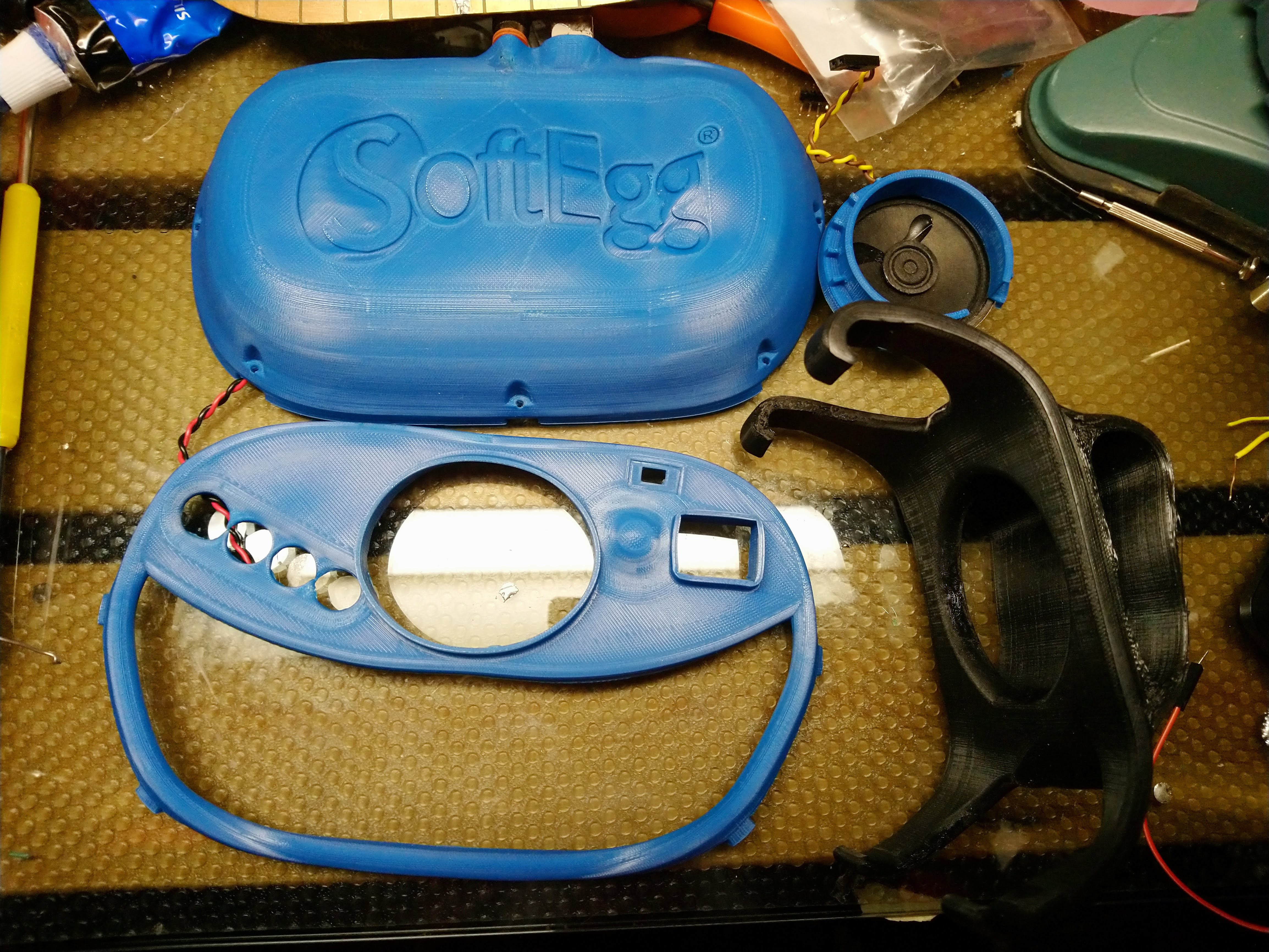
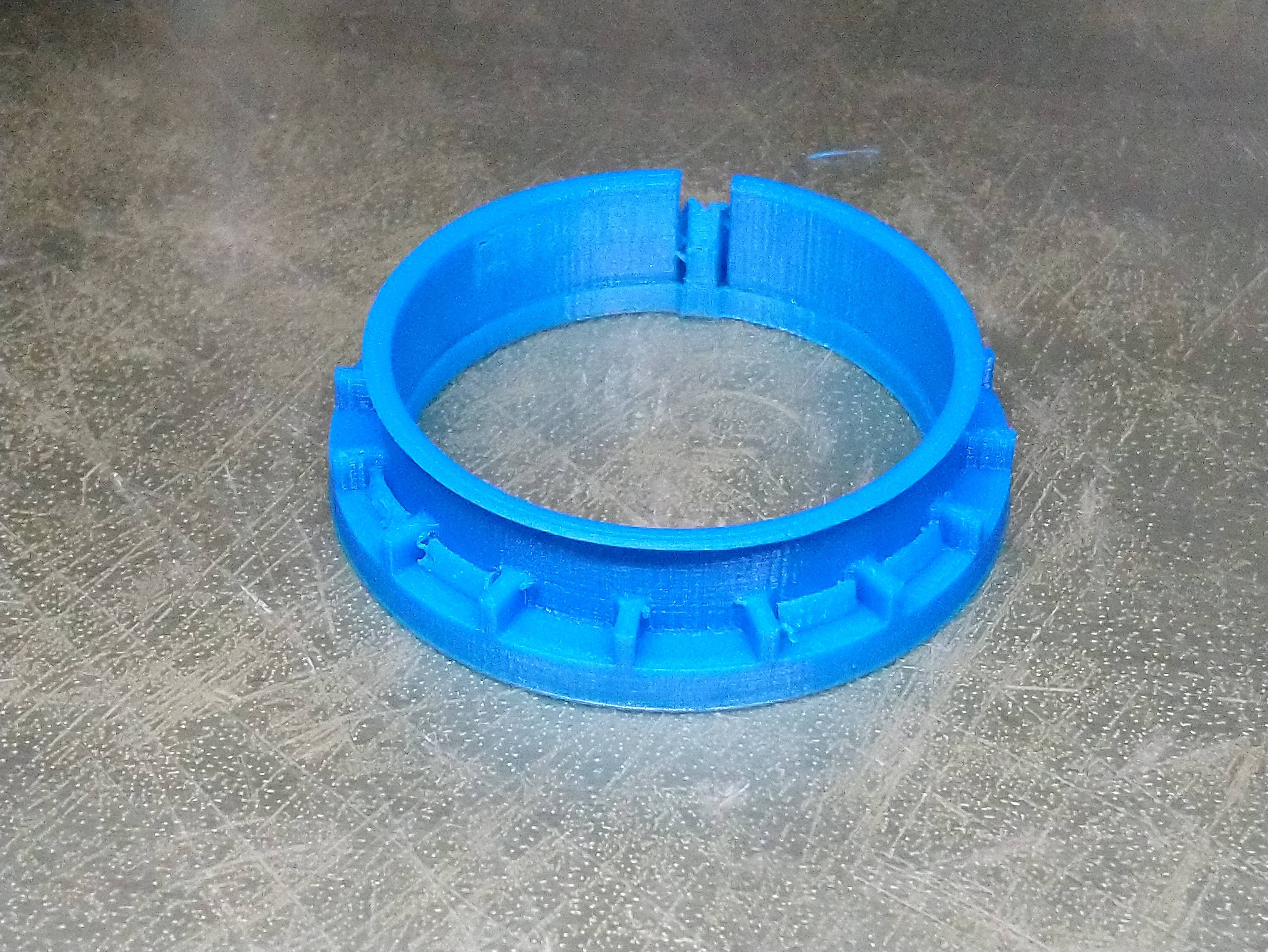
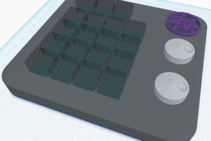
 Printed the bezel in "natural" PLA filament. It turned out that all of the soldered vias on my homebrew 16 LED ring were pushing it up, so I ended up printing it again. That one also didn't fit, so I ended up going at it with nippers until it kinda fit.
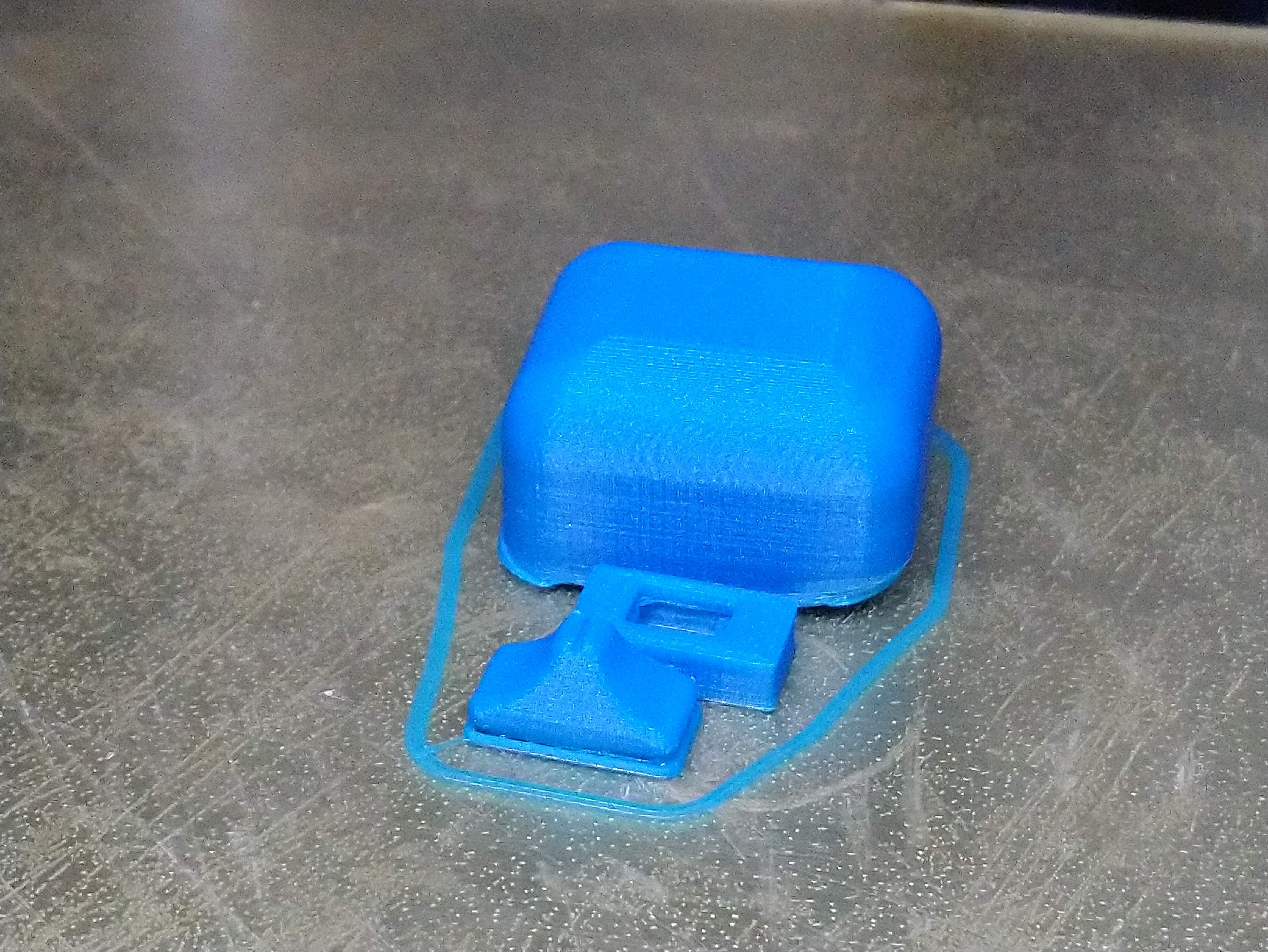
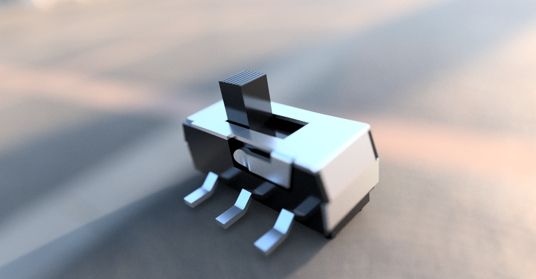
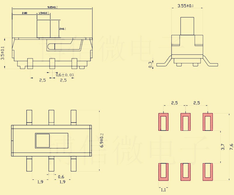
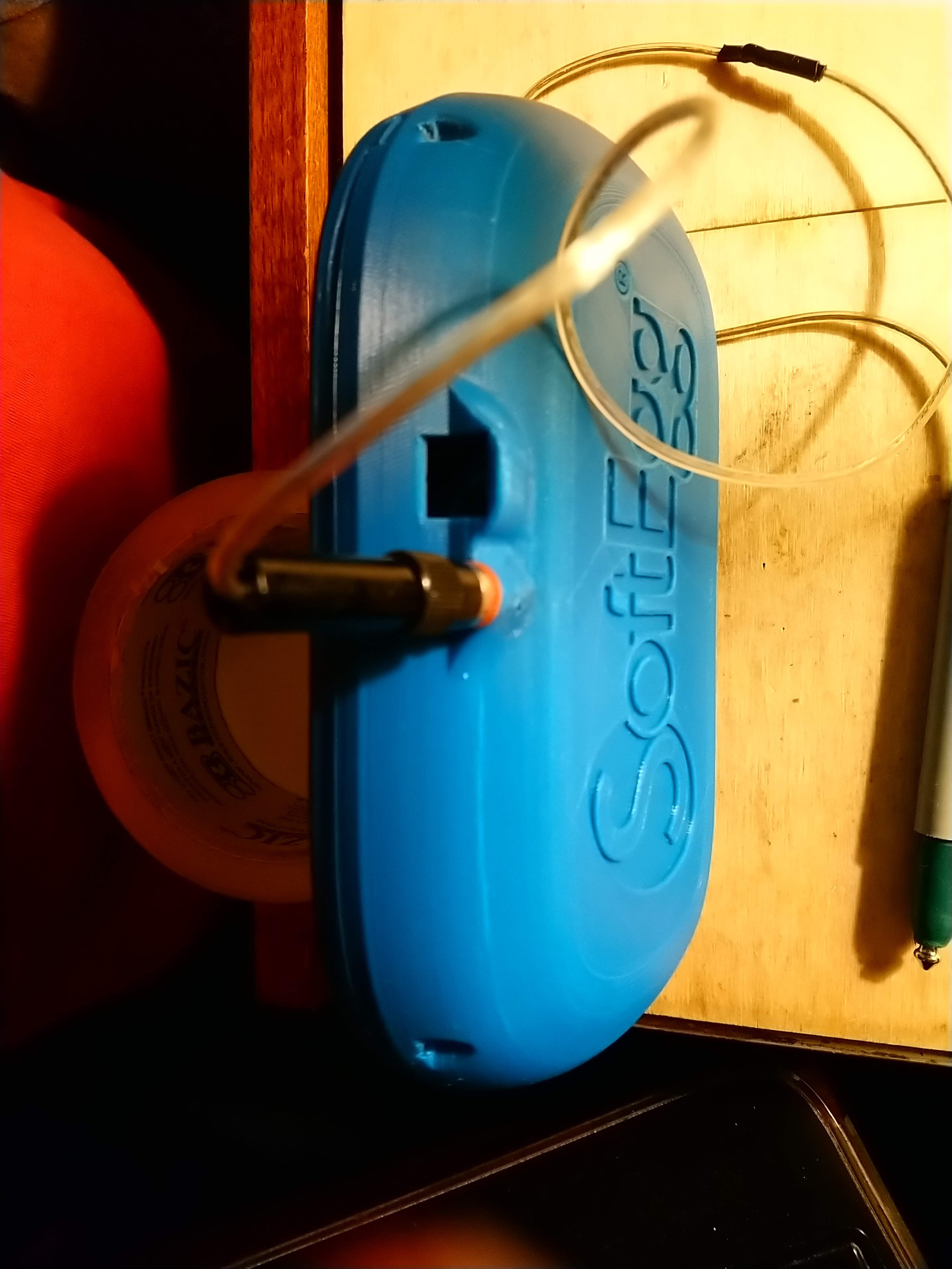
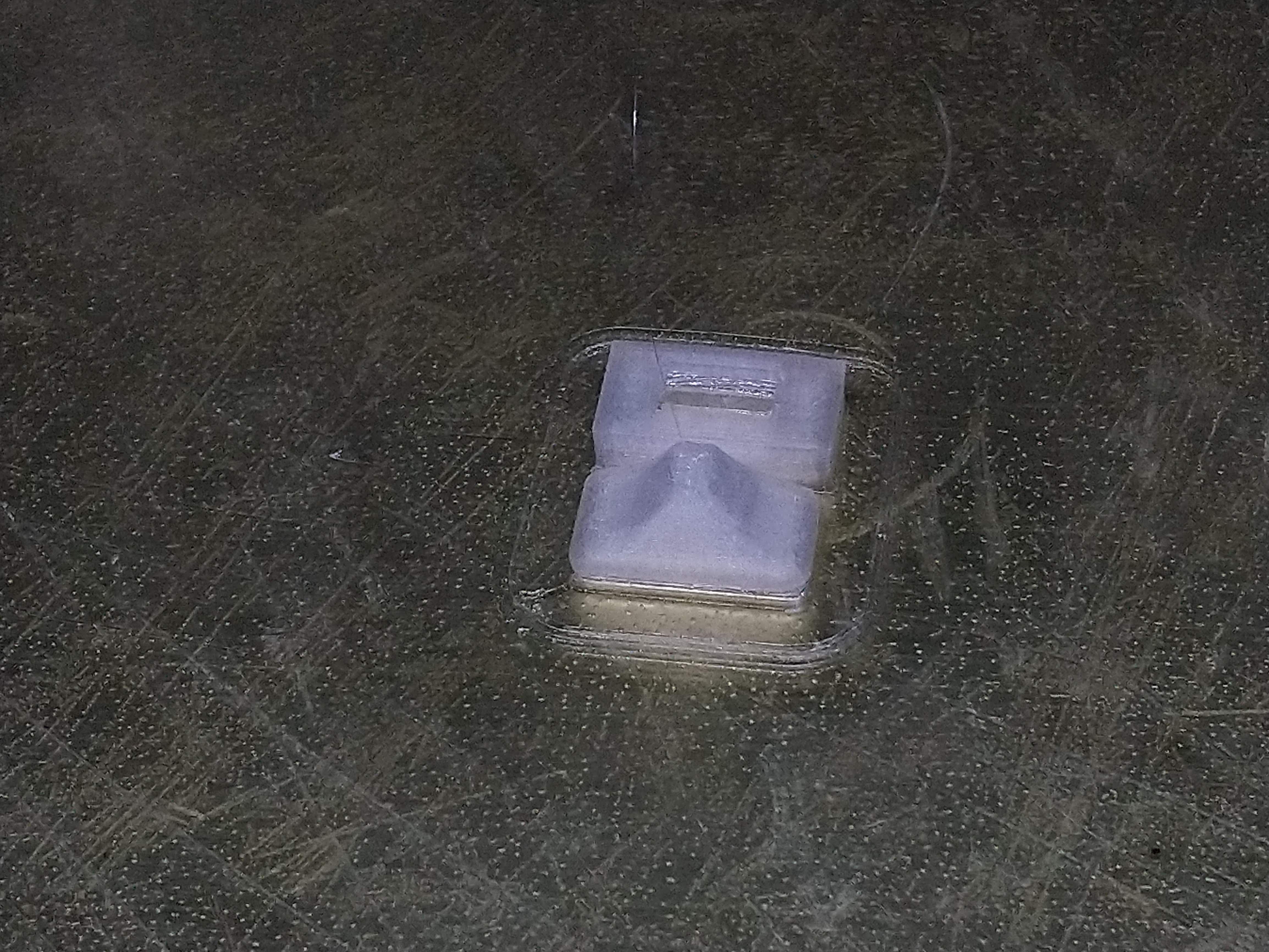 I also needed to make an end for the switch and a plug for the hole in the case for the switch that is too big.
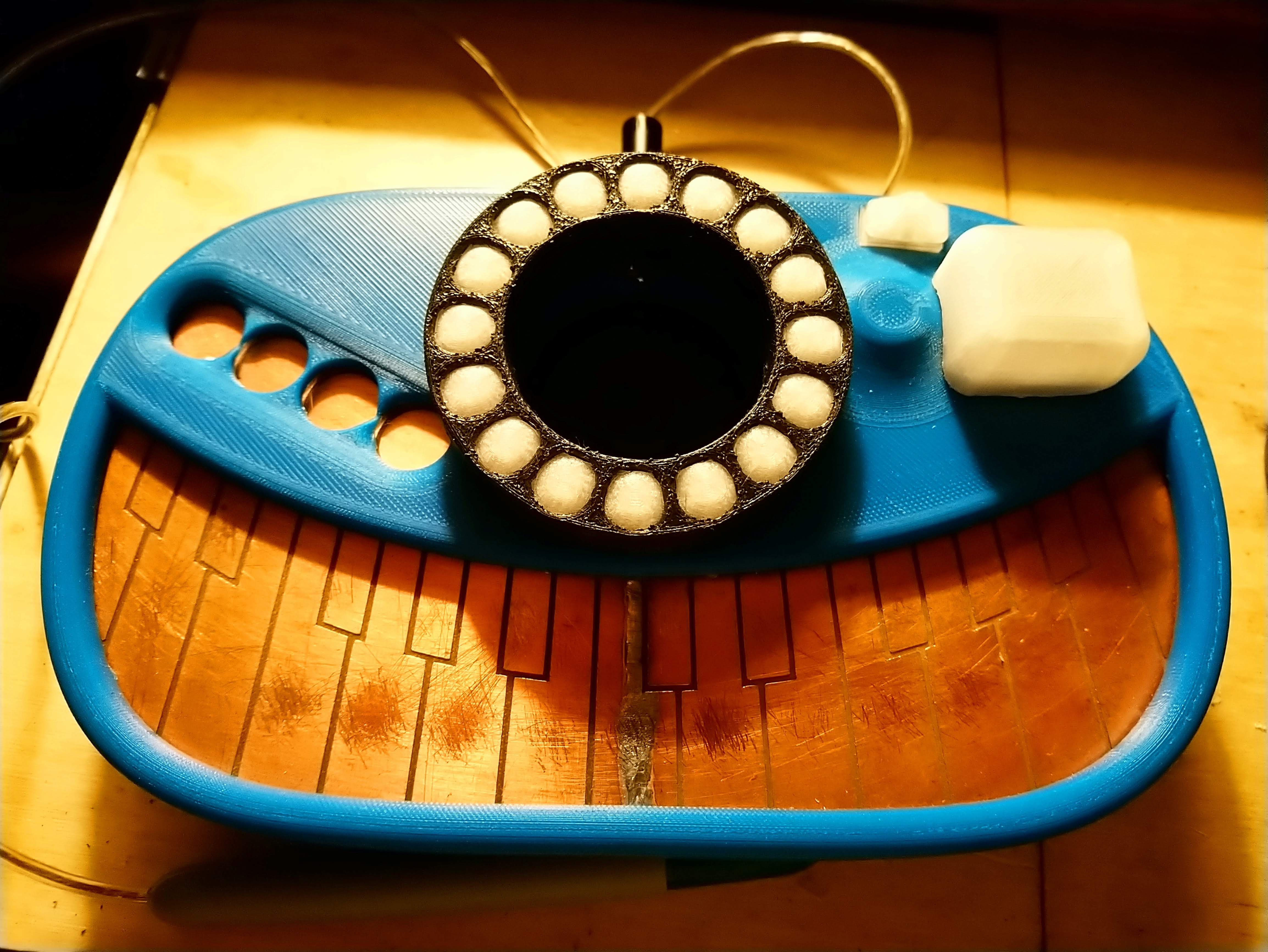


 mrpendent
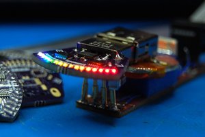
 zakqwy
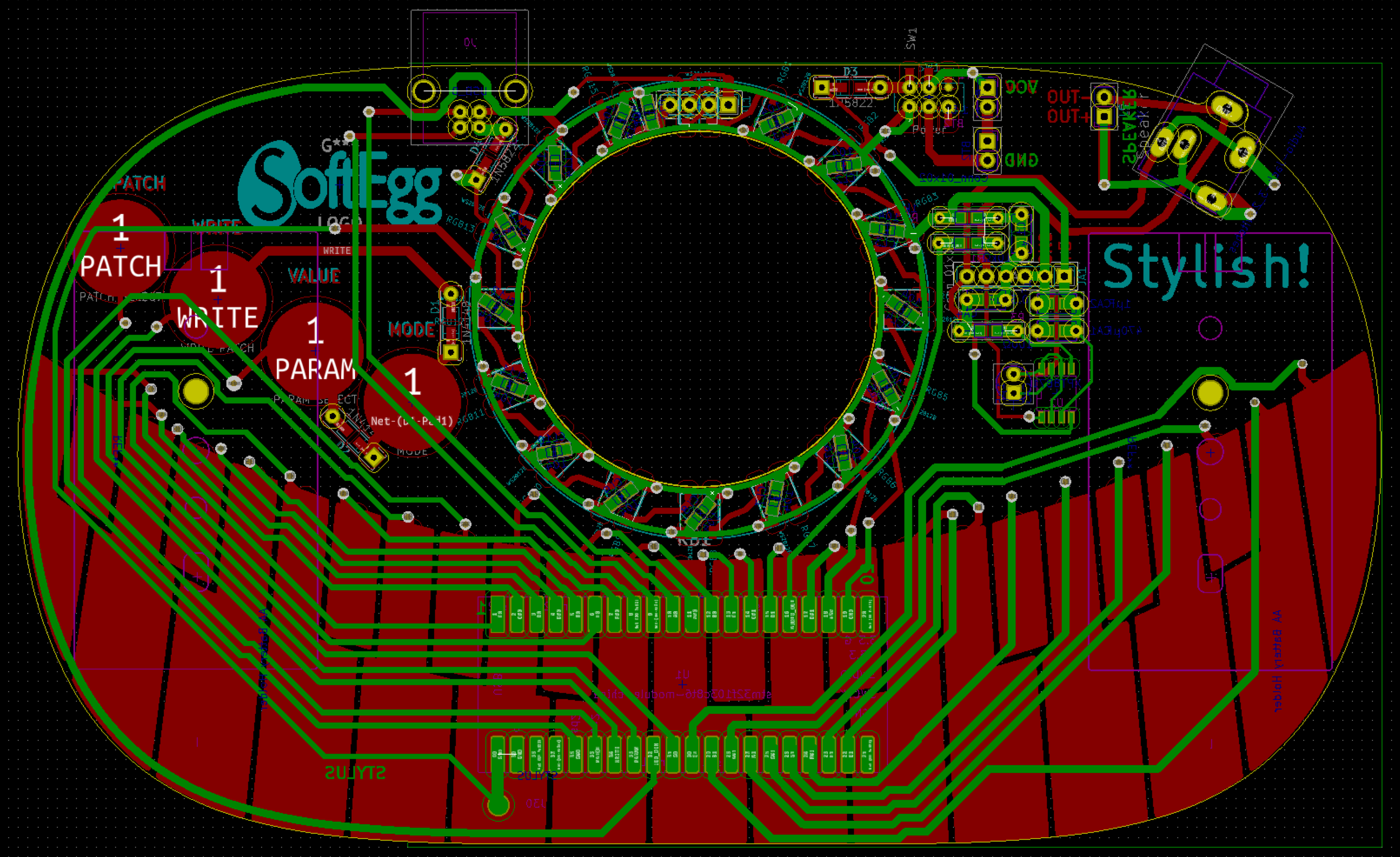
That's surely a most elegant board layout. Hats off to you, mainly for that mad presentation video And Cutest layout Resso Music App. https://theressoapk.com/