 Ken Yap
Prologue
First off, this is not cutting edge. If anything it's trailing edge.
In the late 1980s I bought a digital clock with large neon digits from a disposals store. I liked that the digits were 5 cm tall and a beautiful amber.
Here's the front of it:
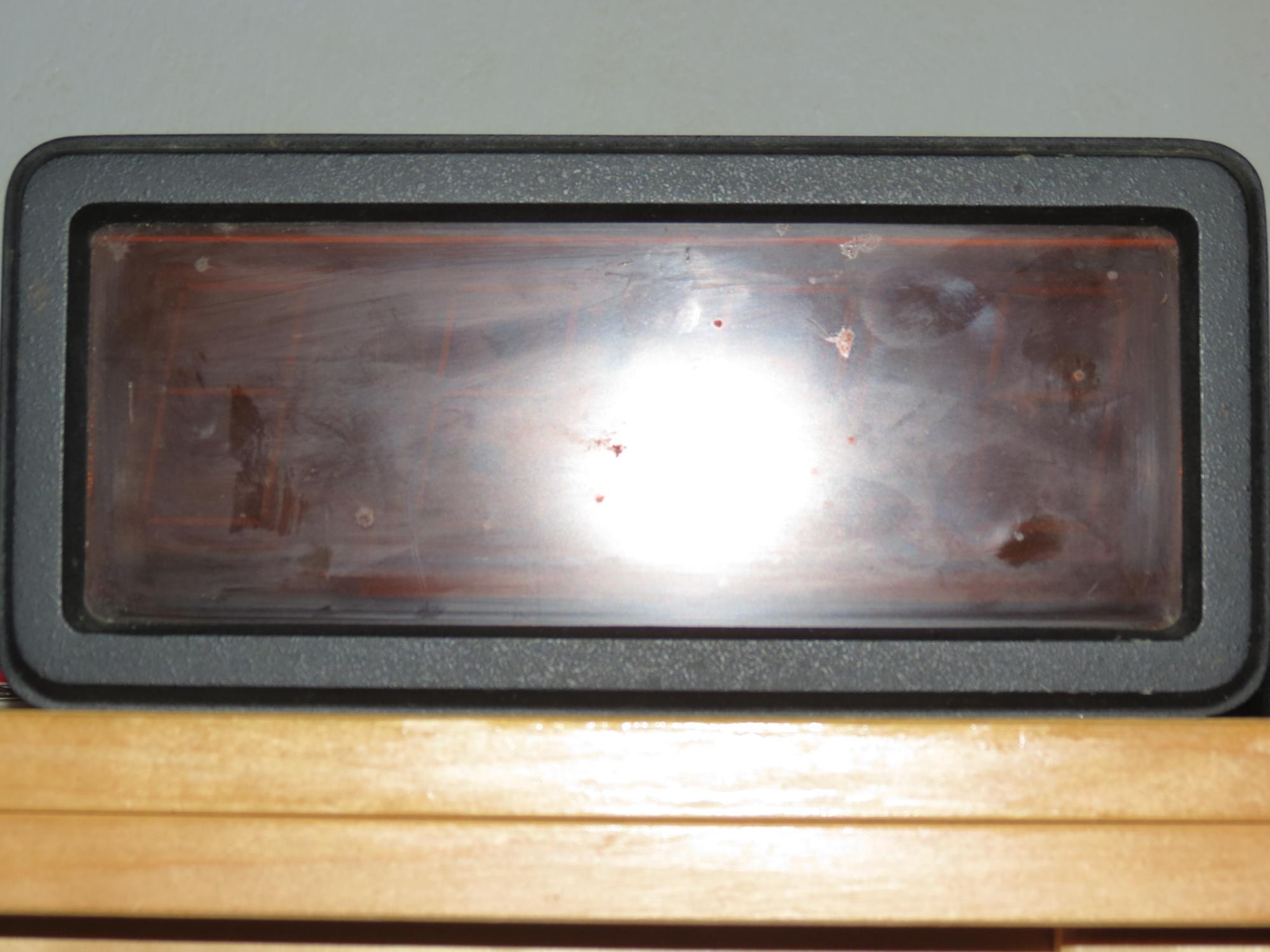
Not very interesting but good contrast perspex. Here's the back of it:
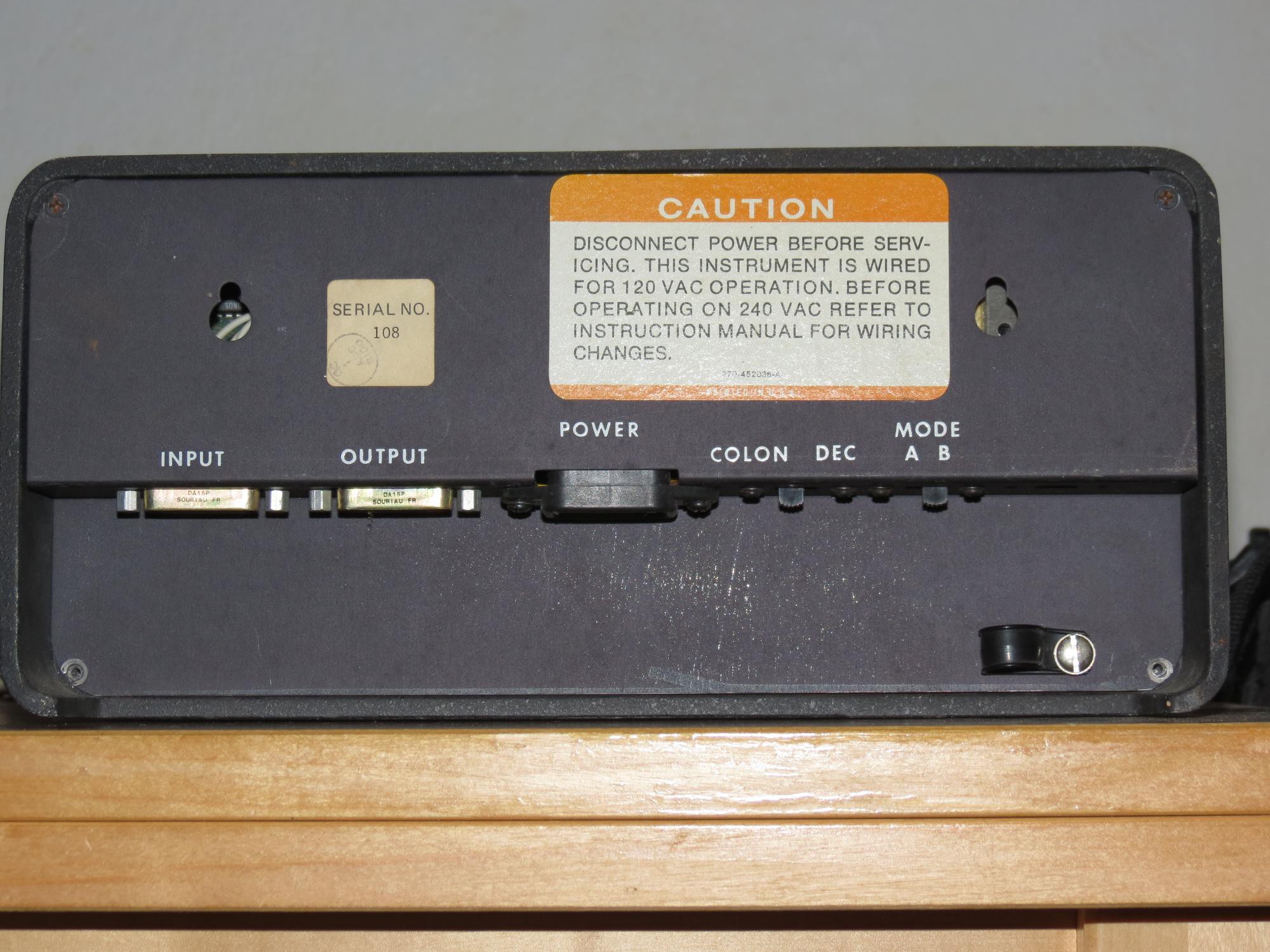
This gave the first hint that it wasn't a conventional digital clock. The input and output connectors suggested that it was meant to run in a clock network.
Opening the clock revealed this:
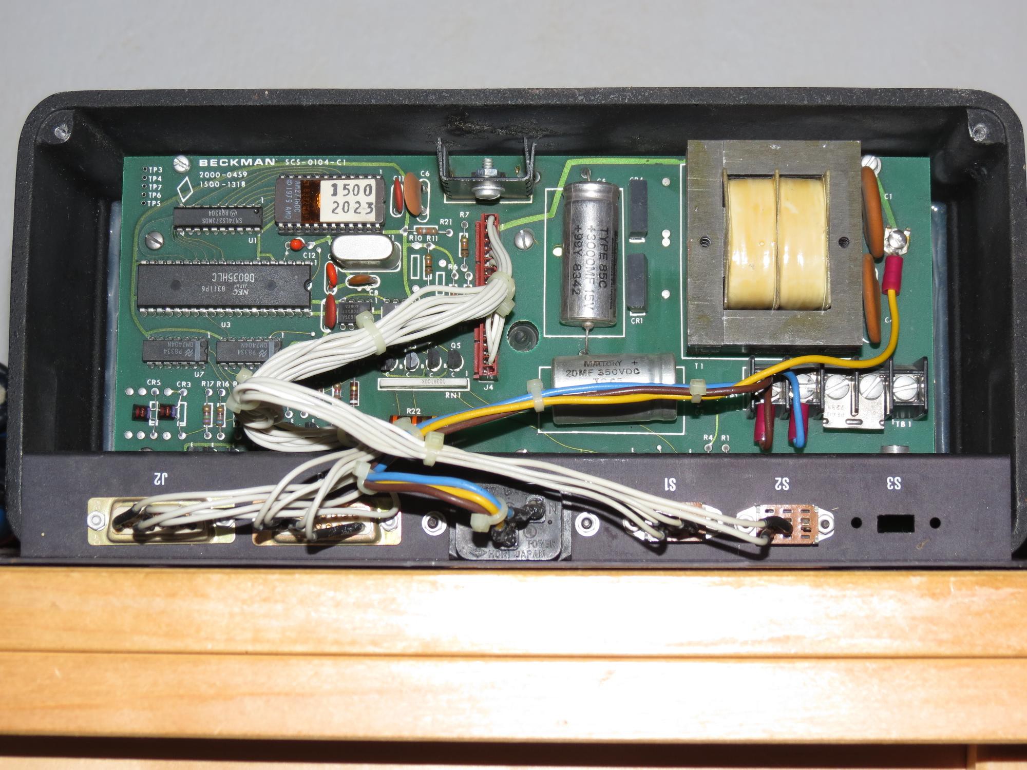
The transformer provides 5V for the microcontroller via a rectifier capacitor circuit feeding a heatsinked regulator. A separate winding is rectified and filtered to provide the HV for the neon display. The primary of the transformer has two windings which can be jumpered in parallel or in series for 120V or 240V operation. The microcontroller is an 8035, which is essentially an 8048 without ROM. It is driven at 3.579545 MHz. The program memory is in the socketed 2716 chip. The driver transistors are the MPSA42 for the cathodes, and a MPSA42 coupled with a MPSA92 for the anodes. More on this later.
Turning it on got a blinking colon, then after a minute or two, the display would show 00:02. My guess is that on failing to acquire a synchronisation signal it went into free-running mode. The clock gradually lost time.
Beckman is a manufacturer of the Panaplex displays. Enquiries about the provenance of the clock on Usenet (ye olde days) drew a blank. Even now I can find no data about the display panel. My best guess is that the panel was specifically made for this line of clocks, intended to be sold both in the US and international markets.
In the 1990s I acquired an EPROM programmer driven by a PC running DOS. With that I was able to dump the contents of the EPROM with the idea of disassembling the code and working out how to feed it the serial signals it wanted. However reverse engineering machine code is for masochists or people who have to pick apart computer viruses, so I gave that up.
And so matters stood until earlier this year, when I had more time on my hands and decided that the display was too good to leave idle and I should try to made a conventional digital clock out of it by either (1) replacing the 8035 with a modern microcontroller, or (2) writing code and burning a replacement EPROM. The latter course of action required less hardware modifications so I decided to try this first. Thus was born this restoration project.
Stage 1
While casting around for things to make with my ancient 8048 family chips, I came across the 8048 Assembly Code Tomb by Steven Bjork. There was a project for an 8048 digital clock using a MC146818 real time clock chip. I have quite a few of these, extracted from old PCs, and also some of the DS1287 variant which combines a lithium cell. There were instructions on the Internet for using an external cell if the internal one had gone flat.
However on some pondering, I decided to not include an RTC but use the mains frequency for timekeeping, like consumer digital alarm clocks, because I wouldn't have to modify the circuit to interface the DS1287. The task of reinitialising the time on power cycle won't happen often.
So the design goals were:
- Display hours and minutes (duh) and blink the colon at 1 Hz
- Use the mains frequency as a timing source
- Have two buttons to set the hours and minutes
- Minimal modification of the existing circuitry
- Produce firmware for a replacement EPROM in the socket
I knew that I could use the multiplexed display driver circuitry as is. All I had to find out was the mapping of the anodes and cathodes to the 8048 ports.
Some circuit tracing with a continuity meter showed that the anodes were driven by the upper nybble of port 2, and the cathodes from port 1. A 1 level on a port 1 pin turned on the cathode transistor. For the anode drive, I found that the circuit was this:
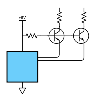
Very clever, the MPSA42 is in common base configuration and the port 2 pin pulls down the emitter to make the transistor conduct and turn on the MPSA92 on the high side. Essentially the MPSA42 is running as a level shifter. So to turn on the anode, the pin should go to 0.
For the software toolchain, I found the ASM48 cross-assembler and the ASXXXX family of cross-assemblers. I use both and compare the binaries generated which gives me high confidence that there are no assembler code generation errors. I found the S48 simulator by William Luitje. There is no website for this but you will find it archived on many places on the Internet. I installed this on FreeDOS in a virtual machine under VirtualBox. I could not have completed this project without S48, it allowed me to test the code by observing the state of the machine.
Coming back to the display logic, I didn't know the mapping of the port 1 pins to the 8 cathode segments or the port 2 pins to the anodes since I had no data on the display panel. I took the existing EPROM code and traced its execution in the simulator until the instruction that mapped from a digit to a seven segment pattern was hit. I knew that this would be either a MOVP or a MOVP3 instruction. From there I found the location of the lookup table. It turned out the correspondence of segments and port 1 bits was this:
76543210
:abcdefg
For the anodes I decided to just try one scan order and if that was wrong, to reverse it.
Code structure
Now the structure of the code. I decided I would use the internal timer to generate the tick, the interval at which the display is scanned, and actions taken on switches. The timer interrupt would switch to the next digit, turning on the appropriate cathodes for that anode. Outside of the interrupt routine, a busy loop would wait on the timer overflow flag and through a couple of software counters, dividing to 50 Hz, then 1 Hz, advance the seconds counter and ripple through to minutes and hours as necessary. In addition it would check the switches and with appropriate debouncing and delays, increment the minutes or hours to set the time.
I chose a tick period of about 3.3 ms which means the digits are refreshed at about 75 Hz, fast enough to not flicker. I also gather that these Panaplex displays have a keep-alive cathode for rapid switch on. It seemed that ghosting, which is a problem with multiplexed nixies wasn't likely to happen.
Testing
After mangling Steven Bjork's code way out of shape, I got something that I was willing to burn to an EPROM. At this point I encountered issues with the EPROMs of this era, blogged here. Fortunately I was able to use a 2816 EEPROM which also sped up my experimentation cycle.
I plugged in my EEPROM and turned on the clock with trepidation, ready to turn it off quickly. My main worry was that I would pump too much current through the display by failing to multiplex it correctly. Although watching the port outputs in the simulator had given me some degree of assurance.
The initial time at boot up is 12:34 and at the moment of truth, the display showed 43 21. So I was multiplexing it correctly but had the digits reversed. A quick edit and burn with the EPROM programmer, and I got the correct order. It was also advancing, and I took this picture a few minutes later:
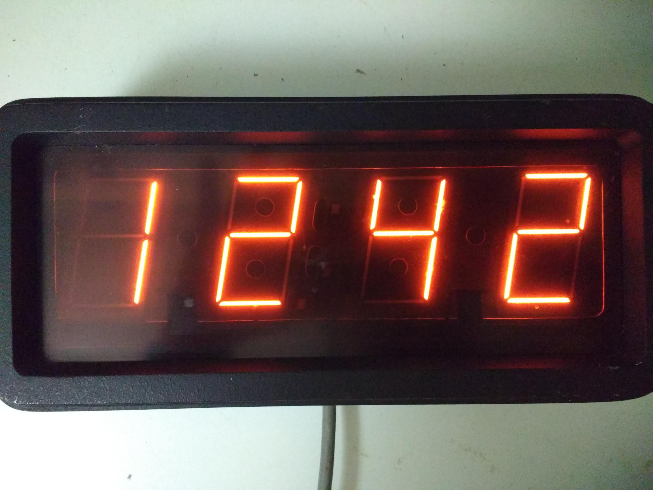
No sign of any ghosting.
Unfortunately the time was advancing at only half speed. Before I could investigate that, the display winked out. Blast, had I blown up the hardware? No sign of smoke. Plugging in the old EPROM gave the expected behaviour. So I put it down to bits in the EEPROM flipping randomly possibly due to inadequate programming causing the program to become garbage. I went through my counter divisor calculations again, found the error, reburnt the EEPROM and got it to advance at roughly the correct rate.
As the counter divisors do not divide the crystal frequency exactly to give 1 Hz, the clock loses a few minutes a day. That's alright, this will be fixed when I provide the 50 Hz reference frequency in stage 2.
Stage 2
I spent some time tracing the circuit of the clock with a continuity meter and I found out these things:
- The A/B switch at the back is wired to the T0 pin. A closes the switch. So this was used to select between two options in the old firmware. This meant that after disconnecting the switch I can use T0 for one of my settings buttons.
- The DEC/COLON switch at the back routes pin port 1.7 to one of two transistors, which would be the ones driving the decimal point and the colon respectively. Since the decimal point is nearest the hours digit, this means that the anode of the colon is that of the hours digit, so I edited the firmware for this.
- The T1 pin is connected to one output of the 9637 dual RS-422 receiver chip, and this is how the old firmware received serial data. This meant I would have to cut the trace to the pin to use it as the other settings button.
- Disassembling the old firmware revealed some EN I (enable interrrupt pin) instructions. This meant that the I pin was connected to something and I would have to cut the trace to the pin to use it as my 50 Hz square wave input.
Armed with this knowledge I found a logical error in my firmware and now I have the colon blinking at 1 Hz.
Now I needed a circuit to produce 50 Hz timing reference. What I designed was this:
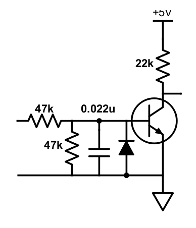
The input is taken from the secondary winding of the transformer before the full-wave rectifier, smoothing capacitor and voltage regulator. It is a half-sine wave at 50 Hz with a peak amplitude of 12V. (The transformer is overspecified since this rectifies to about 13V DC and only 5V is needed by the microcontroller, so the regulator dissipates the difference as heat.) Thevenin's theorem tells us that the resistors and capacitor are equivalent to a RC low pass filter of 23.5 kΩ and 0.022 μF which has a -3 dB point at about 300 Hz, to filter out noise. In addition the I input is polled about 300 times per second and this also reduces the probability of registering noise. The reverse polarity diode is redundant since the negative excursion is clipped to about -0.7 V by the full-wave rectifier, but is useful in case you encounter a center-tapped transformer winding in which case a full sine wave is delivered. Any small signal transistor will do, it only needs a moderate gain over 20.
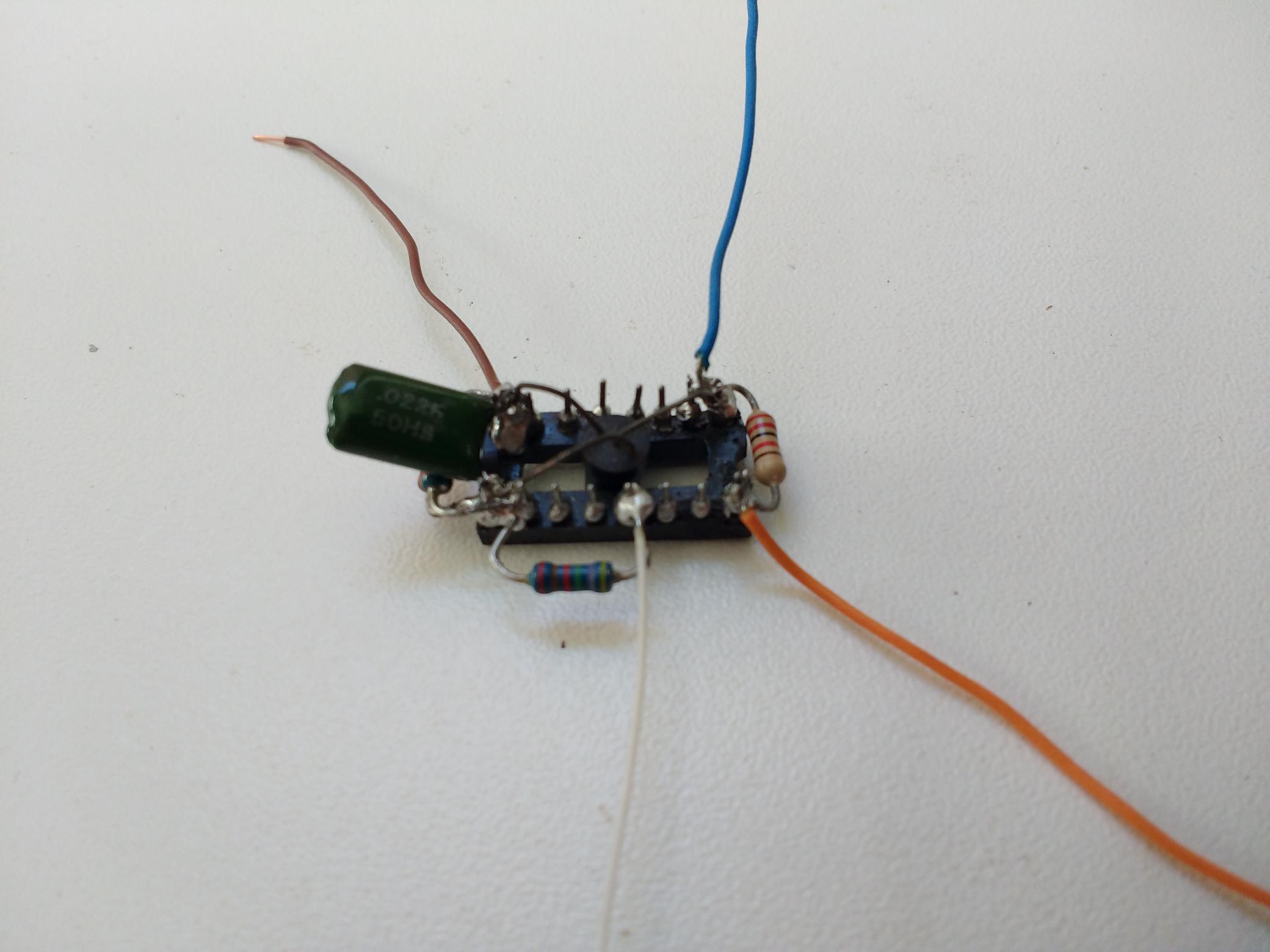
I didn't want to use a small circuit board to mount the components on. I decided to use a IC socket to hold the circuit. It was a socket that had been warped when scavenging components from a PCB with a heat gun so I was putting waste to use. ☺️ Here is the assembled circuit.
Before I added the circuit I had to prepare the main board by using a craft knife to cut the traces to the pins that were connected elsewhere. The T0 pin is no longer connected without the A/B switch. The T1 and I pins were both connected to the RS-422 line driver IC and had to be disconnected.
Here is the circuit, mounted piggyback on the microcontroller and wired in. The power is drawn from the +5 V and ground pins of the microcontroller. The output of the circuit goes to pin 6. Care had to be taken not to short adjacent pins. You will also notice comparing with the photo above that I have removed the wiring loom, connectors and switches for the old functionality as they are not needed and just get in the way.

So time for another moment of truth. I edited the code to not freerun the clock but use the frequency input, programmed the EEPROM and put it into the socket.
Colon blinks at 1 Hz and the clock seems to advance as expected. Success!
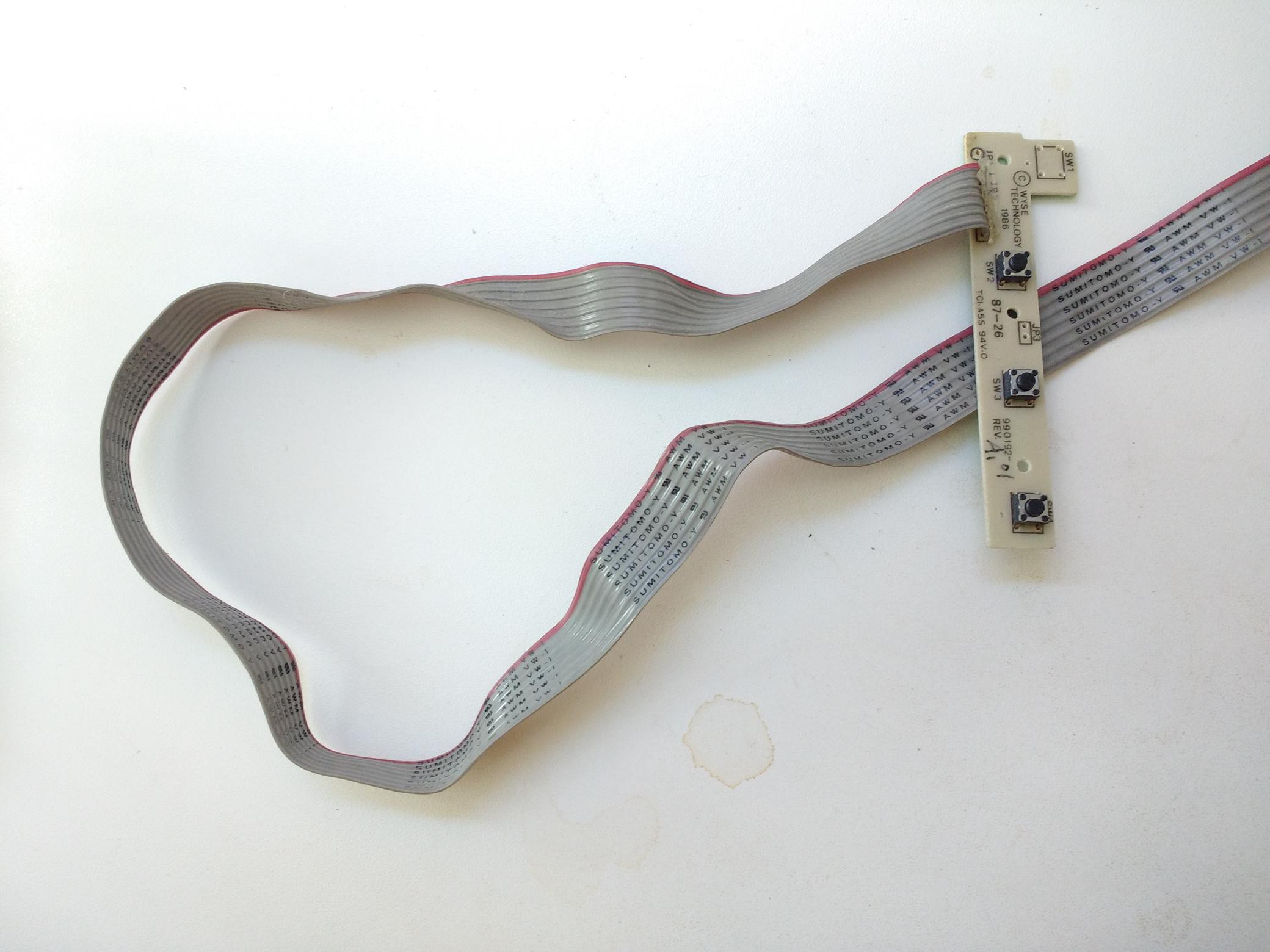
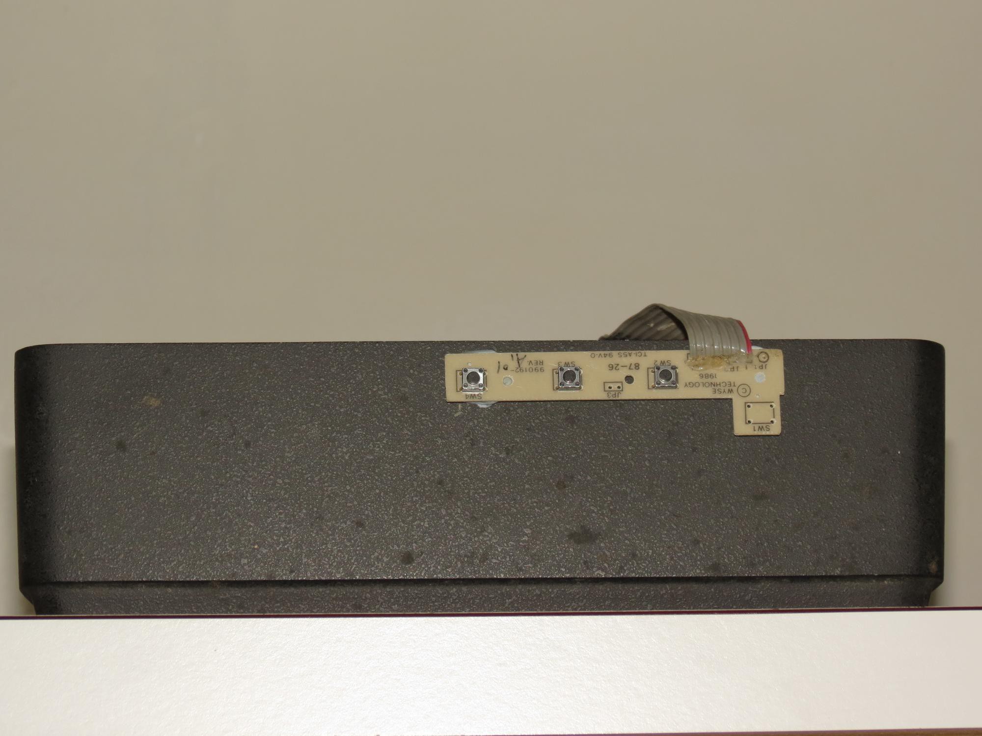
For the switches, I found a ribbon cable and switch array in my junk box that I had stripped out of a defunct laser printer ages ago, shown below. It happens to be about the same vintage as the clock if you look at the year on it, hahaha. I'm sure you have something similar. I mean, doesn't everybody have such things in their junk box? ☺️
I wired this up to the T0 and T1 pins of the microcontroller, reassembled the software with the switch handling code enabled, plugged in the EEPROM and switched on the clock. My main concern at this stage was whether the switch logic was correct and whether the debounce, delay and repeat periods were suitable. But it all worked like a charm, I could advance the hours with one button, and if I held it down it would autorepeat at 4 times per second, and similarly for the minutes with the other button. All thanks to being able to simulate the software in the emulator before committing to EEPROM.
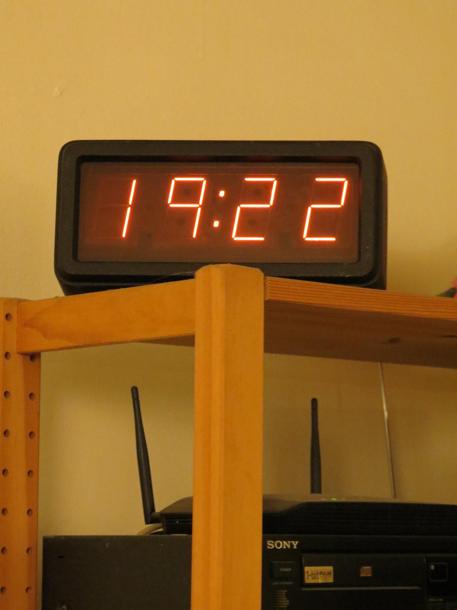
High five to myself! Here are the switches stuck to the top of the clock with Blu Tack.
And here is the clock on top of my entertainment rack.
Code notes
In the 8048 family, the inputs I (when interrupt not active), T0, and T1 are level sensing. For example, if a button is closed, the level will be reported by the test instruction throughout the duration of the closure. Thus the software must know if this is the first time the level changed and if so store the changed state, in effect detect the edge. You will see this logic in several places in the code.
Although the clock displays only HH:MM, it does store the seconds. Because the code zeros the seconds whenever the minutes are set by button, to synchronise the clock, set the hours and minutes, then wait for the minute to tick over and click on the minute button once more to advance the minutes counter and zero the seconds counter. This is a useful code feature for other digital clocks.
Following the suggestion of a friend, I've implemented a "power fail" feature. The colon blinks 3/4 on instead of 1/2 on when powered up and before any buttons are pressed. It won't be needed much, power is reliable here and it will usually be obvious when the power has been interrupted, but it only took a few additional lines of code to add.
An offer
If you managed to read this far, then you may have noted that I was not able to program the 2716 EPROMs in my junk box as my programmer doesn't go up to 25V. If you are able to use my 24 pin EPROMs, you can have the 6, but you should
- really need them and can't use any of the workarounds mentioned in my blog post
- pay for postage (might cost more than sourcing it elsewhere)
There are 2x2716, 2x2516 (=2716), and 2x2532 (!=2732) EPROMs. Contact me if you want them. I will be using 28 pin and above EPROMs in future projects.
Epilogue
I can hardly believe that after 30+ years, I've finally completed this project. That was satisfying. It must be a record of sorts. Over those years, I've completed graduate school, started work, changed jobs and moved home several times, lost touch with friends, made new friends, reconnected with old friends, lost family members and friends, gained new knowledge (and hopefully some wisdom and equanimity). And of course technology and the world kept moving. All that time, the clock patiently waited for this day. I should award myself a medal that reads "This time, I finished it". ☺️