Close
0%
0%

Blink an LED to your Heart Rate

Detect your pulse using Computer Vision and flash an LED at the same rate

Similar projects worth following
2.9k views
0 followers
This is another entry to the "Blink an LED" MacroFab Design Contest. While brainstorming for ideas, I thought it would be interesting to blink an LED based on human movement. I originally planned on using a Microsoft Kinect as the input device, but instead found a project where the Kinect determines the pulse of the person it's looking at. Later I found out that there's nothing special about the Kinect for this application and it can be performed using a normal webcam. I lightly modified an application I found on GitHub so it sends the detected heart rate over serial. I'm using a Digistump Digispark development board (which unfortunately can't be bought on Mouser) as the serial receiver and LED blinker, but nearly any development board that can talk over serial and has an LED will work.

This is the original project I found for detecting pulse rate using a Kinect.

Afterwards, I found this Python webcam pulse detector.

I forked that project to here: https://github.com/dwaq/webcam-pulse-detector to make my own modifications.  

  1. I uncommented the Serial calls and documented how they worked in the README
  2. I changed the format that the data is sent over serial. It was sent as a string, but I sent it as a one-byte integer to make it easier on the receiving microcontroller.
  3. I added a delay between each serial message so it would not overwhelm the Digispark's virtual comm port. I tried to make this work with threading, but I didn't understand why it wasn't working. So instead I added a simple (hacky) counter that works to delay the message 25x slower than normal. I can think of two ways to improve this:
    1. use a microcontroller with a hardware-based serial port may be able to handle the unrelenting rate of the messages
    2. Use the hardware PWM to set the LED timing. I'm using delays because there wasn't an easy way to adjust the frequency of the Arduino library's analogWrite()

This is the process on the microcontroller side:

  1. Read the pulse sent over the serial as a BPM (beats per minute) pulse
  2. Convert that to beats per second
  3. Invert that to determine the period of a beat
  4. Set the on time of the LED to 3/8 of a beat
  5. Set the off time of the LED to 5/8 of a beat
  6. Set the LED high
  7. Delay for the on time
  8. Set the LED low
  9. Delay for the off time
  10. And repeat...

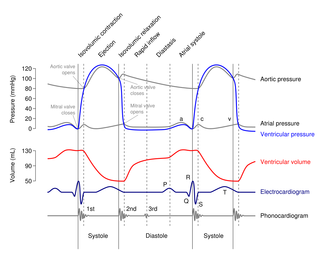
According to Wikipedia, for a typical heart rate of 75 BPM, the cycle requires 0.3 sec in ventricular systole and 0.5 sec in diastole. I asked my wife (who is a nurse) and did research online and could not determine if systole is always 0.3 sec, or always 3/8 of the pulse. I assumed that it's always the same proportion of the pulse, so I chose 3/8 of the period for light on and 5/8 of the period for light off. If anyone knows, I would love to make this blinking more realistic and update the project accordingly.

This is another interesting project on Hackaday that does something similar to this project using only hardware.

  • 1
    Install software for PC application
    1. Install Python 2.7 including pip package manager
    2. Use pip to install OpenCV, Numpy, and serial with:
    3. pip install opencv-python matplotlib serial
    4.  Clone or download my project from: https://github.com/dwaq/webcam-pulse-detector
  • 2
    Install tools for microcontroller

    This step will change depending on the microcontroller that you use, but for the Digispark, follow the instructions here: (BTW, the Tomu looks like a modern replacement to the Digispark)

    http://digistump.com/wiki/digispark/tutorials/connecting

    After installing the board in the Arduino IDE, a warning will be displayed in the Arduino console with the location of the drivers. Move to this directory and install the drivers manually. Use the drivers linked in this forum post if you're using Windows 10.

    Copy this code into a new Arduino project and flash it to the Digispark (note that you hit upload and then insert the Digispark into the USB port when prompted):

    #include <DigiCDC.h>
    
    // onboard LED pin
    //#define LED 1
    
    // RGB Shield Red LED pin
    #define LED 0
    
    void setup()
    {
      // begin serial    
      SerialUSB.begin();
    
      // set LED as output
      pinMode(LED, OUTPUT);
    }
    
    void loop()
    {
      if (SerialUSB.available())
      {
        // read the pulse (in beats per minute) sent over serial
        float pulse_BPM = SerialUSB.read();
    
        // convert pulse to beats per second
        float pulse_BPS = pulse_BPM/60;
    
        // calculate the period of one beat
        float period = 1/pulse_BPS;
    
        // calculate floating point value of the time where the light should be on
        // assuming the systole lasts 3/8 of a pulse period
        float time_on_f = 0.375 * period;
    
        // convert that time on to an int in milliseconds
        int time_on = time_on_f * 1000;
    
        // calculate the remaining floating point time in the period - "the diastole"
        float time_off_f = period - time_on_f;
    
        // convert the time off to an int in milliseconds
        int time_off = time_off_f * 1000;
    
        // set LED high
        digitalWrite(LED, HIGH);
    
        // delay for the on time
        SerialUSB.delay(time_on);
    
        // set LED low
        digitalWrite(LED, LOW);
    
        // delay for the off time
        SerialUSB.delay(time_off);
      }  
    
      // need to call a SerialUSB function at least every 10ms
      SerialUSB.refresh();
    }

    After the device is programmed, make note of the serial port that shows up for the communications. It's different than the port that was used to program it and the new port will be needed for the next step.

  • 3
    Start the PC application

    Open a terminal at the location of the project from step 1.4. Use the following command to start in serial mode (ensure you change the COM number to the one you found in step 2.

    python get_pulse.py --serial COM5

    The PC application will start your webcam. Aim the square at your forehead and press the "s" key. Your heart rate will be determined and the LED on the microcontroller will start to blink. Congrats, you're done!

View all 3 instructions

Enjoy this project?

Share

Discussions

lixovo1853 wrote 02/08/2023 at 22:39 point

Is it possible to put the link of the used sensor that contains a light?

  Are you sure? yes | no

Darian Lewis wrote 09/11/2018 at 00:18 point

The QT interval is not constant.  It depends on age, gender, heart rate, and other factors (balance of Na, K).  Normally, the QT interval is 0.36 to 0.44 seconds (9-11 boxes).

  Are you sure? yes | no

Dillon Nichols wrote 09/11/2018 at 00:24 point

Thanks Darian! That's good to know. 

  Are you sure? yes | no

Similar Projects

Does this project spark your interest?

Become a member to follow this project and never miss any updates