 jackw01
Controller
Almost any 8-bit AVR controller is suitable. I used an Adafruit Pro Trinket since I had one lying around, but any ATmega328 or ATmega32U4 based Arduino Pro Mini, Arduino Nano, Teensy, Adafruit ItsyBitsy, or Adafruit Metro Mini would work too.
Power
For clocks with 24 or fewer LEDs, a USB power supply is sufficient. Larger clocks will need a high-current 5V power supply with appropriate wiring to the LED strip. Assume a peak current draw of 60ma per LED.
RTC
The clock uses a DS1307 RTC connected over I2C as breakout boards are widely available and cheap.
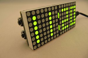
LEDs
Any size ring of LEDs should work but only 24 has been tested. Adafruit seems to be the best source of suitable WS2812B rings. The data input to the LED chain is connected to Arduino Pin 3.
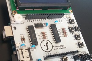
User Interface
To stay simple, the only user interface is a tactile pushbutton that pulls Arduino Pin 4 to ground and a potentiometer for adjusting brightness connected to Arduino Analog Pin 0.
3D Printing
The enclosure for an Adafruit 24 NeoPixel ring is 3D printed in three parts and the STL files and Fusion 360 archive are available at Thingiverse: https://www.thingiverse.com/thing:2730265
Firmware
The clock's firmware is written in C using the Arduino format and standard library so it can be built and deployed with the Arduino IDE. FastLED is used for controlling the LEDs because of its built-in HSV to RGB conversions and temporal dithering which allows higher color resolution when the brightness is low.
Instead of lighting the nearest LED to each hand position, anti-aliasing is used for a smooth and organic looking animation. Additive and alpha blending are used in combination with the anti-aliasing so that the "hands" blend fluidly when they pass over each other.
All constants and color scheme data are in a separate header file for easy tweaking.
The firmware is available at Github: https://github.com/jackw01/led-ring-clock
 jsc
jsc
 danjhamer
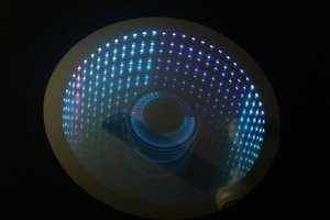
 Dushyant Ahuja