Kelly Heaton
-
A sweeping overview of work to-date
09/24/2018 at 20:46 • 0 commentsI've been building analog electronic circuits to generate the sounds of nature for about a decade, and I have some finished artworks to show for it. My first project log is an overview of my work to-date and is intended to give you a sense of what this project is all about. In future logs, I will dig into the details of how to build many of the circuits that you see (and hear) here.
In my earliest works to generate electronic sounds, I did not use perfboard or printed circuit boards. Instead, I punched holes into paper or canvas using a dental tool, inserted through-hole components, and soldered them together in a freeform way. This worked just fine, but it's hell to fix problems if they arise. Here's video of some panels I made to frame a piece called "Night Tree," 2012
Note that early in my practice, I was not making my own speakers. I relied heavily on piezo buzzers from RadioShack, which are now hard to find... but more on that in a later project entry.
In a related work, "Summer Insects" (2012), I explored the buzzy sounds that cicadas make on a hot day in Virginia. I'm including video of this piece to give you a feeling for the acoustic variation that can be achieved with the same basic circuit designs.
To see other electronic works from this time period, please refer to my project "The Parallel Series" (2012).
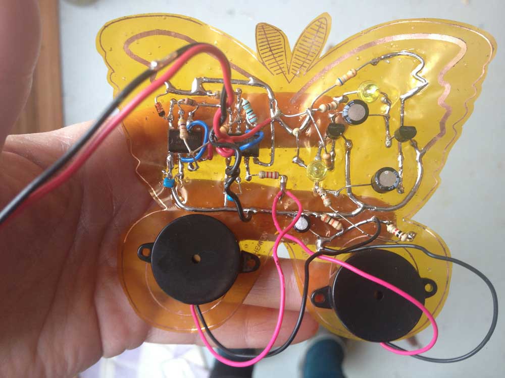
In 2013, I made my first foray into printed circuit board design and built a sculpture called "Electrolier (Summer Night)," 2013. The electronics are soldered on flexible printed circuit boards that I designed and etched myself using ferric chloride. While the circuits sound like tree crickets, I designed my boards to look like moths and tree leaves. The sculpture is an arboreal night scene under the moon and starry sky.
![]()
While these works were well-received, I was frustrated that hardly anyone seemed to understand my use of analog electronics to generate natural sounds. Most people assumed that I recorded the audio, and when I tried to explain otherwise, I got blank stares. I got many more questions about whether the electronics would break and how I proposed to handle this problem --which overwhelmed me with anxiety, since my early freeform circuits are pretty much guaranteed to "die," just like living organisms. So, for several years, I stopped making electronics about nature and focused instead on paintings and sculptures about electronics and nature. These projects are documented on my website: Pollination (2015), Anthropocene (2015-17), and The Human Electric (2015-ongoing).
Death, ignorance and anxiety be damned, an artist must make her work. In early 2018, I started building circuits again and I'm working on several new "electrolier" sculptures. Because my larger artworks are complex and time-consuming, I like to make small, painterly studies of my animal circuits to compliment the longer development process. These studies help me to mentally connect a circuit to its natural subject, so I figure it will help others to do the same. Some recent examples include Unafraid Field Cricket (2018), Gray(fish) Tree Frog (2018), Bluebird with Cricket (2018) and Hawk Got Its Own Cry (2018).
In my upcoming project logs, I will show you how I build some of these elements starting with how to make your own piezo electric speaker.
-
Speaker design for nature's musicians
09/25/2018 at 02:26 • 0 commentsThe chorus of nature sounds that I generate relies on multiple low-cost speakers that I can distribute in space. Given my project goals, it makes no sense for me to use an audio mixer and a couple of Hi-Fi speakers --every one of my animal circuits has its own means to make noise, just like creatures do in nature. Sometimes, if I want to create a sound that is static-y or muffled, I will use a cheap 8 ohm speaker. But for the most part, I have found that piezo electric buzzers work best. Piezo disks can produce a clear, jingle-like timbre that is perfect for many types of crickets, tree frogs, bats, and birds.
I used piezo buzzers from RadioShack for at least a decade, notably parts #273-059 and #273-060, as their sound character is excellent for my application. However, these buzzers became hard to get when RadioShack went out of business and I sought a substitute part. After buying a few that I didn't like, I decided to reverse engineer the RadioShack buzzers and that turned out to be a blessing in disguise. Physical speaker design is a great way to affect electronic sound. In the following video, you can see me playing with the physical properties of a 2.8 KHz piezo with feedback.
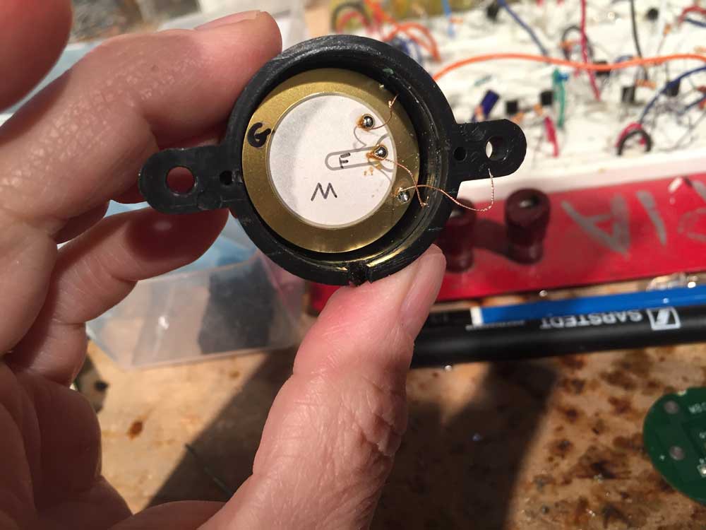
Reverse engineering is a great teacher. First of all, I discovered that not all piezo disks are made equal. Some piezo elements have only two contacts and are best suited for electrical pick-up, like listening to faint sounds. I don't use those. The kind I use (and RadioShack) is a piezo element with feedback, which has three contacts: M (main), F (feedback), and G (ground).
![]()
Piezo disk elements have different resonances, so you need to get the right one for your sound. RadioShack buzzers are in the 2.8 - 3.6 Hz range. Digikey sells a variety of piezo elements with feedback in the 2.8 - 2.9 KHz range, for example. You can also find them on eBay or Alibaba.
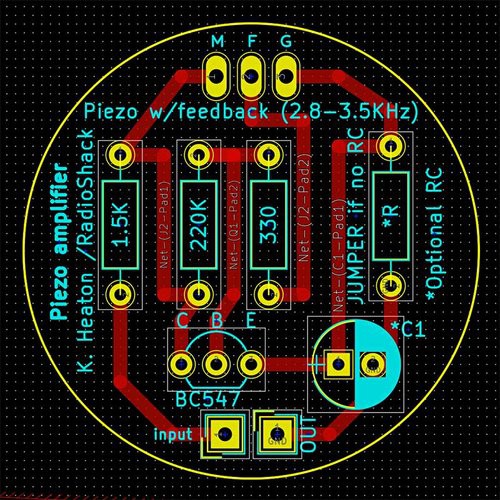
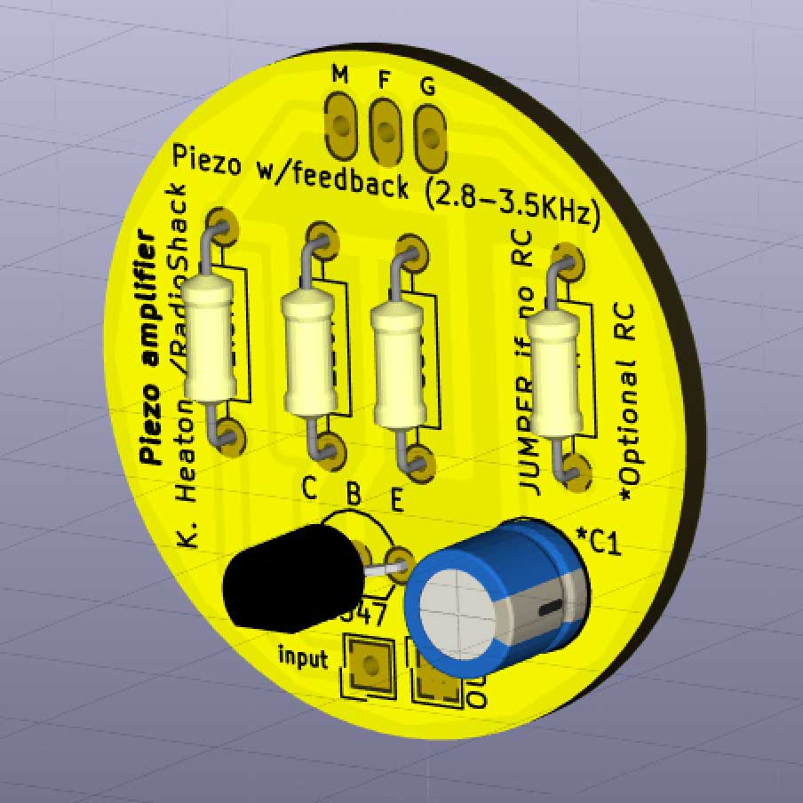
Next, you need an amplifier for the piezo element. RadioShack buzzers include an internal amplifier circuit and I reverse engineered their design to make my own board. In my layout, all of the components are through-hole and the reverse side is a ground plane. Under my project files, you can find an image of my circuit schematic with descriptive annotations. I have provided a zipped folder of my Gerber files ("Piezo_amplifier2") that you can send out to a board manufacturer and have some of these made. I'm partial to PCBWay.
![]()
![]()
Once you've got your piezo element in hand and you have a way to amplify the sound (my circuit "Piezo_amplifier2" works for this), then you need a speaker housing. In a pinch, you can fashion something out of cardboard and tape.
I like to make my speaker housings with a vacuum former and laser cutter at my local MakerSpace, Nova Labs in Reston, VA. To do this, I first made a buck for the thermoformer out of laser cut rings that I stacked and glued in a pyramidal shape. Then I form .080" - .090" acrylic over the buck -- which requires some experimentation to get your settings right because acrylic wants to "bounce back" when you try to shape it. Use mold release! Finally, I laser cut the thermoformed shapes out of the vacuum formed acrylic sheet, also adding a hole in the middle for the sound to emerge. I cut round disk backings with holes for my wires. Hopefully the following video will clarify, and please also visit my blog for photos of the process to make the housing.
Notice how adjustments to the housing and pressure on the piezo element modify the sound.
I'm always on the lookout for new speaker designs, so please message me if you have ideas to share!
-
Crickets: nature's favorite astable multivibrator
09/25/2018 at 15:42 • 0 commentsWhat rural soundscape would be complete without crickets?
What is it like to be a cricket?
It's one thing to listen to their rhythmic chirping, but imagine spending your life singing the same tune indefinitely, changing tempo in response to heat, and only shutting up when you're afraid of imminent death. Wait, how is that different from human thought chatter? I digress.
Crickets are an excellent way to explore the basic, fundamental building blocks of electronic music: oscillators. Specifically, crickets taught me about astable multivibrators -- a term which, for those uninitiated in EE lingo, is probably the last thing you would search in your quest for "how to build an electronic cricket."
An astable multivibrator is a circuit that bounces back and forth between two states (and will do so indefinitely until you disconnect power). It's like a perfect Pong volley -- and therein lies its great strength and weakness. You can use an astable multivibrator to generate a consistently oscillating waveform. This gets acoustically (or visually) boring after awhile and in later logs I will show you how to introduce randomness. But for now, I will focus on my design of boing-but-educational crickets.
My simplest circuit for a chirping cricket is comprised of two astable multivibrators made with discrete transistors: one controls the chirp timbre and the other controls the chirp tempo. For your reference, I uploaded a schematic called "Heaton_transistor cricket.jpg" that you can find in my project files section of this site.
To understand how the circuit works, it helps to look at a single astable multivibrator wired with LEDs. Check out my video "Transistor astable multivibrator" in which I change the capacitor values in a single astable multivibrator. The first configuration is symmetrical, having two 100 uF electrolytic capacitors. Next, I replace one of these with a 22 uF capacitor and the pulse becomes obviously asymmetric. Last, I remove a 100 uF capacitor and replace it with 47 uF. The pulse remains asymmetric but is visibly different than before. This is a simple, low-cost way to achieve different oscillating patterns, aka tempo.
PS: Wow, my breadboard is dirty from 20 years of use/abuse.Next, let's look at how to make the quality of a cricket's "voice," or the chirp's timbre. For this, I use an astable multivibrator with smaller electrolytic capacitors, like 2.2 uF, causing the electricity to bounce back and forth fast enough that we perceive a texture instead of a pattern. In the beginning of my next video, "Simple discrete transistor cricket," you will hear a steady, unbroken ringing sound that is created by this circuit design. The resulting "timbre oscillation" (happening on the left side of my breadboard) goes through a simple high-pass filter and transistor amplifier (right side of my breadboard) to one of my custom 2.8KHz piezo electric speakers (seen in the background).
Next, I unplug a base resistor from one of the transistors in this astable multivibrator and you hear silence, because the timbre oscillation stops. I then reconnect the transistor's base to a signal incoming from another, slower astable multivibrator -- the tempo generator, shown when I pan left. Voila, the cricket starts to chirp. Finally, for extra credit, I add a pull-up resistor on the same transistor's base to show you how this simple change affects the sound. Minor adjustments to my design will give you many variations on the theme (==crickets with personality).
Happy chirping!
-
Percussive bugs: rattle, sizzle, resonance
09/29/2018 at 00:18 • 0 commentsIn the southeastern United States, the ring-tone chirping of crickets at night is accompanied by a percussive rattle that's common from mid-summer through fall. Where I live in northwestern Virginia, the dominant percussionist in our nighttime chorus is the Lesser Angle-wing Katydid. Similar to cicadas in timbre, but far less annoying, these bugs "shake their rattle" intermittently, calling once or twice and then going silent for five to fifteen seconds. Compared with a regularly chirping cricket, the delay adds complexity to an analog audio "Katydid circuit." You have to create the timbre and tempo of a rattle sound, and then you have to space out "packets" aka "envelopes" of this effect with silence in between --ideally randomized for natural effect.
In a first step, I built a machine gun circuit using a 555 timer. While the tempo is right, the timbre of a square wave is dull compared with a Katydid's sizzle and resonance. I reverted back to my cricket strategy and built two discrete transistor astable multivibrators, but that didn't work either because the simplicity of my cricket circuit depends heavily upon the acoustical properties of a 2.8 KHz piezo disk element. Katydids are resonant in a different frequency range than crickets. To make a long story short, I had to build a filter.
After some reflection on the sound quality of a Katydid, I decided that I needed a filter for "snare" or "high hat" as used in analog drum machines. Research led me to this very handy circuit by A. MAGIC PULSEWAVE:
![]()
With some minor adjustments (not needed for functionality--purely my preference), this circuit works perfectly to add sizzle, resonance, and noise to the output of an astable multivibrator. Note that I decided against a piezo disk element because --for a Katydid-- I prefer this little speaker (now obsolete but hopefully similar exist or I have more reverse engineering in my future). Here's a video clip to demonstrate the Katydid sound timbre. Notice the subtle complexity thanks to amplified noise from the abused bipolar transistor (gosh, horrible sentence out of context).
Since I'm on the topic of speakers and timbre, here's another video showing an overview of the circuit (including a second astable multivibrator for regular chirp) in which I demonstrate the Katydid's rattle through several different types of speakers. I end with a cool way to "play" a piezo disk in its housing. Electronic musicians: even if you find the earlier part of this video boring, check out the last 10 seconds for inspiration on how to physically manipulate the output of your synth to get a new electronic sounds.
Because I am piezo-obsessed, here's one more clip showing a bare piezo disk element as the output for this circuit (which provides sufficient amplification that my custom printed circuit board is not needed). I mess around with different connections to the feedback of the piezo (white wire), the last seeming to make a change -- a potential source of interesting effects that warrants further exploration. At the end of the clip, I show how the piezo sounds (differently) in different positions inside of a plastic housing.
In my next video, I show some of the cool effects that you can get by playing around with capacitors in an analog circuit. Be forewarned that you risk blowing one of your components (so careful if you don't have replacement parts). It amazes me how much one capacitor can change the behavior of a circuit -- and this fact extends to resistors and diodes as well. Especially note the weird chatter sound that I get about 1/2 way through this clip (start at 00:36).So what does this say about Katydids --the ease with which capacitance alters "their" sound in an analog electronic circuit? Of course, my entire approach to hacking nature's musicians could be a logical fallacy. Maybe analog electrical engineering tells us little or nothing about the inner workings of nature and I just *feel* like there's a comparison to be made. Oh well. There's no accounting for the compulsions of an artist. But seriously, all you entomologists out there, what do you think?
-
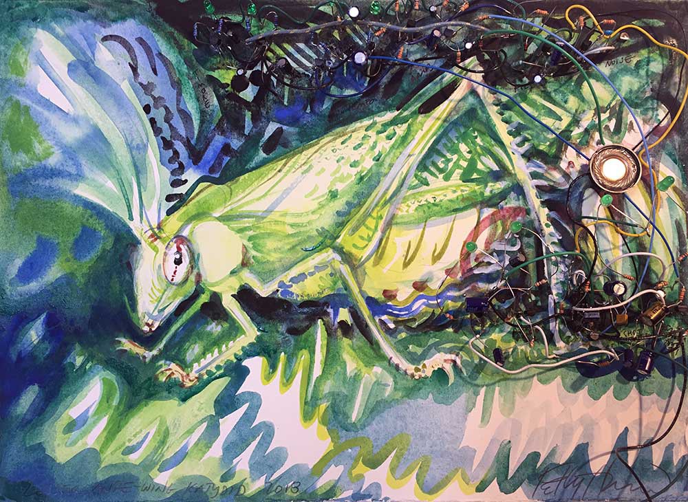
Lesser Angle-winged Katydid
10/02/2018 at 00:30 • 0 comments*This log is an extension of my last entry, so please start there if you want more information about how the following work of art was made.
![]()
I finished breadboarding my circuit for a Lesser Angle-winged Katydid. Then I forced myself to document it with a schematic -- "forced" because my tendency is to go on inventing things and forget my design history, and I have learned the hard way that I must solder an instance of my schematic to be sure that it's accurate. It's all good, though, because building a permanent circuit gives me a future reference to use alone or in parallel with other sound-generating circuits. Many of my circuits are sensitive to noise, so I try to test them in combination before I send out board designs or embark on a larger piece.
I got into the habit of making these electrified watercolor studies in the days before I used software for schematic design and printed circuit board layout. You can see images of early works here. As time goes by, these studies help me to remember why I designed the circuit in the first place, like a bookmark for a time and place in life. I realize that there are more practical ways to archive a circuit, but it's a good excuse to make art.
Here is a video of the Katydid "rattling." I included a couple of crickets to give the Katydid's sound a more natural context.
To conclude this log, it occurs to me that some of you might not have drawing or painting skills. While I can't teach you to be an artist, I can suggest this useful hack: project an image and trace it. Please refer to the instructions associated with this project for more details on "How to draw if you have no artistic talent."
-
Mother Nature Board (aka how to conduct a natural chorus)
10/05/2018 at 00:25 • 2 commentsThe question of how to conduct a chorus of nature's musicians is perplexing because humans aren't in charge --Mother Nature is. The idea of physically "playing" a cricket or other musical animal is compelling, but I'll leave that (cruelty-free) implementation to someone who knows how to play an instrument.
![]()
My approach is to let Mother Nature conduct her own, which is to say, allow a circuit to control an electronic chorus. What I want is an autonomous master sequencer that runs indefinitely, controlling the noise of multiple animal circuits in a seemingly random way, but never so abhorrent as to be unbelievable. My control circuit doesn't have to be truly random according to cryptologists, but it does need to be unpredictable for the average observer. Otherwise, listeners will detect a pattern and the effect will be unconvincing if not downright annoying.
The key to my solution is a circuit designed by Charles Platt called "Really, Really Random Number Generator" that was published in Make Magazine in May, 2015. Platt combines a white noise generator (a source of true randomness) with a Schmitt inverter and shift register to produce a never-ending sequence of random bits --eight bits, to be precise, as that is the output of the shift register in his design. I encourage you to read his article and study his schematic, as he does an excellent job of explaining the design principles and I am only standing on his shoulders (as in "standing on the shoulders of giants").
If you refer to my schematic "Mother Nature Board (random pulse gen).pdf" included in my project files, you will see that Platt's design makes up the lion's share of what I'm doing to simulate Mother Nature's timing. I made a few changes to his circuit because I am running at 12V instead of 18V, and I use a larger capacitor for the Schmitt oscillator because I want a slower clock for my shift register in order to see the state changes (plus, this is how I get so many bonus fireflies and other LED eye candy). The remainder of my schematic comprises two basic functions: logic gates to generate further random pulses, some of which occur less frequently than the states of the shift register; and a collection of 555 timers in monostable configuration, aka "one-shots" to generate pulses of longer duration.
Ultimately, it is the outputs of the one-shot timers that I want. These pulses are how I turn animal circuits on and off (or affect some other parameter). Platt's design is a starting point for me to control any number of animal circuits: an output of his random number generator (and logic gates, as desired) acts as a trigger for a one-shot. More frequent triggering equals more pulse out. The duration of a one-shot's pulse out is a factor of the resistor and capacitor on DIS and THR of the 555 timer. You have to breadboard the circuit and mess around with it until you get the frequency of triggers and pulse durations to your satisfaction. It's not hard, but I give you the following hints/ warnings:
-- The circuit is sensitive to noise.
-- Not all 2N3904 transistors are made the same, and you must get the right one for the noise generating part of Platt's circuit. I tested multiples from my collection and some worked, while others did not. If your shift register isn't shifting, it's probably a problem with the noise generator.
-- The trigger into the 555 monostable (one-shot) is active low. You can use leftover inverters in the hex Schmitt IC or build your own, as needed.
-- Careful about impedance. The logic ICs can't drive much of a load, so you might need to add a transistor switch in-between (especially when you want one output to control multiple things). This also applies to the output of the one-shots.
Last but not least, here is a video without sound that is intended to show the different elements of my Mother Nature Board. Pay attention to the LEDs: they reveal how the states are changing at various points in the circuit.
“The Earth has its music for those who will listen.” – George Santayana
-
A musical composition
10/05/2018 at 01:05 • 0 commentsWhile my project is far from over, I'd like to recap what I've covered thus far and offer you a little musical composition. As evidenced by this video, most of my circuit designs have yet to leave the breadboard -- that is work for the coming weeks (and months, as I layout many different artistic PCB designs for sculptural ecosystems). Still, you can see the following ideas that I've discussed in previous logs:
-- a variety of "animal circuits," aka analog electronic sound generators inspired by the nocturnal soundscape of rural Virginia
-- "Mother Nature Board," aka a discrete component random pulse generator for naturalistic sequencing of animal circuits
-- home-brewed piezo electric speakers, including some hacks like stuffing cotton into the speaker housing to muffle the sound
-- a painterly frog with a croaking circuit built in
I hope you've enjoyed my content thus far. Stay tuned for updates as I build a sculptural "electrolier" of the night in rural Virginia, as well as entirely new animal circuits based on my experience of the Mayan jungle. I've launched a GoFundMe campaign to finance electronic supplies for hacking nature's musicians in Akumal, Mexico. If you're interested to support me in this endeavor, please visit gofundme.com/hacking-nature039s-musicians-mexico Thanks so much!
-
One signal, many sounds
10/11/2018 at 20:39 • 0 commentsI've been migrating my circuits out of the breadboard and into soldered form. I'm also hooking up speakers so that my sound generating circuits are ready for installation in a sculpture of Virginia's nocturnal ecosystem. Because most of my circuits use a custom piezo electric speaker (built with my own amplifier board), I have to install each piezo element into a physical housing... and there's some interesting "play" here. One electronic signal can generate many different sounds depending upon the speaker's physical design. Here's a video of me testing various installations of a piezo element for an insect that makes a steady background noise.
It's cool to experiment with the interface between electrical signal and material properties. It's also critical to get it right, or else the piezo element will make a horrible rattling or screeching. Even a tiny drop of glue (to fix the piezo element in place) will alter the sound quality --usually the pitch-- and superglue can sound different from rubber cement or hot glue or tape. All of this is no news to a human musician, who knows that a note ill-played (even slightly) is a fail, and teensy subtleties often make the difference between average sound quality and genius.
It is interesting to wonder what makes animals of the same species sound different in nature: is it their electrical impulse or their physical form? (Is it their schematic, their CAD file, or their bill of materials?) Members of the same species inherit the same circuit design as well as physique. External physical factors, such as climate, have some degree of influence over material properties of the body --for example, a dehydrated cricket sounds differently than the same cricket wet with rain; a fat frog sings a different tune than the same frog skinny; and so on and so forth. We also know that "animal circuits" are sensitive to electromagnetic fields, and capacitive coupling undoubtedly affects individuals in close proximity. I suspect that physical factors play a greater role in the variability of an individual's song if but for no other reason because birds sound the same whether they are sitting on a tree branch or an electrical transformer (at least, I think they do). PS: Eventually I will tackle the challenge of bird song, but their vocal complexity requires more computation... which is why I have started with insects.
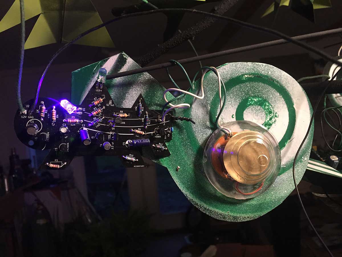
To end this log, I leave you with one more video clip of my "background noise" insect. Here it is with a plastic spool installed over the piezo (now painted green, black, and white). The soldered perfboard is embedded in a cardboard cutout that is painted to look like a forest creature sounds. Soon, this mixed media object will be joined with other embellished animal circuits to build a vignette of nocturnal musicians.
-
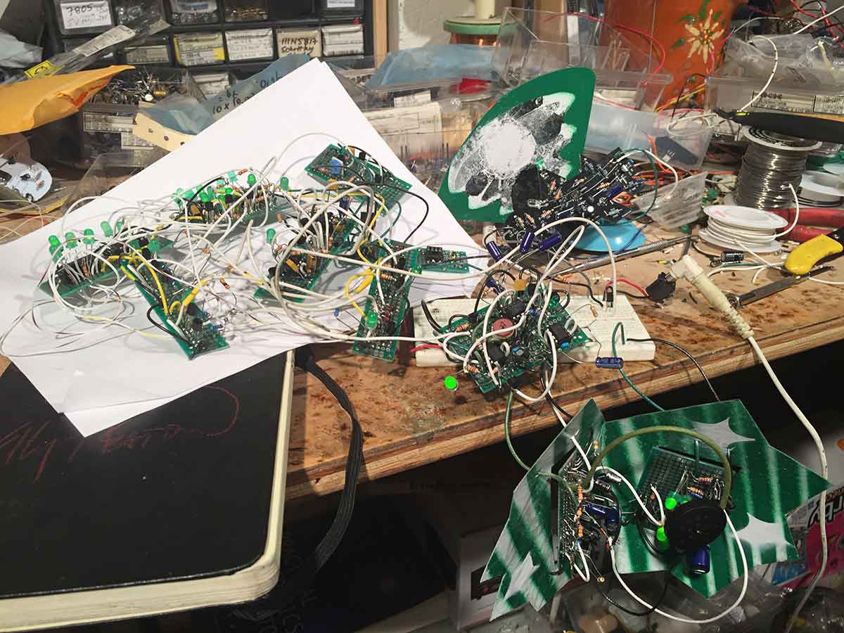
Mother Nature in perfboard (+more tips)
10/15/2018 at 22:49 • 0 commentsI've been busy migrating my "Mother Nature" controller circuit out of my breadboard and into perfboard... and yes, it's insane but no, I don't have time to produce a printed circuit board because I'm leaving in six days for a fellowship in Mexico. For the record, I do not recommend soldering so many components and connections in perfboard because the risk of error is high, either from bad solder joints, signal interference, or just plain confusion. I plan to design a printed circuit board for future embodiments of Mother Nature. Stay tuned.
As you can see in my previous log, I'm surrounding my perfboard circuits with spray painted cardboard to make them look cool -- and by the way, you could use this quick-and-dirty strategy to make a "starving artist's badge" for the Hackday Superconference.
![]()
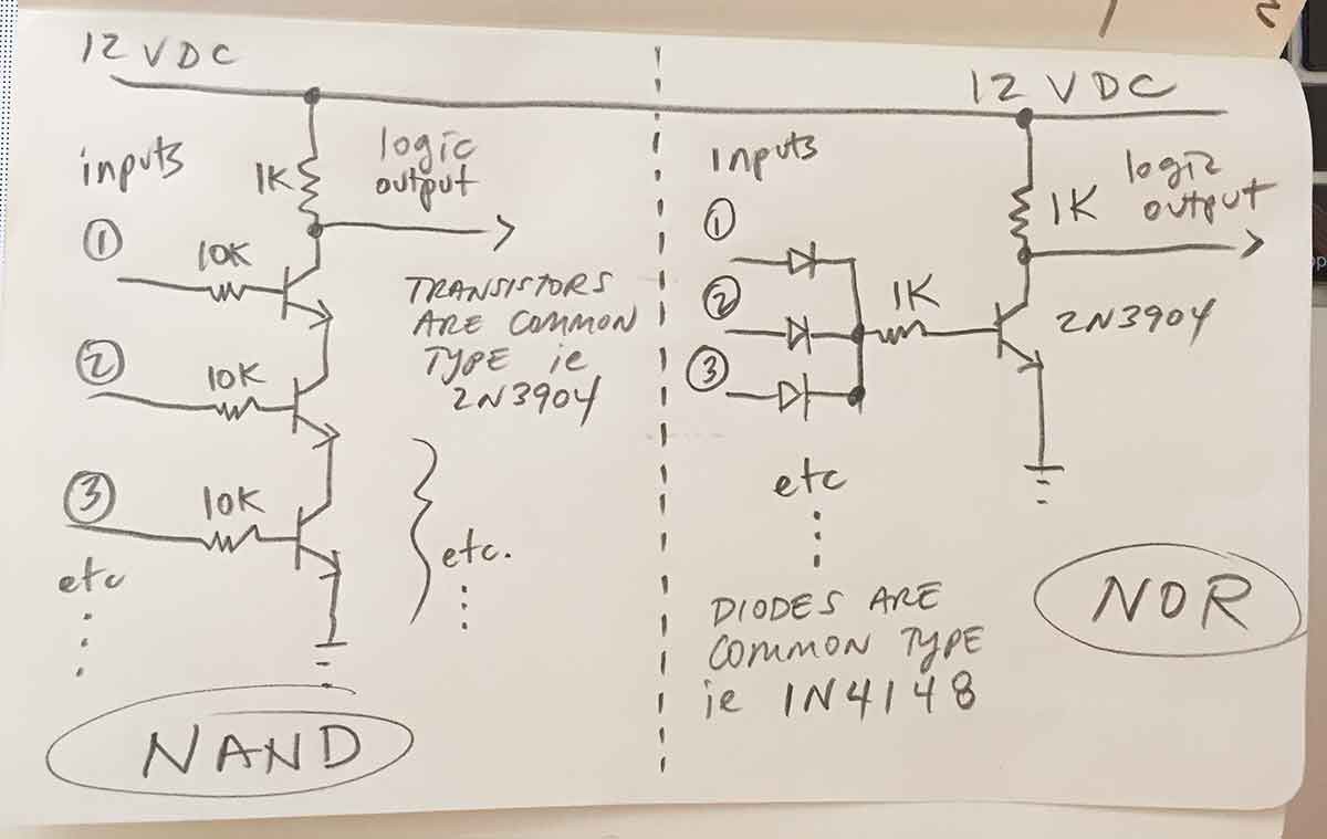
As for the design of my "Mother Nature Board," aka random pulse generator to trigger various events, I have some additional technical tips to share:
- Don't have logic ICs on hand? Build discrete transistor gates. This approach has the advantage of common components (NPN transistors, resistors, diodes) and you can add multiple inputs to the same gate -- which is useful if you discover that an event is triggering too often... just add another input to the gate and the outcome will become less frequent. Not triggering often enough? Remove or change an input to the gate. You can even tie an input to ground (or power) and let the other fluctuate. I use 2N3904 transistors for as many things as possible, but you could also build these cool light gates described by @Dr. Cockroach
![]()
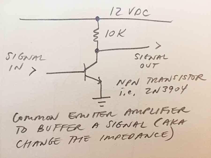
- There's a limit to how many things you can drive directly with a signal such as the output of a logic gate. Good engineers read data sheets and calculate voltages and current at various locations in their circuit. Impatient engineers add a generic common emitter amplifier between the signal OUT from a logic device and the signal IN to whatever you're driving. This hand-waving approach to buffering will not work in all cases! But it will probably work for most slow logic applications where you want to transform a signal multiple times and drive some light loads. I'm an artist who prefers prototyping to math, so I work a lot with "try it and see" circuit design. Plus, I am not building a nuclear reactor. Note that a common emitter amplifier will invert your signal. Pay attention to whether you need your signal to be active high or active low. Note that a 555 timer in monostable aka one-shot configuration is looking for an active low input. If necessary, invert the signal again to get what you need.
![]()
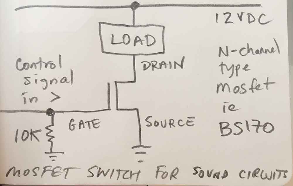
- Mosfets make great electrical "on/off" switches because they don't draw current on their gate (==the mosfet equivalent of a transistor's base). They just need a voltage. I use mosfets for the last step in my Mother Nature circuit, or the point at which I want to turn power on or off to a particular sound circuit (the load). Make sure you have a gate resistor to ground or voltage will "sit" on the gate even when the signal is low (and the mosfet won't turn off).
![]()
I hope these tips are helpful. To end this log, I give you a video showing my Mother Nature circuit in perfboard with two sound circuits hooked up. If you watch the LEDs carefully, you will see how certain combinations of logic are triggering the sound circuits. The cricket is wired up to chirp most of the time, whereas the Katydid is triggered less frequently. For this demo, I hooked up only two sound circuits because it's already hard to understand what is happening, and more circuits becomes a sort of natural chaos... which is my goal, as you will see in forthcoming logs.
-
Electrolier (September night in Virginia)
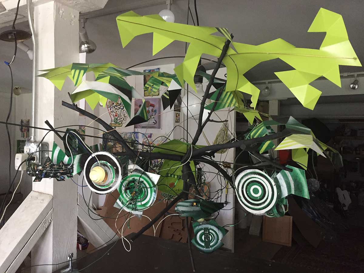
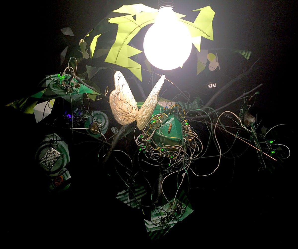
10/20/2018 at 18:30 • 4 commentsI've been working around the clock to finish my Hackaday Prize application and pack for Hacking Nature's Musicians in Mexico. As closure for my recent chapter, the various circuits that I've shown you over the past few weeks have migrated from my bench and into a sculpture titled "Electrolier (September night in Virginia)," 2018. Here is an informal video:
The video quality isn't great... (shot with my iPhone under bad lighting and extremely messy studio)... but hopefully you get the idea (see second video below). The sculpture contains one instance of my Mother Nature board design, recognizable by the dense tangle of white wires connecting logic gates, and six sound generating "animal circuits" each with its own speaker. The colorful graphics are spray painted cardboard, and everything is hung on a tree structure under a moon (globe pendant bulb). Oh, and that large moth is made out of silk velvet that I dyed and embroidered with an old industrial "Ultramatic" machine. I would have used small molex-style connectors to connect everything, but there was just no time.
![]()
It's interesting that so many long wires didn't screw up my signals. I credit this to my use of common emitter amplifiers to buffer the signals, and the fact that I'm not drawing much current for anything you see (or hear). The whole sculpture is powered with a 12VDC / 1.5 amp power supply. I also used multiple 0.1 uF ceramic capacitors between power and ground on most of the individual perfboards. It's critical to remember power-ground capacitors when you're dealing with a lot of amplified signals banging on your power rails. I'm careful to avoid really small gauge wire, and I add many pathways to ground ("let ground abound.")
![]()
![]()
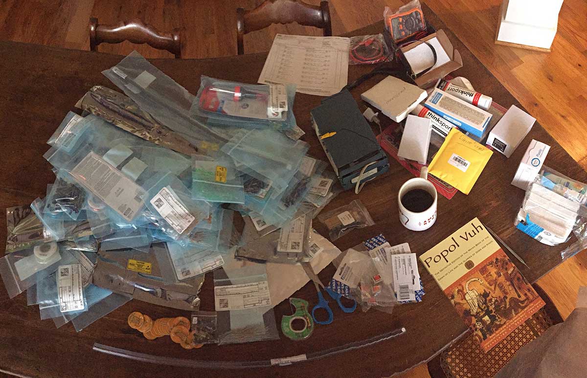
So... now I am packing my electronics bench into a suitcase and praying that security does not detain me at the airport. I'm throwing in packets of desiccant and crossing my fingers that jungle humidity doesn't zap everything. Making analog electronic circuits in the jungle will be interesting to say the least -- stay tuned for the sounds of los músicos de la naturaleza en Quintana Roo!
![]()
![]()
Hacking Nature’s Musicians
An artistic ecosystem of analog electronic sound generators