 Stephen Harrison
As you can see from the schematic below, IO7 isn't particularly complicated. 13 NeoPixel LEDs, 3 0603 LEDs for the colon and decimal place, a 3v3 regular and logic buffer to convert from ESP8266 3v3 logic to the 5V required by the LEDs. 3535 size LEDs were chosen rather than the regular 5050's that wouldn't fit within an inch.
Due to the density of the LEDs on the PCB as well as the pad placement, hand soldering really isn't a viable option, after ordering the PCBs from OSH Park I ordered a top stencil from OSH Stencils, with a swipe of solder paste the PCB is ready to fit the LEDs.
The back of the PCB is also tight but hand solder-able, so I didn't worry to try and reflow the back.
I used my ReflowR to reflow the PCB. The NeoPixels are very delicate for temperature and moisture, I baked mine at 70°C for a few hours before reflowing. It may be possible to reflow with a hot air gun but great care would need to be taken to not melt the LEDs!
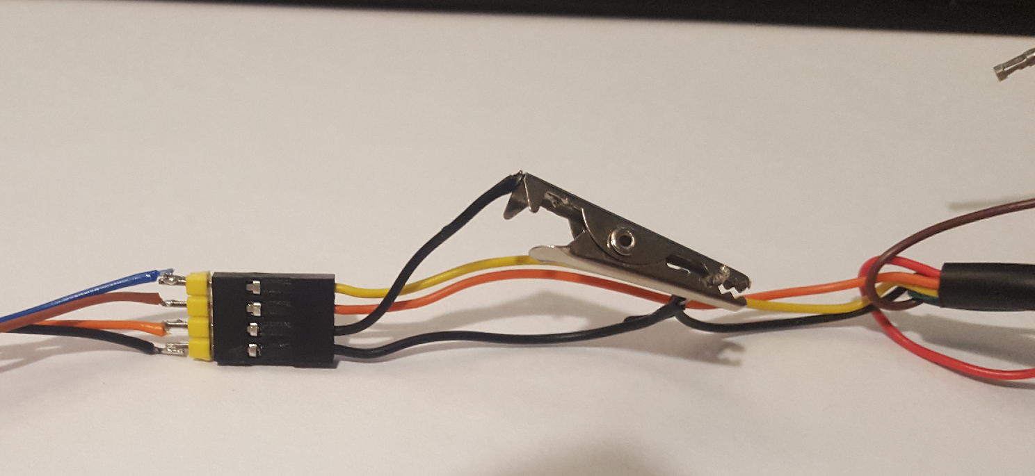
The PCB back is a little messy, I didn't have room for programming headers so I've tacked the wires directly onto the ESP12. This might be easier to program the ESP12 with Pogo pins before or after soldering and to use OTA firmware updates going forward, but for now, some tacked on wires and a 3v3 FTDI cable work well enough.
Blue: TX
Brown: RX
Orange: D0
Black: GND
Additionally Red+Black provide 5V to the on-board 3v3 regulator.
I hacked a FTDI to connect to the ESP programming wired, D0 ended up connected to a croc -lip rather then being pulled to ground through the connector to make it easier to take the ESP out of reprogramming mode.
I pushed some basic code to the ESP to light the LEDs, using the Adafruit Arduino Neopixel library fully expecting to have one or more blown LEDs through the reflow process. To my amazement all the LEDs worked straight away.
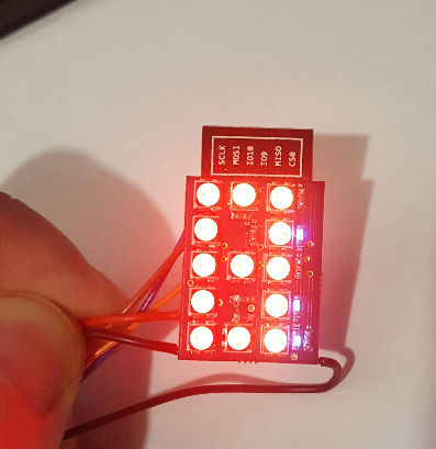
It's nice when something works first time :-)
Discussions
Become a Hackaday.io Member
Create an account to leave a comment. Already have an account? Log In.