 Dr. Cockroach
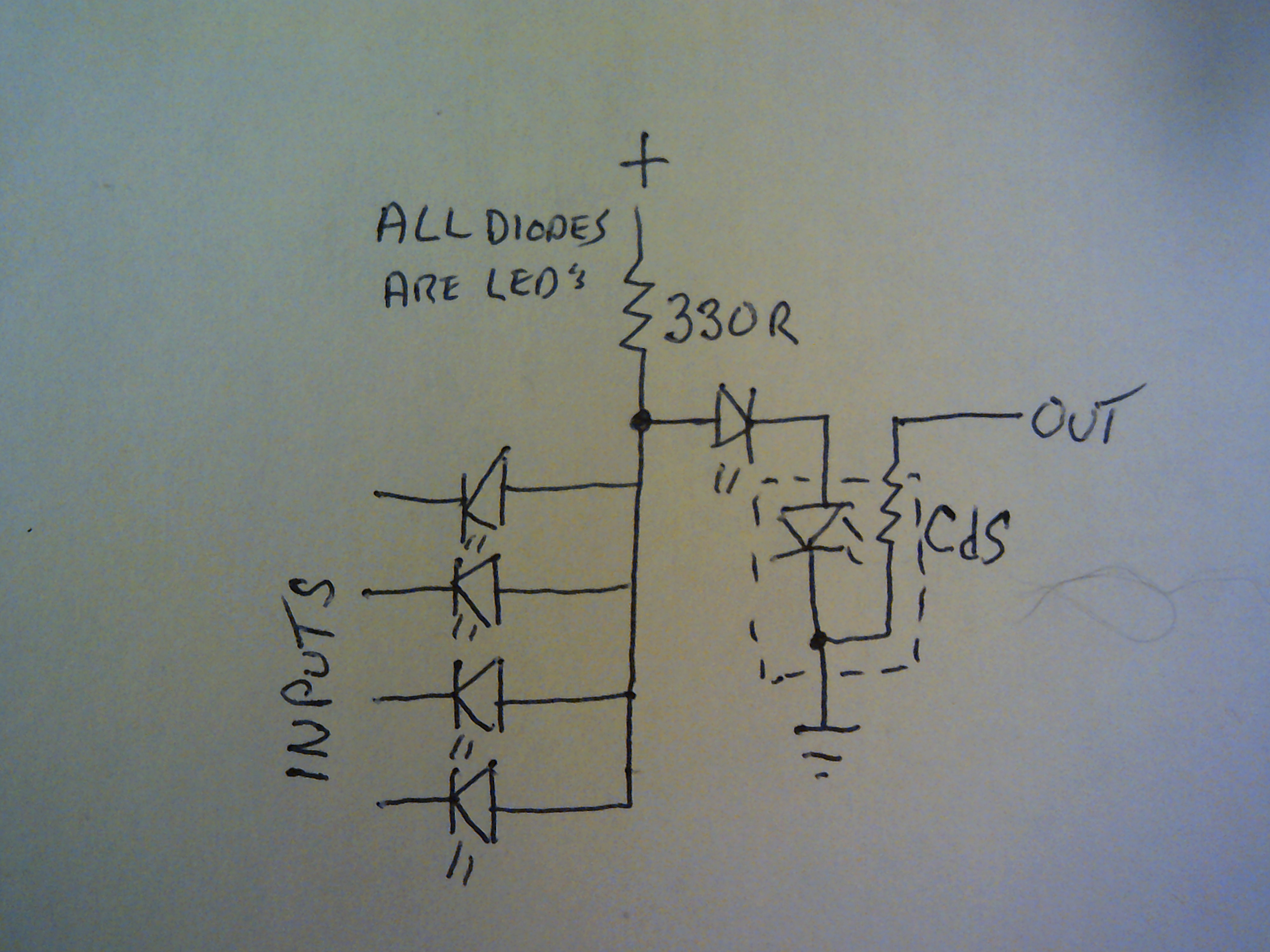
April 6, 2021 - Working with a free form idea of replacing input switching diodes with Leds. This is a 4 input NAND gate that shows the logic flow from input to output. This circuit works well with my existing Light Logic gates.

Input diodes are either to ground through a prior CdS LDR for a zero or open for a one. Minimal stress on the input Leds as the CdS minimum resistance is at a safe level of about 300R or higher.
Discussions
Become a Hackaday.io Member
Create an account to leave a comment. Already have an account? Log In.
Very lovely!
One thing that worries me a little is that, I think, LEDs aren't particularly good at being blocking diodes.
For low voltages that should be perfectly fine, but as voltages go higher I think they might get unhappy being run in reverse, so I'd just double-check with the datasheet what they're rated for and/or perform some destructive stress testing to see the limit of them ^^
Are you sure? yes | no
Ahh, but the Leds never run in reverse..... The input diodes either are grounded by the prior CdS stage or essentially open. Grounded is a zero and open/no voltage is a one. There is no actual logic level other than zero being low resistance to ground :-)
Are you sure? yes | no