 Ken Yap
Another clock?
There is nothing particularly special about this clock, except perhaps that is is built from a 8042 microcontroller chip (henceforth MCU) salvaged from a very old PC. The most modern component is the integrated serial display which keeps the component count down.
Why did I embark on this project when I could have written this for a modern PIC or AVR MCU, which would be cheap enough and consume less power?
- I wanted to get back into the game and get up to speed with advances in MCU technology since I started decades ago. See my discourse in the next section.
- I have lots of chips of this era, pulled off PC motherboards. So I can take chances with them and not feel sad destroying something I bought.
- I wanted to do something substantial with these chips. There are a few pages on the Internet, for example DevSter and this video where people have got this MCU to work, and then were satisfied after getting LEDs to flash. The most complex one I saw ran a scrolling display.
- I wanted to push the envelope of these old chips and show that even with old technology you can achieve a low component count by design.
- I wanted to do something not run-of-the-mill. Anybody can wire up an Arduino to a serial display and write clock firmware in C. For this I needed to get low down with assembler and I already had most of the code from a previous project.
I believe constraints are good for learning to problem solve; they make you flex your mental muscles more.
Note that although I have designed a clock, the circuit can in fact be used for other purposes, it's all shaped by the firmware. You could make a metronome, a period timer or something else.
I will be putting logs of milestones in the log section and this details section will describe the results. So I may update the particulars if they change.
An entire section that used to be here has been moved to its own log to allow the narrative to flow better.
The 8042 family
The most widespread use of the 8042 chips was the keyboard controller in PCs, but only up to a certain time. After that the controller functions were taken over the 8051 family (possibly the most durable family of MCUs) or integrated in super BIOS chips. So to scavenge these chips look for very old PCs, say 486 and earlier.
The 8042 family of chips is similar to the 8048 family and has the same architecture inside, but was designed to be peripherals. There is also an External Access (EA) pin which is what allows us to put programs in external EPROM. The main differences are:
- Some instructions are deleted and some added. However these changes are generally not instructions you need. If you avoid those instructions, an 8048 assembler will work. Some like the ASXXXX series can be set to 8042 mode which catches any use of unavailable instructions.
- You cannot add external RAM if you need more than the 64 or 128 bytes internal RAM.
- In EA mode instead of multiplexing the data bus and the low byte of the address bus on the data lines, the low byte of the address is output on port 1. This means that you don't need an 8-bit latch to demux the data and address saving one interface chip. On the other hand, you lose direct access to port 1 and need a (different) 8-bit latch if you want to use this port. The bottom 3 bits of port 2 are always multiplexed and you would need a latch anyway if you wanted to use them. The top 5 bits are available as I/O pins as before.
- The T0 and T1 input pins are available too, but the I pin isn't. It is possible to trigger an interrupt by other more complicated means, but there isn't a testable I bit without using interrupts.
Now the members:
- 8041: 1kB mask ROM, 64B RAM, up to 6 MHz clock
- 8042: 2kB mask ROM, 128B RAM, up to 12.5 MHz clock
- 8741: EPROM version of 8041
- 8742: EPROM version of 8042
- 8242: An 8042 but with one of several off-the-shelf keyboard controller firmwares inside
I have not seen an 8241, presumably the keyboard firmware authors had no need to use...
Read more »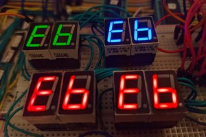
 John Lonergan
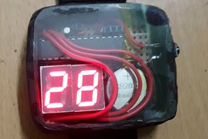
 Brainy.Baboon
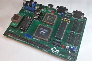
 Colin Maykish
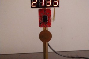
 Pierre-Loup M.