Main PCB
The PCB is designed around ATMEGA328P processor, running on 8MHz (internal or external resonator), which makes it Arduino Pro Mini compatible. The ISP and serial pins are exposed on a 1.27mm pitch header for easy programming. Charging is done via a micro USB and a linear 1s lithium charger (TP4056). Even though the software makes sure that the battery doesn't discharge too much, there's also a lithium protection IC on the PCB for redundancy. One the front side, there's a tactile button and a RGB led, as well as connectors for battery, heater and optional external button. The circuit is designed to be a drop-in replacement for my previous version of the heating system that worked with commercial Therm-ic insoles with 10ohm heaters, so there is a boost converter onboard. However, the new custom PCB heaters are designed to work directly with 1s voltage for improved efficiency.
Heater PCB
Placed under the insoles (front par, under toes), this PCB must be made as thin as possible. I used the thinnest possible option at JLCPCB, which is 0.6mm. My heaters came out at around 4.2ohm, which is close enough to work as intended.
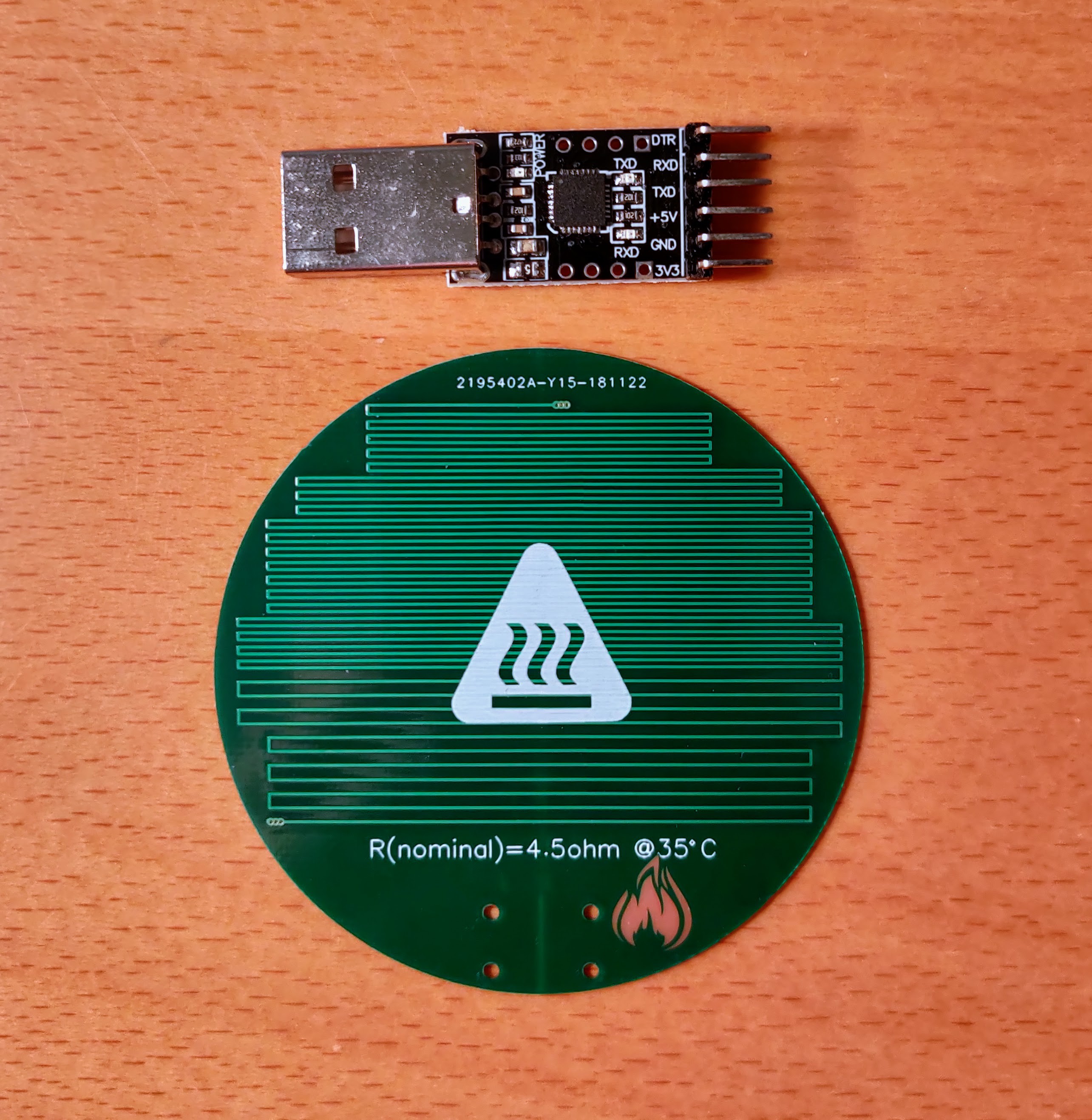
Cheap USB to serial adapter for scale
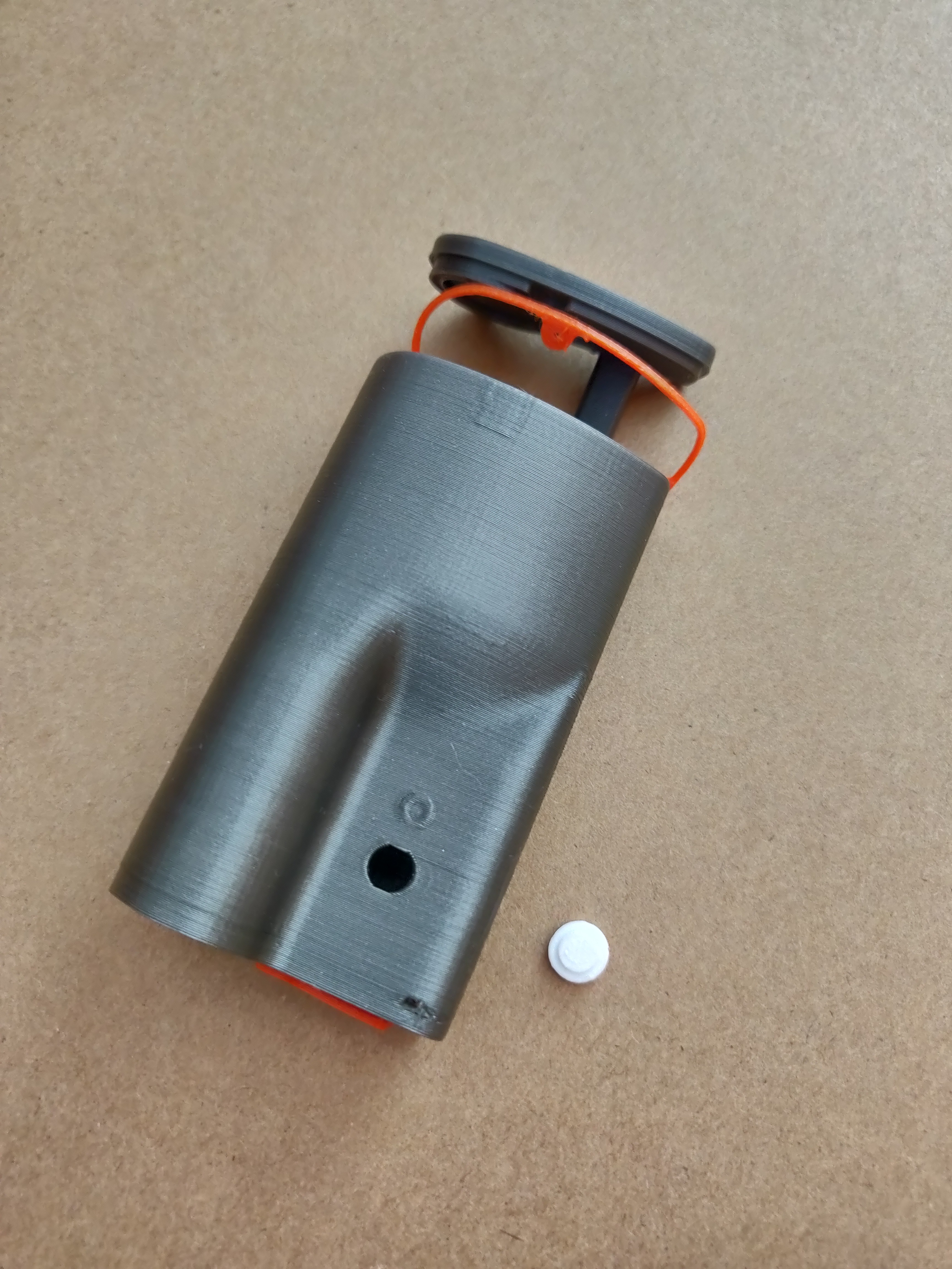
Case
The case for the battery and main PCB is 3D printed. It's designed to be as small as possible, so it's not bulky when attached to the back of a ski boot. The walls of the case are thin, so the button can be pressed by pressing directly on the case, just above the LED. USB hole and top lid are sealed with parts printed from flexible material. I glued the heater cable directly into the lid, which is not perfect. Still looking for a watertight connector for a flat cable. The case is attached to a ski boot with velcro for easy removal if needed.

 bobricius
 makeTVee
 Jelto
Jelto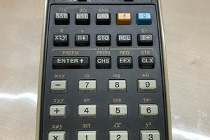
 CYUL
CYUL
I really like this! When I used to ski I always had boot problems - the tongue of my boot would pinch the top of my foot and reduce the blood flow enough that I'd get frostnip very quickly. Ruined more than a few runs that way. This looks like it would help.