 Stefan-Xp
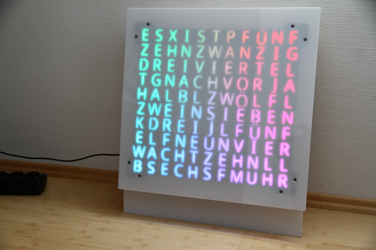
The mAtriX effect - But in person it looks nicer ;-)
0%
0%
JAWC - Just another Wordclock
Just another Wordclock with Arduino and WS2812B
Become a Hackaday.io member
Already have an account? Log in.
Just one more thing
To make the experience fit your profile, pick a username and tell us what interests you.
Pick an awesome username
hackaday.io/
Your profile's URL: hackaday.io/username. Max 25 alphanumeric characters.
Pick a few interests
Projects that share your interests
People that share your interests

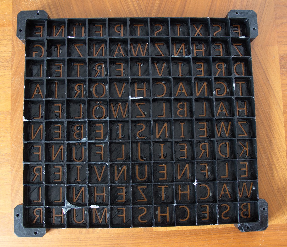 As you can See the Backside has some issues ... blobs of XTC 3D and some pieces of the underlaying Material. Nothing to bad - since not visible.

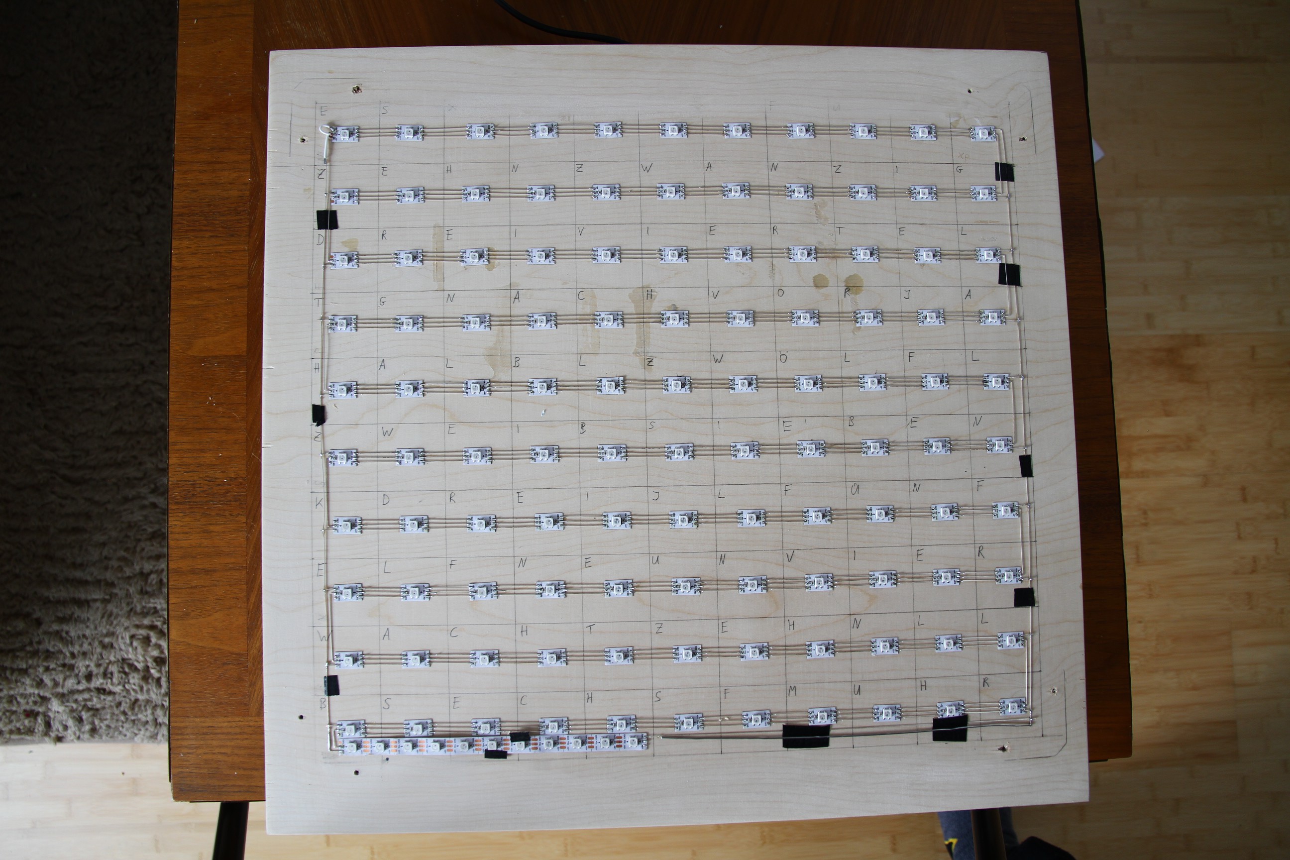
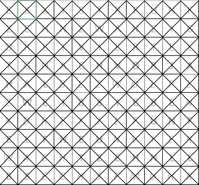 This template is going to be transfered to the Wooden Sheet.


 Andrew Cooney
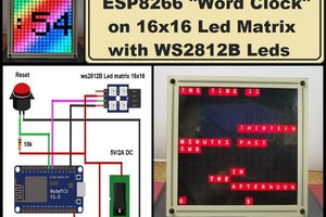
 mircemk
 Robert Gill
 Marius Taciuc
Great design!