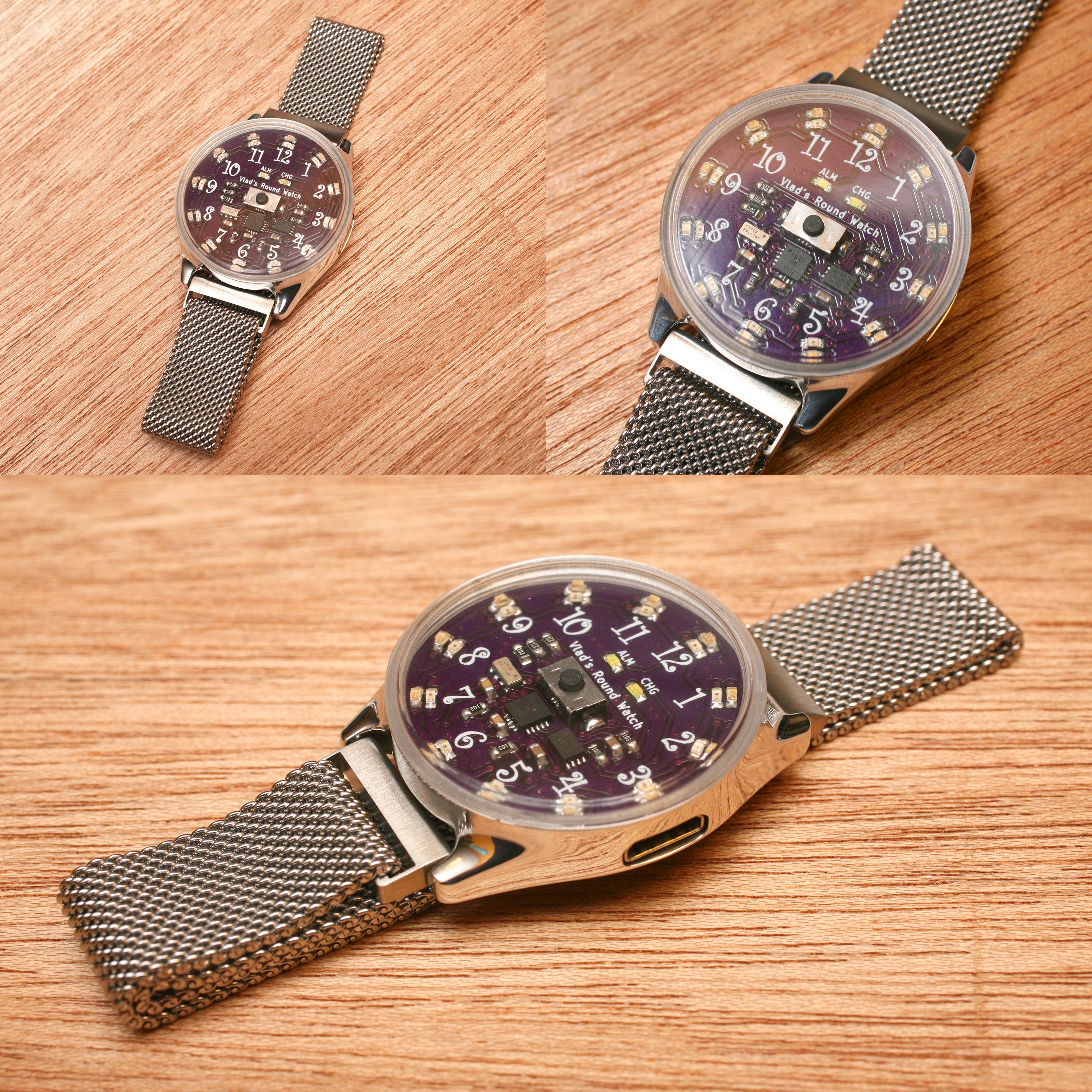
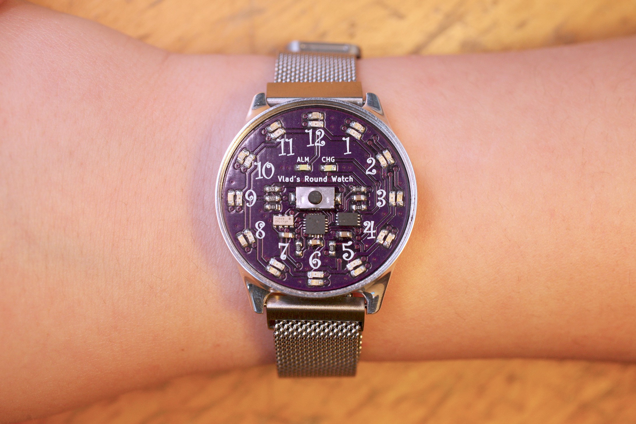
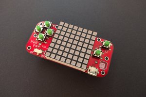
I settled on a Tiny841 because it had enough IO's for what I wanted to do, and because it was supported by the Micronucleus bootloader, so I could program it over USB. For driving the LEDs, I found the IS31FL3235 from ISSI, which is a 28 channel LED driver and communicates over I2C. For timing, I choose the LCC8 M41T62 from ST because it had an integrated crystal in an incredibly small package. Lastly, an MCP73831 from Microchip handles the lipo charging.
I've been working on it in my spare time over the past 2 to 3 months and it's coming down the home stretch. Here's a video of the basic functionality:
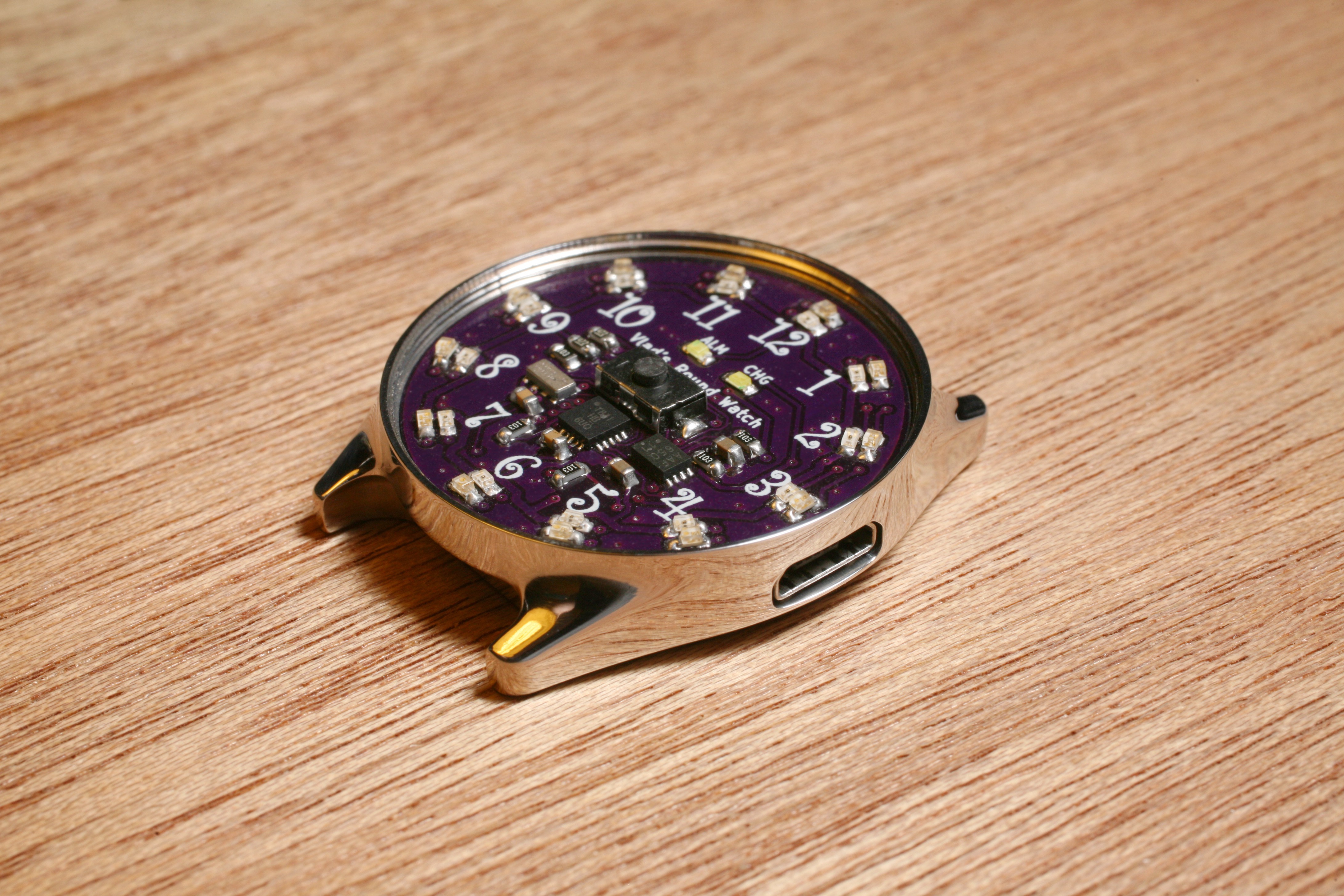
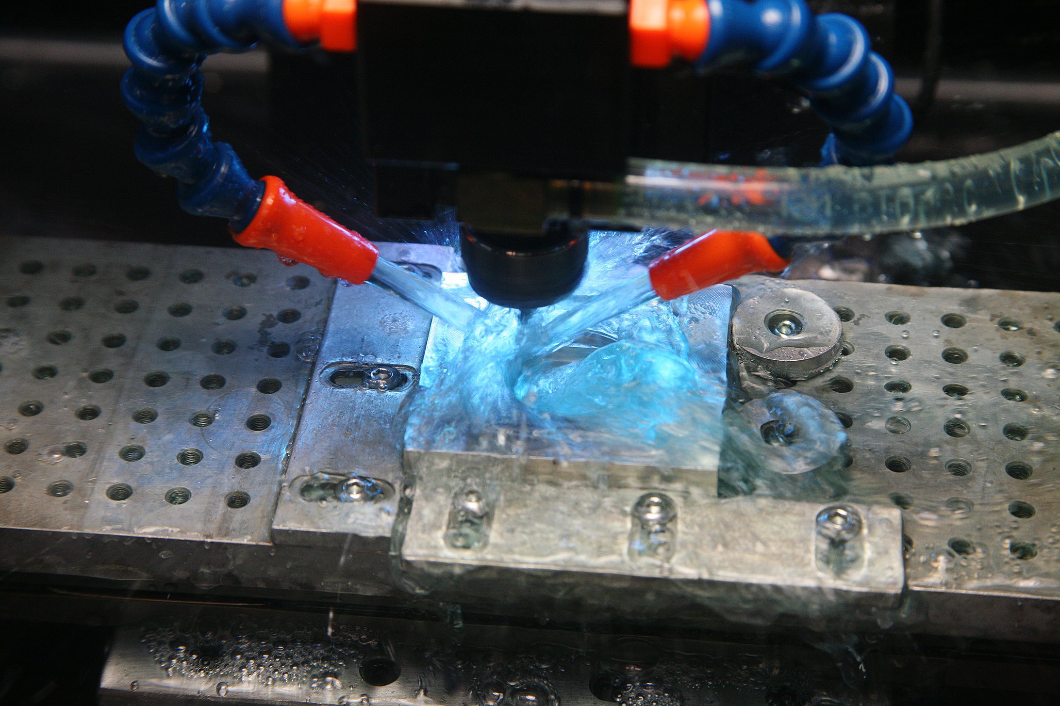
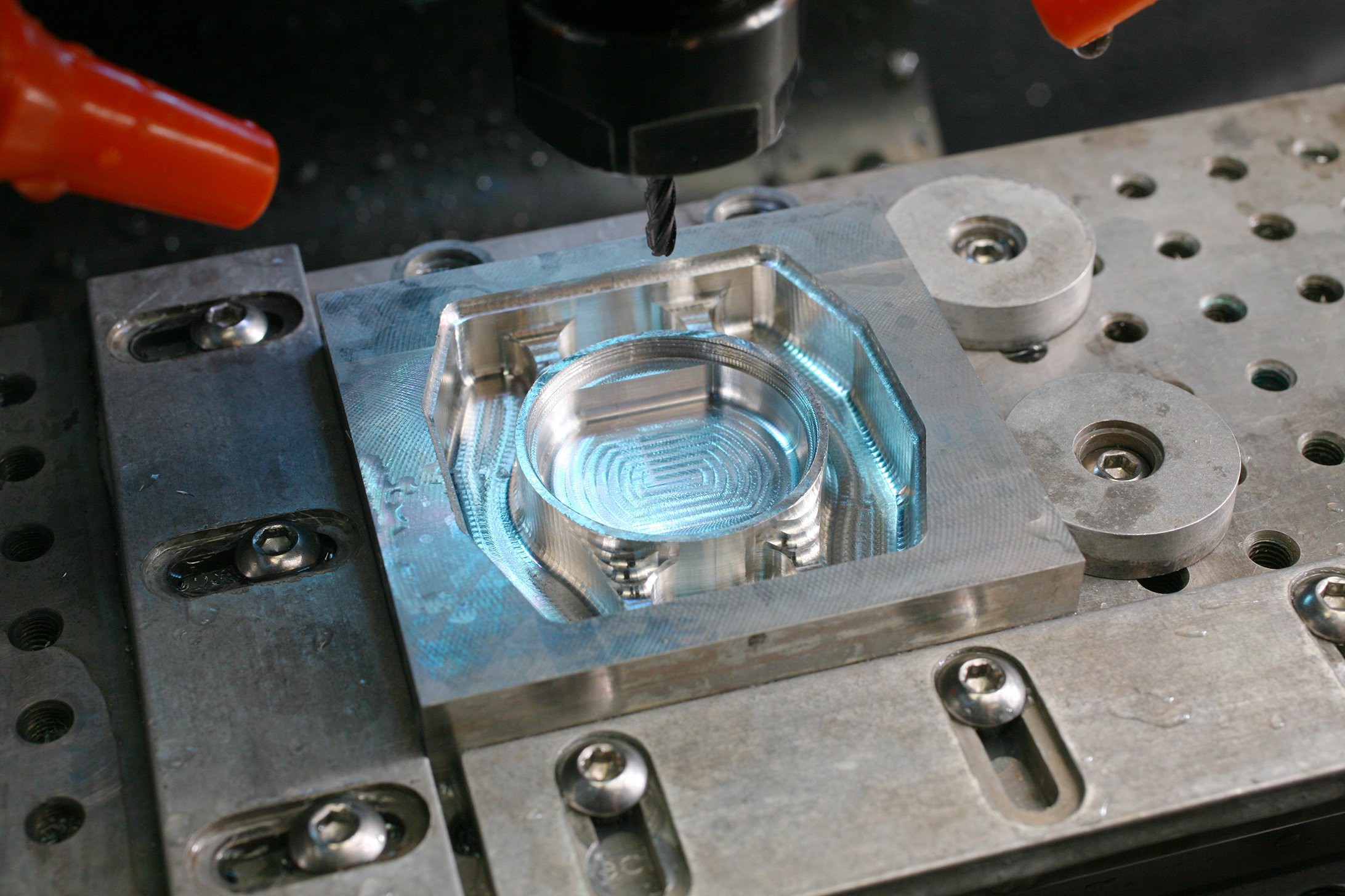
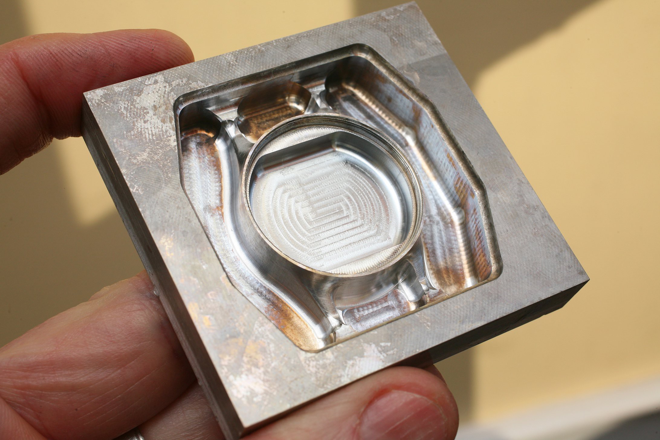
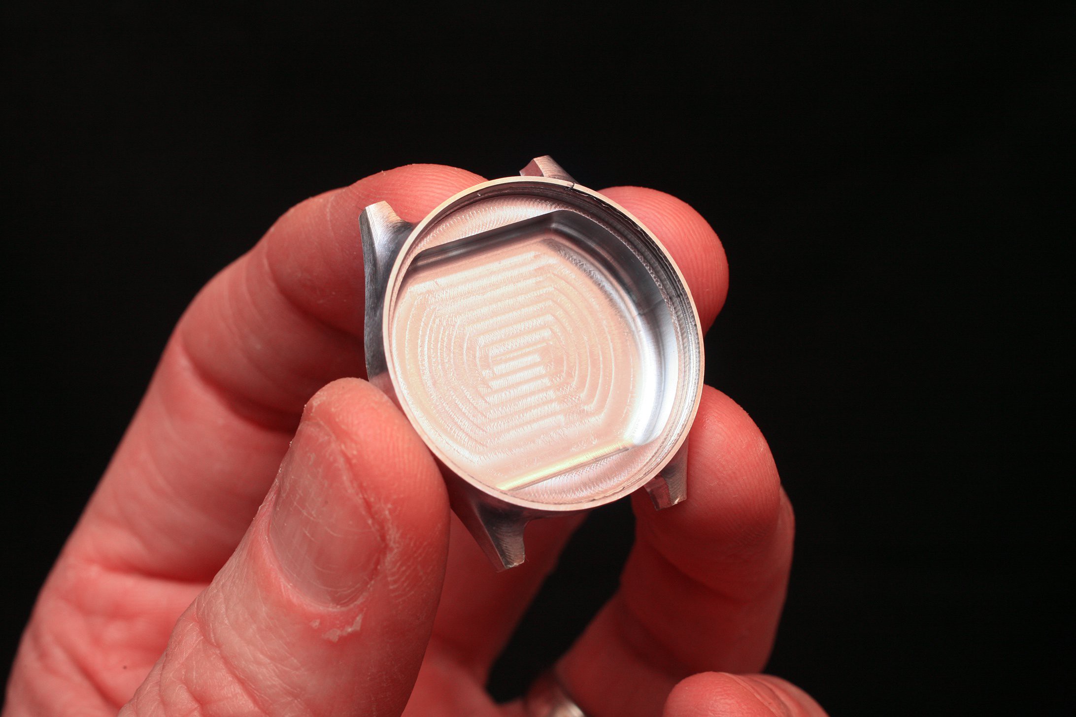
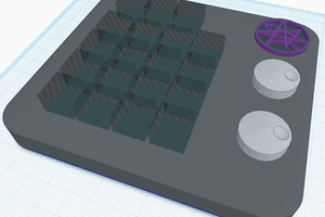
I've started working on the case/housing for it. I just made a test case from clear acrylic on a Taig CNC mill before making the final piece from aluminum. The face will be clear acrylic or polycarbonate, whichever I have on hand. The face piece will screw into the aluminum housing, hold the PCB in place, and the face itself will be thin enough to be mildly flexible, so he'll be able to press the button "through" the face.


 deʃhipu
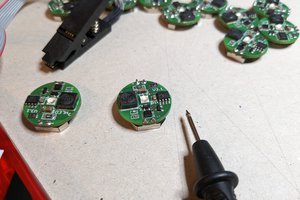
 schlion
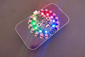
 mrpendent
Hi, thanks for this great project
please is the source code available for learning purposes?